
Effect of Working Temperature on the Resistance Characteristic of aPleated Stainless Steel Woven Filter*
2009-05-15 01:40LIJuan李娟SHIYumei石玉美andWANGRongshun汪荣顺
关键词:李娟
LI Juan (李娟)**, SHI Yumei (石玉美) and WANG Rongshun (汪荣顺)
Effect of Working Temperature on the Resistance Characteristic of aPleated Stainless Steel Woven Filter*
LI Juan (李娟)**, SHI Yumei (石玉美) and WANG Rongshun (汪荣顺)
Institute of Refrigeration and Cryogenics, Shanghai Jiao Tong University, Shanghai 200240, China
Effect of working temperature on the resistance characteristic including the permeability coefficient and the pressure drop evolution of a pleated stainless steel woven filter with a nominal pore size of 0.5 μm has been studied. The permeability coefficient was obtained based on the pressure drop data and the Darcy’s law. In three filtration experiments, pure carbon dioxide at 283 K, nitrogen at 85 K and liquid helium at 18 K are adopted, respectively. It is found that the permeability coefficient decreases at the working temperature due to the cold shrink of the filter element at cryogenic temperature. Then, two kinds of feed slurries, mixture of liquid nitrogen and solid carbon dioxide at 85 K, and mixture of liquid helium and solid nitrogen at 18 K, flow into the filter cell. The solid particles are deposited on the filter surface to form a filter cake and the purified liquid flows through the filter. It is found that the pressure drop evolution shows the same trend on these two temperatures, which can be divided into three stages with high filtration efficiency, indicating the feasibility of the filter for cryogenic application. However, variant cake resistances are obtained, which is resulted from the different interactions between solid particles in the feed slurry at lower working temperature.
resistance characteristic, permeability coefficient, pressure drop, woven filter, working temperature
1 INTRODUCTION
Pleated stainless steel woven filter with fine pore size of several microns is one of the most preferred, effective and economic media for solid-liquid separation. Pleated structure, compared with normal flat configuration, is beneficial to moderate the increasing ratio of pressure drop due to its larger filtration area [1]. Stainless steel owns favorable ductility so that it does not easily fracture under mechanical and thermal shocks [2]. Woven medium, known as “surface” and “cleanable”, owns moderate porosity, permeability, pressure drop and separation efficiency in comparison to fleece and granular ones [3].
As a result of the advantages above, the pleated stainless steel woven filter medium can be reused many times with consistent filtration performance. Compared with sintered glass frit, compacted means of iron oxide particles, nylon mesh and sintered ceramic [4-7] used for filtration procedures at cryogenic temperature, stainless steel is a much more excellent material due to its favorable resistance to prevent brittle fracture. Many studies have been dedicated to the mechanisms and applications of this filter medium in industrial processes at room and especially high temperature [8-10], but virtually few literatures are available concerning their behaviors at low temperature [11].
The filtration process of the pleated stainless steel woven filter medium belongs to the cake filtration. Cake filtration is frequently used for the removal of particulate solids from fluids in industrial processes. The build-up of a filter cake is usually accompanied by an increased pressure drop over the filter medium [12]. Permeability is characterized by the filtration coefficient, which is an inherent property of the filter medium, and mainly depends on the physical structure of the filter such as porosity, pore size and pore numbers per filtration area [13]. However, some external factors including working temperature may have some impact on the coefficient [14].
In this paper, a series of experiments are conducted to investigate the effect of working temperature on the permeability coefficient and pressure drop evolution of a pleated stainless steel woven filter with an emphasis on the conditions at cryogenic temperatures.
2 EXPERIMENTAL
The experimental setup (Fig. 1) is composed of the following six parts: (1) liquid delivery system; (2) gas filling system; (3) a mixing chamber, in which gas is solidified into solid particles at the liquid temperature, and mixes with the liquid thoroughly and uniformly to form the feed slurry; (4) filter cell including the filter element and a housing; (5) cryogenic vacuum system and safety system including a vacuum gauge, a burst disc and a safety valve, which can monitor the vacuum state in the interlayer of the experimental dewar, decrease the evaporation of cryogenic liquid and guarantee the safety of the system; (6) measuring system including two gas flow rate gauges (type of M-100SLPM-D/ 5M, accuracy of 1%), two pressure gauges (type of MPM4730, accuracy of 0.1%), a temperature device (type of AMAC silicon diode, accuracy of 0.003%) to monitor the fluid state, and a gas concentration detector (type of F2000-CO2, accuracy of 2%).

Figure 1 Schematic depicting the experimental setup
Figure 2 Structural sketch of the pleated 316 L woven filter (Unit: mm)
1—cap; 2—boss; 3—perforated tube; 4—filter element

Table 1 Specifications of the pleated stainless steelwoven filter
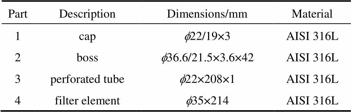
Table 2 Four parts of the pleated stainless steel woven filter
Pressures, temperature and gas concentration are regulated, monitored and recorded continuously throughout the experiments. Since the flow rate gauges can only be used at temperature of the entering fluid higher than 10°C, an air heat exchanger is adopted to vaporize the filtered liquid medium. What needs to be explained is that, for pure cryogenic liquid, the readings of the flow rate gauge in the outlet is exactly the gas state flow rate of the liquid, and can be transformed to be the liquid flow rate based on the density of the two phases. However, as for the purification experiments, since the volume ratio of the filling gas and the liquid is very small, and the filter is tested to be a high efficient one, then the readings of the outlet flow rate gauge are deemed as that of the filling liquid, and the resulted error can be ignored. The particle size of CO2and N2solids are assumed approximately to be in the range of 0.05-2 mm based on the related theoretical and computational study [15-18].
The filter is a pleated stainless steel woven medium with an outer diameter of 35 mm and a length of 214 mm, and is made up of two layers of mesh sintered together to form an integrated porous element. The mesh is of very fine gauge and determines the filtration efficiency. It is overlaid with a coarse support mesh layer with bigger pore diameter of 3 mm. The structure sketch of the filter is shown in Fig. 2. Specification and four parts of the filter are summarized in Tables 1 and 2, respectively.
Two groups of experiments are carried out:
(1) Three kinds of pure fluids including carbon dioxide at 283 K, nitrogen at 85 K and helium at 18 K, flow through the filter, to measure the permeability coefficient of the filter and examine the influence of working temperature.
As shown in Fig. 1, pressure gauges are located at the flowing pipelines, not exactly at the inlet and outlet of the filter cell. Therefore, Bernoulli equation is adopted to calculate the exact pressure drop generated by the filter [19]:

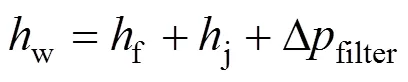
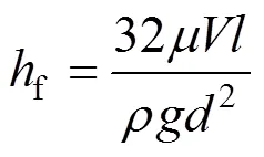
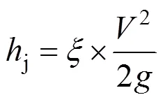
whereis the horizontal height,is the absolute pressure,is the gravity of unit fluid mass,is the fluid velocity,is the gravity acceleration,wis the total resistance loss,fis the on-way resistance,jis the local resistance, Δfilteris the pressure loss generated by the filter core,is the fluid viscosity,is the path length,is the fluid density,is the pipe inner diameter, andis the local resistance coefficient.
Permeability coefficient is calculated base on the Darcy’s law, which is applied for laminar flow:
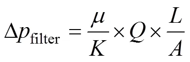
whereis the permeability coefficient,is the fluid volume flow,is the filtration depth,is the filtration area.
(2) Two kinds of feed slurries, mixture of nitrogen and carbon dioxide at 85 K, and mixture of helium and nitrogen at 18 K, flow into the filter cell, respectively. Flow rate of two cryogenic liquids and volume ratio of solids are maintained constant in these two mixtures. During filtration, solids are deposited on the filter surface and pure filtrate flows downstream. Pressure drop evolutions are monitored and recorded, and the filtration efficiencies are calculated as follows:
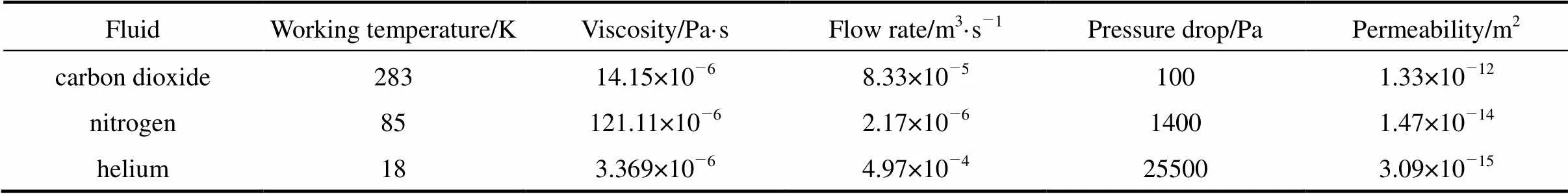
Table 3 Three experimental conditions

whereis the filtration efficiency,downandupare the volume ratios of solid in the filtrate and in the feed slurry, respectively.
3 RESULTS AND DISCUSSION
3.1 First group experiments: permeability coefficient measurement
Table 3 shows three different conditions including the working temperature and corresponding fluid viscosity, flow rate, pressure drop, and the calculated permeability coefficients based on Eqs. (1)-(5).
It is found that, in general, the permeability coefficient decreases with the working temperature. The relation between permeability and working temperature is not linear, and the permeability at room temperature is two to three orders of magnitude higher than that at cryogenic conditions. This can be explained by the cold shrink [20] of the woven filter element at low temperature, which changes the flow path structure and results in the reduction of the porosity and the permeability. This result is coincident with that in the literature [8], in which it was indicated that the woven metal bag showed a distinct dependence of temperature, and filtration at elevated temperature caused penetration of a certain amount of dust into the filter depth due to the thermal expansion of the filter medium.

3.2 Second group experiments: purification of cryogenic liquids
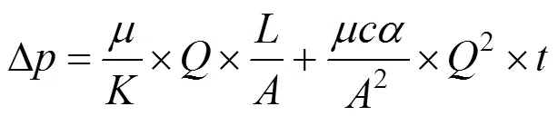
The purification is conducted under a constant fluid velocity,.., the flow rates of filling gas and liquid are maintained stable during a filtration process. Theoretically, the total pressure drop Δmcomprises two parts as expressed in Eq. (7) [21]. Δmis resulted from the filter medium, which can be calculated by the Darcy’s law (5) [22] and is affected by the permeability constant. Δcis generated by the evenly thickened filter cake, which is expressed in Eq. (8). As for constant-velocity filtration with an incompressiblefilter cake, the pressure drop will increase due to the second part which will increase the total resistance.
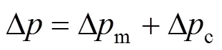
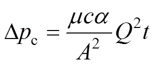
whereis the solid mass in unit cake volume, kg·m3;is the specific cake resistance, m·kg-1;is the fluid flow, m3·s-1;is the filtration time, s. Therefore, the total pressure drop can be expressed as follows:
3.2.1
Figures 3 and 4 depict data for the pressure drop and filtration efficiency as a function of filtration time under the nitrogen flow rate of 20 L·min-1(reading of the gas flow rate gauge in the outlet of the system) and the carbon dioxide flow rate of 2 L·min-1, respectively. The temperature is maintained at 85 K.

Figure 3 Pressure drop evolution
Figure 4 Filtration efficiency curve
It is observed in Fig. 3 that the pressure drop increases over time, which is consistent with classic filtration theories. Moreover, three different stages can be clearly identified:
(1) During the first stage, the pressure drop increases very slowly and can even be deemed as stable. Solid particles are mostly collected on the exterior of the woven filter and a small amount may deposit in the bottom space of the filter housing. No complete filter cake is formed. In this case, the pressure drop is only mainly generated by the filter element and is affected by the permeability constant. This stage lasts about 35 min.
(2) Pressure drop shows a sharp rise at about 40 min, and then the intermediate stage begins. In this stage, the plot appears a linear and stable increasing trend, which is the significant characteristic of surface filtration as shown in Eq. (9). As for the first item in Eq. (9), the pressure drop generated by the filter remains unchanged under a stable flow rate. However, as for the second item, the pressure drop resulted from the filter cake will increase over time due to the cake growth. Therefore, the complete filter cake is formed at the sharp rise point of about 40 min, which results in a break on the plot. This stage lasts about 120 min.
Comparing the first and second stage, another important conclusion can be brought out that the pressure drop generated by cake is much higher than that by the filter itself. This means that for this kind of pleated stainless steel woven filter, it takes the main function of filtration and the filter medium only plays a role of supporting after a completed cake is formed. This is another characteristic of surface filtration.
(3) A second sharp increase of pressure drop is observed in the beginning of the third stage. This can probably be attributed to the high pressure difference exerted on the filter cake, which leads the cake to be a little compressible to some extent and ultimately raises the specific cake resistance. This stage only lasts less than 10 min until the pressure drop reaches its maximum allowable value of 100 kPa.
These three stages are different from that in the depth filtration, as depicted in the Ref. [12], in which the filtration procedure is divided into 5 stages for solid and liquid aerosol mixture. Firstly, the pressure drop increases slowly due to that the particles are deposited preferentially on those already presented on the fibres to form aggregates. Then, the pressure drop rises sharply, which is resulted from the liquid bridges and films developed at the fibre intersections. The third stage is characterized by the formation of a filter cake. Then, a sharp increase is observed due to the higher energy needed for the liquid to percolate through the cake and the filter. The last stage is the drainage. These differences are resulted from the diverse structure of the filter medium.
Filtration efficiency is calculated according to Eq. (6). It can be observed in Fig. 4 that the efficiency in the whole purification procedure is higher than 90%, indicating that this pleated stainless steel woven filter is a kind of high efficient medium for cryogenic application. However, efficiency during the first stage is lower compared with that in the second and third stages, which further approves that the complete cake takes the function of purification and seems to be more efficient.
3.2.2
During this whole purification process, the temperature is controlled at about 18 K. To maintain this low temperature, helium flow rate (reading of the gas flow rate gauge in the outlet of the system) should be kept higher than 100 L·min-1. Figs. 5 and 6 depict data for the pressure drop and filtration efficiency as a function of filtration time under the helium flow rate of 100 L·min-1and the nitrogen gas flow rate of 10 L·min-1, respectively.

Figure 5 Pressure drop evolution
Figure 6 Filtration efficiency curve
It is observed in Figs. 5 and 6 that the plots of pressure drop and filtration efficiency appear the same trends with those in Figs. 3 and 4, and there are also three stages. These results indicate that the over-all pleated woven structure of the filter element remains unchanged upon the cryogenic temperature of 18 K and approves to be a favorable medium for cryogenic application.
The filtration procedure lasts a much shorter time, about 55 min, and the total pressure drop increases more rapidly compared with the last liquid nitrogen and carbon dioxide solids filtration. There are mainly two reasons. One is that the liquid flow rate and solid mass are 10 times higher, which induces a higher pressure drop generated by the filter element and a fast growth velocity of the filter cake. The other is that the interactions between solid particles may be different to some degree at a much lower temperature, which results in a variant property of filter cake, and ultimately affects the pressure drop and filtration efficiency.
4 CONCLUSIONS
Filtration tests are conducted with a pleated stainless steel woven filter to research its permeability constant and pressure drop evolution at different working temperature. The filter is approved to be a preferred medium for cryogenic application with the filtration efficiency of higher than 90%.
Permeability constants are measured based on the pressure drop data and the Darcy’s law at 283 K, 85 K and 18 K. It is found that the permeability constants decrease with temperature due to the cold shrink of the woven filter at low temperature, which changes the flow path structure and results in the reduction of porosity.
Purification procedures are executed at 85 K and 18 K. Three different stages could be identified for these two procedures and the pressure drop generated by filter cake is much higher than that by the filter element itself, which are the two significant characteristics of surface filtration. Pressure drop evolutions appear the same trends on these two temperatures, indicating that the over-all woven structure of the filter remains unchanged. However, the interactions between solid particles may appear different to some degree, which can result in a variant cake property, and ultimately affect the filter performance. This needs serious attention and further investigation.
1 Ning, Z., Zi, X.Y., Zhang C.R., Liu, J.H., Kuang, C.J., “Preliminary study on the characteristics of metal mesh filter and the reverse cleansing technology”,...., 39, 123-127 (2003)
2 Wang, R.Z., Wang, R.S., Cryogenic Engineering, Shanghai Jiao Tong University Press, Shanghai (2000). (in Chinese)
3 Yin, F.J., Fang, Y.C., Chen, X., Zhan, D.Q., Cu, L., Xiao, Z.X., “Rigid combined sintering metal wire mesh micro-porosity material and gas solid filtering separation technique”,-..., 19 (4), 25-29 (1998). (in Chinese)
4 Carl, W.S., “Method for isolating nitrogen tri-fluoride from nitrous oxide and tetra-fluorohydrazine”, U.S. Pat., 3181305 (1965).
5 James, E., “Helium refining by superfluidity”, U.S. Pat., 3192730 (1965).
6 John, S., David, E.C., Howard, D.B., “Sterilization of cryogenic liquids by ultra-filtration”, U.S. Pat., 4759848 (1988).
7 Richard, A.S., “Apparatus and method for producing and injecting sterile cryogenic liquids”, U.S. Pat., 5749232 (1998).
8 Wolfgang, P., “High temperature filtration in the process industry”,.., 6, 461-464 (1998).
9 Wu, X.F., Song, Y.Q., Shen, L.H., “Study of gas cleaning with a sintered metal mesh filter”,., 36 (2), 9-12 (2005). (in Chinese)
10 Normanda, L.F., Jose, A.S.G., Murilo, D.M.I., Jose, R.C., “Development of a double-layer ceramic filter for aerosol filtration at high-temperatures: The filter collection efficiency”,..., B136, 747-756 (2006).
11 Li, J., Wang, R.S., Shi, Y.M., Gu, J.M., “Study on helium purification technology applied in AMS cryogenic ground equipment system”,, 13 (1), 48-51 (2007). (in Chinese)
12 Chi, T., Renbi, B., “An assessment of the conventional cake filtration theory”,..., 58, 1323-1336 (2003).
13 Donald, R.C., Bruce, J.T., “Permeability of sintered microfibrous composites for heterogeneous catalysis and other chemical processing opportunities”,., 69, 33-39 (2001).
14 Lisa, B., Paolo, C., Murilo, D.M.I., “Gas permeability of microcellular ceramic foams”,...., 46, 3366-3372 (2007).
15 Kvamme, B., “Droplets of dry ice and cold liquid CO2for self transport of CO2to large depths”, In: Proceedings of the 11th International Offshore and Polar Engineering Conference, Stavanger, Norway, 498-507 (2001).
16 Machida, A., “Method and apparatus for producing slush nitrogen”, E.P. Pat., 1731481 A1 (2006).
17 Cerik, D., Van, S.S.W., “Tracer particle generation in superfluid helium through cryogenic liquid injection for particle image velocimetry (PIV) application”,..., 26, 971-975 (2002).
18 Frising, T., Gujisaite, V., Thomas D., Calle, S., Bemer, D., Contal, P., Leclerc, D., “Filtration of solid and liquid aerosol mixtures: pressure drop evolution and influence of solid/liquid ratio”,.., 3, 37-39 (2004).
19 Zhang, T.F., Computational Fluid Dynamics, Dalian Science and Technology Press, Dalian (2007). (in Chinese)
20 Li, J., Huang, Y.H., High Nitrogen Steels and Stainless Steels, Chemical Industry Press, Beijing (2006). (in Chinese)
21 Rushton, A., Ward, A.S., Holdich, R.G., Solid-Liquid Filtration and Separation Technology, 2nd edition, Wiley-VCH (2005).
22 Darcy, H., Les Fontaines Publiques de la Ville de Dijon, Dalmont, Paris (1856).
2008-09-05,
2009-04-10.
the Shanghai Committee of Science and Technology, China (03 DZ14014).
** To whom correspondence should be addressed. E-mail: lijuan_54@sjtu.edu.cn
猜你喜欢
学与玩(2022年2期)2022-05-03
Plasma Science and Technology(2021年8期)2021-08-05
幸福·婚姻版(2019年8期)2019-10-30
幸福(2019年22期)2019-09-04
昌吉学院学报(2018年1期)2018-12-06
商情(2017年26期)2017-07-28
高中生学习·高二版(2016年9期)2016-05-14
故事会(2010年20期)2010-10-11
故事会(2007年12期)2007-05-14
 Chinese Journal of Chemical Engineering2009年6期
- Chinese Journal of Chemical Engineering的其它文章
- Study on the Flow Field around Two Parallel Moving Bubbles andInteraction Between Bubbles Rising in CMC Solutions by PIV*
- Kinetic Rate Constant of Liquid Drainage from Colloidal Gas Aphrons*
- β-Diketones at Water/Supercritical CO2 Interface: A MolecularDynamics Simulation*
- Analysis of Sucrose Esters with Long Acyl Chain by Coupling ofHPLC-ELSD with ESI-MS System*
- Adsorptive Removal of Copper Ions from Aqueous Solution UsingCross-linked Magnetic Chitosan Beads
- Gas Flow in Unilateral Opening Pulse Tubes Based on Real Gas Equation of State