
A Review of Techniques for the Process Intensification of Fluidized Bed Reactors
2009-05-15 00:25ZHANGWei张维
关键词:张维
ZHANG Wei (张维)
A Review of Techniques for the Process Intensification of Fluidized Bed Reactors
ZHANG Wei (张维)*
SA Water Centre for Water Management and Reuse, University of South Australia, SA 5095, Australia
Fluidized beds enable good solids mixing, high rates of heat and mass transfer, and large throughputs, but there remain issues related to fluidization quality and scale-up. In this work I review modification techniques for fluidized beds from the perspective of the principles of process intensification (PI), that is, effective bubbling suppression and elutriation control. These techniques are further refined into (1) design factors,.. modifying the bed configuration, or the application of internal and external forces, and (2) operational factors, including altering the particle properties (.. size, density, surface area) and fluidizing gas properties (.. density, viscosity, or velocity).As far as two proposed PI principles are concerned, our review suggests that it ought to be possible to gain improvements of between 2 and 4 times over conventional fluidized bed designs by the application of these techniques.
process intensification, fluidization, fluidized bed reactor
1 INTRODUCTION
Gas-solid fluidized beds possess high mass/heat transfer rates and good solids mixing what make them widely employed in the chemical and process industries for both reactive, chemical processes,.. fluid catalytic cracking, Fisher-Tropsch synthesis, calcining, roasting, coking, coal/biomass/waste gasification and combustion, and non-reactive, physical processes,.. drying, coating, granulation and gas purificationadsorption [1]. However, there remain issues related to fluidization quality in these applications,.. bubbling and elutriation. The bubble formation cause some gas to bypass the fluidized particles and results in poor gas-solids contact, while the elutriation give rise to the loss of valuable reactants and occasional pollutants in forms of fines to the air. These problems become more severe in the large-scale fluidized beds, which are often operated in the turbulent or fast regime in order to maintain the high throughput. To relieve the massive elutriation, industrial fluidized beds usually consist of a tall bed with an extended freeboard height or a large collecting cyclone reconnected to the bottom of the bed. In either case, both the bed size efficiency and compactness is low. Besides, the well-known difficulty of cohesive or nano-sized particles handling in fluidized bed,.. channelling rather than good fluidization also increases with the bed scale. Taken altogether, successful scale-up of fluidized bed applications does not come easily but is only achieved by deliberate efforts to overcome these drawbacks so that the advantageous characteristics of fluidized bed reactors can prevail.
Process intensification (PI) offers an opportunity to design, operate and scale-up fluidized beds in new ways as sketched in Fig. 1 to compensate the scale-up loss by relieving bubbling and elutriation. Although not collectively recognized as such, we find that the PI-oriented attempts and activities in fluidized bed design flourished in literature even before the conception of the PI philosophy, which was mainly aimed at two groups of gas fluidization parameters: (1) design factors, including bed configuration and external force assistance, and (2) operating factors, including particle properties (.. size, density, surface area), fluidized gas properties (.. density, viscosity, and velocity), ratio of different types of particles, bed temperature, pressure,.
In this review, I present the generic features and evolvement of these developed modification techniques in fluidized bed design, in which I place particular emphasis on the effects of key parameters of each technique on the fluidization quality (.. bubbling and elutriation). This review relies primarily on experimental works, whereas the theoretical developments of each technique are mentioned if necessary. Furthermore, several valuable textbooks on the hydrodynamics of fluidized beds [1-3] are very essential for understanding the underpinning science of fluidization.

Figure 1 Conceptual progression of the bed scale-up and niche of PI solutions, roughly in order of importance
2 PI USING OPERATIONAL TECHNIQUES
In industrial practice, operational parameters (.. temperature, pressure, levels of fines) are often varied to fit the operational conditions best. Early examples of fluid catalyst cracking unit showed both a higher level of fines and elevated pressure contribute to more homogenous fluidization with less bubbling and elutriations. On the other front, 30 years of experimental research on the same subject has suggested that the level of homogeneity of gas-fluidized system is attributable to combination of inter-particle forces (IPF) and hydrodynamics gas-particle forces (HDF)[4]. Despite no explicit numerical correlations developed between these factors so far, it is believed that either one could dominate under specific conditions. In the region where HDF dominates, poor fluidization in the form of intense large bubbles or voids occurs; in the region where IPF dominates, poor fluidization in the form of channelling occurs. Therefore, it is of utmost research interest to identify the optimal parameter range where synergistic interactions between HDF and IPF result in fluidization with superior homogeneity (see Fig. 2), and thus by changing the condition parameters, the original boundary of Geldart’s particles classification and fluidization regime could shift.
A number of documented operational methods in the literature have been guided by this empirical theory, which is essentially to balance the ratio of IPF to HDF: artificial addition of fines [5], the so-called flow conditioner [6] or binding agents (.. light oil) [7] improves the quality of fluidization by increasing IPF, including reduced elutriation and increased bubble suppression; using gases of high viscosity or density (.. argon and neon) extend the bubble-free fluidization regime [4, 8] by increasing HDF on particles, as do gases of high absorbance (Freon-12) to solids surface by increasing IPF; optimizing particle properties by enhancing their adsorption on gas reduces the critical velocity ratio at which bubbling commences by increasing IPF [9]. Elevated pressure and its “bubblesmoothing” effects are believed to be, on one hand, due to increased IPF by increasing gas absorption on particles [8,10,11], and on the other hand, increased HDF by increasing gas density. Elevated temperature decrease IPF by decreasing the gas absorption, however, as for HDF, the counteracting variations of density and viscosity as the temperature elevates make its effect on bed hydrodynamics behaviour more complicated [12]. As a consequence, the experimental findings of high temperature effects on fluidization quality remain unclear or controversial in the literature up to this end.
More recently, supercritical gases were also used as a fluidizing medium in the coating of solids [13]. The supercritical gases, such as carbon dioxide, possess combination of gas-like and liquid-like properties. The latter could potentially lead to accommodation of a wider range of velocities above minimum fluidization velocitymffor homogenous bed expansion than gas fluidization, which is of particular interest to researchers in this area [14, 15]. However, the counteracting variations of density and viscosity of carbon dioxide as function of temperature and pressure in supercritical conditions [16] generates some uncertainty in predicting hydrodynamic behaviours, such as bed expansion. Further comprehensive experimental studies are still needed to chart this relatively new area in fluidized bed applications fully.
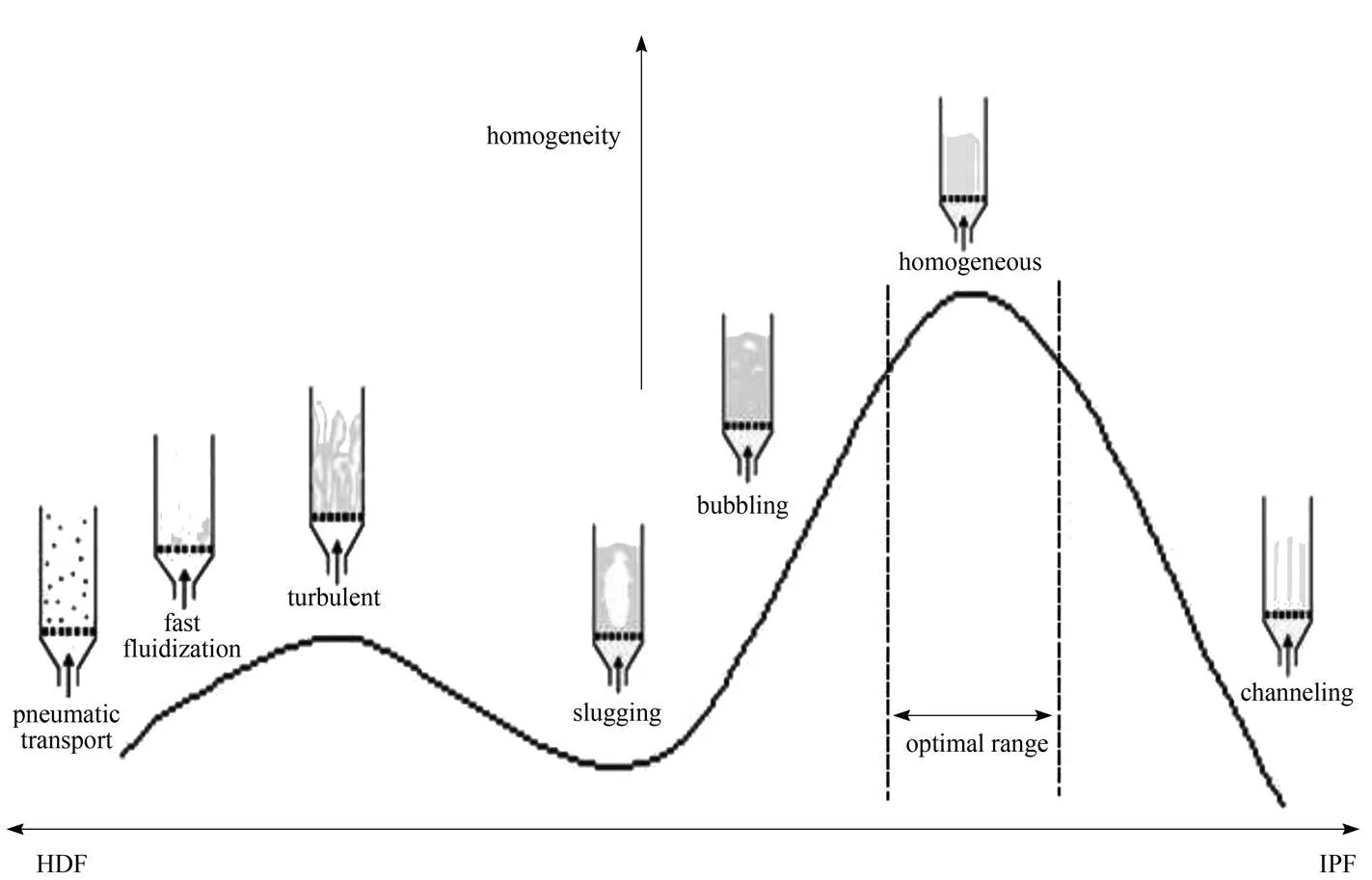
Figure 2 A schematic showing the interaction between HDF and IPF
Figure 3 A bubbling bed with even bubbling, maldistribution and dead zones on a multiorifice plate [17]
3 BED CONFIGURATION IN PI THINKING
In practice, most fluidized bed configurations employ the straight cylindrical geometry due to their compactness. As one modification to the cylindrical geometry, conical beds create a decreasing velocity gradient along the axial of beds, which could potentially accommodate themfvariation of polysized particles in the same direction. Therefore, the conical geometry could somewhat relieve elutriation. Despite the nature of bed geometry in a fluidized unit may allow relatively narrow scope of design variations, there are indeed some other opportunities in this area for bed enhancements, which mainly involves gas distributor system and intrusive methods.
3.1 Gas distributor system
Choosing the types of gas distributor is a critical undertaking. Fig. 3 illustrates some operating problems associated with poor distributor design. To ensure a more uniform gas and bubble distribution, distributor designs generally feature small size pores with uniform distribution and high distributor/bed pressure drop ratio (>0.3). Nevertheless, the effective region of a typical gas distributor only persists to a certain height above the distributor, especially at high gas velocities. Driven by overcoming the axial depth limit of distributor effectiveness and radial inhomogeneous flow structure, there were several types of attempts regarding intensification of the original distributor system in the literature, including, but probably not limited to, (1) pulsating gas flow, (2) multi-staged swirler nozzles, and (3) using different types of inclined gas injection.
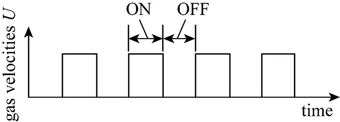
Figure 4 A schematic of square wave of gas pulsation
3.1.1
Several early works recognized that periodical gas flow pulsation can notably improve the fluidization quality, including the channelling or gas bypassing reduction [18, 19]. The original pulsation induced in early works employed square waves (see Fig. 4), which are operated in a periodic ON/OFF mode with a single solenoid valve. The initial bubble size reduction mechanism can be attributed to smaller bubble detachment from the distributor during the OFF period, when the pulsation frequency was higher than the bubble formation frequency. The ratio of the ON to OFF period is one key factor in this type of pulsation, as the initial bubble size generally increases with it. The switching frequency is another important factor. As the frequency increases, Massimilla. [18] distinguished three types of fluidization behaviour: intermittent fluidization, piston-like fluidization, and normal or plain fluidization. This discovery was indicative of an optimal frequency range. Among the first, Wong and Baird [19] claimed that the effect of pulsation was maximized when it resonated with the natural frequency of the bed. In their study, the authors also proposed a piston model to predict this frequency, however, based on two hypotheses of a single homogenous fluidized medium and no bed support effects. The most recent application of gas pulsation [20] took the form of sinusoidal waves, with the time-averaged superficial gas velocity set abovemfand the instant gas velocity always above zero. A smaller and more regular bubble pattern was observed. Compared with the square wave pulsation, there was no gas OFF phase, so the solid mixing could be improved along with better heat transfer, higher controllability of both conversion and selectivity of transport limited chemical reactions.
The gas flow pulsation technique is also anticipated to be effective for the elutriation reduction of small-sized particles fluidization as the size of bubbles bursting on the bed surface decreases. At the moment, there are some practical challenges to its industrial applications, of which the most significant is the pulse attenuation and wall effects in deep beds, as one would expect, the pulsation-induced regular flow patterns only persist to a desirable height in shallow or low/beds.
3.1.2
Swirling gas flow is a natural occurrence in many practical applications, such as gas turbine engines, jet pumps, spraying machines and vortex cyclone separators. Utilizing intense swirling flow to obtain excellent elutriation control in fluidized beds is also well documented as a design of swirling fluidized bed combustors (SFBC) [21]. Most SFBCs feature multiple swirler nozzles on wall positioned at certain heights, in which the gas is blown into the combustor at a certain angle, as well as from the primary bottom distributor. The axial-plus-tangential gas stream can generate a swirl flow of core-annular structure [22] and centrifugal force, which can form relatively stable annular suspension layers of particles. Fig. 5 illustrates the formation of suspension layers, which circulate in a circumferential direction[23] and alternate with dense (lower suspension layer) and dilute (higher suspension layer) zones along the centreline[24]. The elutriation of fine particles from lower section is captured in these suspension layers when passing through the upper body (freeboard) of the beds, which consequently improves combustion efficiency and pollution control by increasing particles residence times. As a result, one striking benefit is that the height or volume of the freeboard and collecting cyclone is greatly reduced with a more compact reactor. This also opens the perspective of multifunctionality in a single vessel, as the suspension layers can potentially serve as sorbent carriers for by-product gases filtering in some fluidized bed applications,.. SO, NO, CO in coal combustion, CO2in hydrogen generationbiomass gasification.
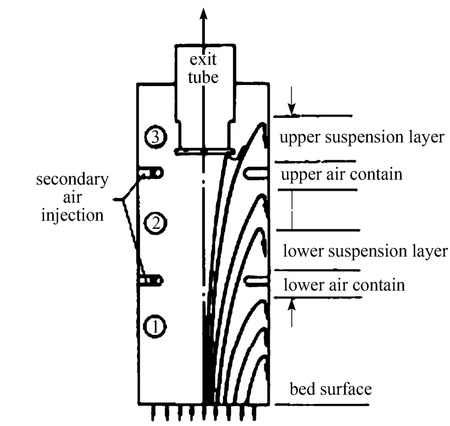
Figure 5 A schematic diagram of the formation of suspension layer
The swirl number,, defined as the ratio of tangential flux momentum to axial flux momentum, is widely employed to characterize the intensity of swirl flow in this design:
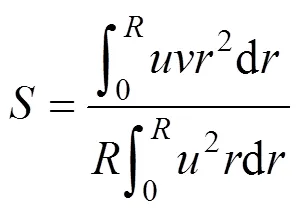
whereis the axial velocity,is the tangential velocity, andis the bed radius. Essentially, this number is influenced by nozzle design parameters, such as nozzle number, the diameter of the nozzle opening, the arrangement of nozzles, and injection angles. Evidently, increased number of nozzles and reduced nozzles diameter increase[25]. Lee. [26] conducted an experimental study on relationship between the swirl intensity and combustion efficiency. They reported that the combustion efficiency was proportional to, as the entrapment of fines in upper stage increased with. Nieh. [24] reported that as the swirl number increase from 0 to 4.34, the gas recirculation rate increased notably, and the elutriation rate decreased by 5 orders of magnitude within the experimental conditions. Optimal effect of secondary air injection was obtained when gas was injected at the angle of 45°.
Other design and process parameters,.. optimal secondary gas velocities, nozzles height and types, have also been explored. As even high tangential secondary gas might potentially increases the elutriation of fines, there should be an optimal range of operating gas velocities for secondary gas flow. This was supported by Lee’s observation, in which trapping effects of fines in upper stage reached their maximum at tangential gas velocities between 18 m·s-1and 24 m·s-1[25, 26]. Lin. [27] further suggested that in order to achieve higher combustion efficiency, the location of the secondary air injection should be kept lower in the region above the bed expansion section, but at a higher position for the region below the bed expansion section. Bed combustion efficiency as high as 96% was reported in such configuration. Nieh and Yang [28] investigated two different types of nozzles and reported that protruding injection nozzles proved superior to peripheral air injection at the wall. It indicated that a more intense swirl flow near the core region is beneficial in SFBC design. However, a further investigation into the depth of protrusion is still needed to fully justify this improvement. The current challenge associated with the SFBC design is how to maintain the effective swirl intensity throughout the length of the bed in large-scale applications. This needs an in-depth knowledge of the swirl decay process in these designs, which, however, has not been established yet.

Figure 6 (a) A spiral gas distributor [30] and (b) inclined blades array in a Torbed
3.1.3
Using inclined gas injection to improve the radial gas mixing is well documented in the literature, including sloping distributors, which was aimed at creating so-called ‘whirling’ bed [29], ‘Conidur’ plate distributors, which feature two semi-circular plates welded along the diameter, swirling distributor, where the swirling gas motion was generated by a multi-horizontal nozzle distribution in the plate and spiral distributor, which consist of gapped blades overlapping at certain angles[30]. Among these enthusiastic quests is a state-of-art design, Torbed, which was invented during the 1980s by Torftech, UK. The basic design of a Torbed features an annular ring of stationary blades or vanes as a distributor, which mimics a static set of turbine blades. As an improvement version of the spiral distributor [see Fig. 6 (a)], a Torbed have a centrally located hollow cone, instead of the overlapping blades being welded together at the centre [see Fig. 6 (b)]. This modification could eliminate the potential formation of dead zone at the central area and offer the advantages found in conical beds. The potential disadvantages associated with Torbed design might arise from the non-uniform particle distribution, which is generally high near the wall side. With respect to its configuration, inclined blade angle and the ratio of annular width to bed radius merit further research interests, as the former undoubtedly have deciding effects on the generated swirling intensity and the latter could influence the variation of centrifugal force along the radius.
3.2 Process intensification using intrusive methods
The default configuration for a fluidized bed consists of a bed and gas distributor. Nevertheless, it is not common for a practical fluidized bed unit to be an empty space containing fluidized particles, where different types of intrusive objects are usually present. In industry practice, fluidized-bed reactors commonly contain immersed heat exchanger tubes containing circulating steam or coolant for the control of their operating temperature. The presence of tube bundles could potentially increase the vertical through-flow gas velocity, which could account for appearance of bubble elongation, improved gas-solid contacting with less gas backmixing and increased radial particle mixing[31]. The bubbles usually slide off the tube when they encounter it and would not split unless the bubble size is larger than the tube and directly collide with it [32]. However, even in the latter situation, an alternating sequence of bubble splitting and coalescence usually appeared at the surface of the tubes or a short distance above them [33]. As a consequence, bubble number and size distribution was not greatly affected by the presence of tube arrays. Although a larger effect was achievable by increasing the density of the tube array formation, the reduced solid motion due to the direct obstruction is anticipated to be higher, which is in turn detrimental to the bed-to-surface heat transfer. We shall clarify that only horizontal configurations of tube array are considered here, as the vertical configurations aid the undesirable slugging.
3.2.1
Another early example of intrusive methods in industrial applications featured several horizontal- oriented grids or mesh type baffles to stage the fluidized bed and control elutriation [34], which was particularly useful for slow reactions, or when an adequate concentration of fines cannot be maintained. Tweddle. [35] further suggested the baffle should be positioned only up to the surface of a dense bed to maximize the effectiveness on elutriation control. The effectiveness of this type of baffle on bubble breaking and slugging reduction was also well noted. A systematic experimental investigation on a wide range of different types of baffles (29 in total) initiated by ABB Lummus-Crest demonstrated the smooth fluidization of a pilot-scale unit (25 cm i.d. ×300 cm high) [36]. However, as the solids mixing is impeded continuously from the feed to the exit of the fluidized bed [37], such designs usually require careful plate design (.. mesh size, baffle arrangements) to ensure smooth operation without any solids feed imbalance between the stages and thus simultaneous fluidization of all bed compartments.
There are also some other intrusive objects, which do not essentially fit in the aforementioned categories but possess certain abilities in elutriation control. For example, a sophisticated design called diverter was operated with more than 80% reduction in elutriation, although the pressure drop was reported to be undesirably high [38]. Most recently, a novel design with arrays of parallel inclined plates in the freeboard was utilized to control elutriation by increasing the effective fines sedimentation area [39]. However, few of the more complex geometries were found to be particularly superior to the simple shape in the previous studies.
The preceding review of intrusive methods is by no mean a complete summary, especially when considering the colossal number of industrial fluidized beds operating with internal not reported in the open literature. Nevertheless, some marked characteristics of these horizontal intrusive objects can be concluded: (1) Overall pressure drop is usually anticipated to be higher; (2) Depending on applications, compromise between solid mixing (.. heat transfer) and bubble suppression is always necessary; (3) Defluidization zones or dead spots on the upper surface of intrusive objects often occurs; and (4) severe erosion and difficulty of emptying the fluidized particles from a bed. Taken altogether, it is effective to say that the effects of intrusive objects reviewed above on overall bed hydrodynamics are limited, especially in the proposed PI niches. Next, one successful industrialized design containing intrusive objects, an internal circulating fluidized bed (ICFB) is described in more detail, in which a reactor vessel is partitioned by a vertically positioned draft tube with striking multifunctionality.
3.2.2
The invention of circulating fluidized bed (CFB) in the early 1940 s allow commercial units operating in turbulent or fast regime with large throughput and without massive elutriation. However, it is well known that old-fashion CFB designs have some intrinsic weaknesses, such as requirement of a higher riser as a reactorand an accompanying tall cyclone as a collector, which undermines its compactness and mobility, and thus increases construction costs. As a further development of the traditional CFB, the internal circulating fluidized bed (ICFB) design solves the same particle retention and elutriation problem, but more importantly with reduced freeboard height [40]. Fig. 7 illustrates some marked difference between the two configurations.
Figure 7 Comparison of the characteristics of ICFB with CFB
The first application of internal circulating fluidized bed (ICFB) was to assist reclamation of foundry sand at the pilot scale level by the Gas Technology Research Group of Ecole [41] and they are now widely used in thermal treatment of industrial solid wastes, contaminated soil, electrodes from the aluminium industry, industrial sludge including the pulp and paper deinking sludge, sludge from waste water purification and petroleum reservoirs, and other divided solid waste [42-44]. So far, one application that has received some fundamental studies is coal gasification[45]. The draft tube divides the bed or gasifier into three distinct aeration zones: a draft tube as one combustion bed with air feeding, an annular zone as one gasification bed with steam feeding and a disengagement zone over the top [46]. Within a typical ICFB gasifier, the tube and annulus region operate at different gas velocities. As a result, the circulation of particle flow was facilitated due to pressure difference between the draft tube and annular zone with the particle trajectory upwards in the draft tube and downwards in the annulus region. As one would expect, a higher circulation rate could be achieved by using a larger ratio of tube diameter to annulus width.
However, set against the advantages, gas bypassing from the draft tube area to annulus area was considered as one of most negative factors, because this would cause dilution and burning of the product gas from gasification and consequent degradation of its quality [47]. Some authors proposed to control the gas bypassing by changing the inlet geometry or design of the draft tube. For example, it is widely agreed that tapered bottom of annular section could effectively reduce gas bypassing. Song. [48] concluded that the higher the draft tube is and the shorter the gap height is, the smaller the gas bypassing. Kim. [47] reported that under the same particle circulation rate, the gas bypassing from the draft tube to the annulus region was reduced by switching the type of draft tube from gap height to orifices. Due to the long and narrow shape of tube and annulus region, potential slugging occurrence could pose another challenge, which has not received any research attentions yet.
With no auxiliary gas injection in the annular region, Mleczko and Marschall [49] illustrated several different hydrodynamics regimes as gas velocity increased by interpreting the bed pressure drop. Most importantly, the regime of stable circulation was observed only over a narrow range of gas velocities. This discovery suggests the delicate nature of successful operating an ICFB system. However, it is still largely unknown how to determine this narrow gas velocity range with optimal solids circulation rates and less elutriation, as most of the studies or applications chose to ignore this by utilizing a baffle separator or impact device directly over the top of the draft tube.
4 APPLICATION OF EXTERNAL FORCES
The original Geldart classification scheme only applies where the ‘plain fluidization’ (normal temperature and pressure and in the earth gravitational field) is possible, whereas the ratio of IPF to HDF should be considered the real deciding factor in determining the boundary of fluidization regime or behaviour. In this section, five external force assistances in forms of mechanical, acoustic and electromagnetic agitation are reviewed, which have been employed in the literature to directly manipulate IPF by introducing additional forces between fluidized particles. Three inherent strengths associated with all these types of external force enhancements to fluidized bed design can be derived from the published studies:
(1) External force-assisted fluidized beds are the most effective in the absence of any internals, so that the issue of severe erosion or wear can be avoided to the large extent.
(2) Under specific circumstances, they all possess a superior ability to facilitate cohesive or nano-sized particles fluidization, which somewhat substantiate the capacity of the concept of applying external forces in altering IPF.
(3) They all exhibited excellent potential for downsizing effect or compactness to different degrees, however, usually at the expense of complexity in both design and operation. This in part explains their rare introductions into the industrial practice.
4.1 Centrifugal field

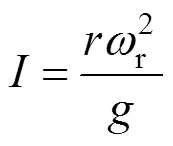
As the inwardly injected gas travels towards the bed centre, its velocity increases because of the progressively reduced area of flow, as does the value of. As a consequence, the initial fluidization commences at the inner surface where the drag force on the particles first counterbalances the centrifugal force, and proceeds rapidly outward as the gas velocity increases until eventually the whole bed is fluidized. This phenomenon also suggests two minimum fluidization velocities: one is called the surface minimum fluidization velocity,smf, while the other one is called critical minimum fluidization velocity,cmf, for the whole bed [51], as is illustrated in Fig. 8.

Figure 8 Transitions between different gas flow velocities [52]
There are several remarkable characteristics of a typical RFB hydrodynamics. First, the minimum fluidization velocity increases approximately linearly with the rotation speed [52] and could theoretically be fixed at any value. Accordingly, an RFB would potentially accommodate higher operational gas throughput in the absence of undesired elutriation, and thus it follows that the process can be intensified to a high throughput system. Levy. [53] found elutriation decreases when either bed mass or rotating speed is increased in an RFB containing a polydispersed glass bead mixture. Saunders [54] estimated maximum gas velocity without noticeable elutriation by correlating the ratio of fluidizing velocity to particle terminal velocity at the surface of the RFB. Second, a shift in the original boundary of Geldart grouped particles was observed under the influence of applied centrifugal gravity. Qian. [55] reported group C particles (7mm alumina) behave like group A or B particles in a centrifugal force-assisted fluidization.
Reported RFB applications in the literature include granulation of fine powders [56], sludge incineration/coal combustion [57], dust filter and catalytic reactor for clean-up of NOfrom diesel exhaust [58],. In recent years, RFB was also utilized in overcoming the difficulty of nanoparticle fluidization. Matsuda. [58] first fluidized ultrafine TiO2particles (7 nm) in the absence of bubble formation and large elutriation with assistance of centrifugal force (9, 16, and 37 g) in the literature. The nanoparticle agglomerates were observed to be smaller near the gas distributor region as the centrifugal force intensity,, increased. In a subsequent publication, they further investigated this centrifugal force-induced fragmentation of large agglomerates, and proposed a mathematical model based on an energy balance to predict the agglomerates size reduction [59]. Quevedo. [60] extended the range of investigated nanoparticles (12 nm Aerosil R974, 16 nm Aerosil R972 and 21 nm Aeroxide TiO2P25) in a horizontal RFB.
Compared with the aforementioned SFBC and Torbed, RFB is believed to create the strongest gravitational force on particles. Benefits associated with RFB include better control of elutriation, high gas-particle contact, low equivalent system mass in terms of compactness, low overall mass as in shallow beds and higher reliability than conventional static fluidized beds. Nevertheless, some practical concerns regarding industrial RFB applications should be noted, such as operation continuity due to the difficulty of particle feeding or removal through the fluidization chamber, and manufacturing difficulties of large scale rotating bed, including sealing between the rotating and stationary parts, mechanical vibration,.
4.2 Mechanical and acoustic vibration
4.2.1
The earliest studies of fluidization subject to vertical vibration showed particles could be fluidized by mechanical vibration energy alone without gas supply. For clarification, vibrating fluidized beds with aeration reviewed in this section are termed as vibrating gas fluidized beds (VFB). Most commonly, fluidized beds show negative bed expansion at lower frequencies and gas velocities due to transformation to a more compact state resulting from the downward movement in certain half of the vibration cycle.
It is well documented that with the assistance of vibrational energy, bubbling and channelling of group C or cohesive particles is remarkably reduced or diminished, andmfbecome lower. Therefore, applications of VFB to cohesive particle handling are more commonly seen in industrial processes, such as drying of granular solids, coating, granulation, and catalytic reactions [61, 62]. For most sinusoidal vibration, a vibration number,, can be introduced to evaluate the vibration intensity, which is defined as

Similar to what has been found in gas pulsation studies, there is an ideal stable fluidization state in which, when the vibration frequency is equal to the bednatural frequency, the bed expands rapidly to its maximum height at any given amplitude, and the mechanical agitation reaches its maximum level. Wang. [64] observed two separate resonance frequencies for the fluidized bed and base vibration, respectively, and further suggested that the stable fluidization state was the result of a synergy of vibration and gas velocity.
At the moment, significant vibrational energy dissipation in deep beds could be of great concern in industrial applications, since most of experimental studies were performed using shallow beds (<20 cm). Furthermore, operational difficulties and energy costs associated with vibrating heavy large-scale beds also pose a daunting task to its successful industrial application. With respect to the design, it is reasonable to contend that instead of restricting the vibration to the bed support or gas distributor, applying vibration over the whole bed could potentially be more productive in bubbling suppression. Horizontal vibration and the ratio of amplitude to bed diameter could also be of great interest to future research work, since most of studies were interested in the vertical orientation.
4.2.2
As early as 1955, a pioneering work by Morse [65] showed that the fluidization quality of cohesive particles (plaster of Paris and pigment) was enhanced by the application of sound waves generated from the bottom of a fluidized bed, though no effect on coarse granular particles was observed. In the literature, sonic waves were generated by sirens, whistles or loudspeakers, and ultrasonic waves were generated by piezoelectric crystals. Since the 1990s, the quantity of literature on sound-assisted fluidized beds has been growing rapidly, as its advantage in handling of ultrafines or nanoparticles have been gradually recognized. As one source of external energy, standing sound waves are believed to break up the large agglomerates formed by cohesive particles, thus enhancing fluidization state. Among the first, Montz and Beddow [66] investigated the effect of high-decibel acoustic fields (155 to 165 dB) in removal of contaminants from adhesive particles, and noticed that the intense turbulence induced by an acoustic field could significantly reduced the size of particles agglomerates [66]. The sound pressure level (dB),sp, is defined as:

The acoustic effects on bed hydrodynamics are heavily dependent on the parameters of the sound field,..spand frequency. Taking the effects of sound wave on agglomerates breakage as a standpoint, Chirone and Russo [67-69] presented a cluster-subscluster model assuming the rigid body of the agglomerates, later followed by an improved version, an elastic model to correlate the acoustic effects on fluidization behaviours (.. agglomerates breakage size, pressure drop, bed expansion,mf) withspand sound frequency. However, authors considered no sound attenuation effects as it propagated through the bed, which is particularly not suitable in deep beds condition. Despite the limitations to these attempts to predict the sound-assisted fluidized bed behaviour, it is evident that the highestspand maximum acoustic field effect would occur at a resonant bed frequency. By using particles of various size (4.8-65 µm) including Al2O3, TiO2, glass beads and FCC catalyst, Xu. [70] confirmed the existence of a resonant frequency of about 100-110 Hz within the experimental conditions. More recently, Herrera. [71] proposed a numerical model to calculate the natural bed frequency, assuming that the two phase gas-particle flow behave as a single homogeneous medium and all dynamics is one dimensional. With the consideration of the attenuation effect, they concluded it that the natural frequency of the bed is proportional to the speed of the sound and inversely proportional to the bed depth. Since the resonant state offers an ideal situation for achieving a maximumspwith a minimum source amplitude, there is enough room of significance (.. energy saving) for further improvements to this model to remove the hypotheses.
Despite no satisfactory numerical relationship achieved between parameters of sound field and its effect so far, years of experimental studies of sound-assisted fluidized bed has formed a ‘rule of thumb’, that is, low frequencies and highspacoustic fields could generally improve the fluidization quality of cohesive particles. Among those, most studies concluded that the critical value of sound frequency for cohesive particle fluidization should be around 200 Hz, and any frequencies above it could potentially result in undesirable bubbling. For fumed silica nanoparticles in the form of large 100-400 µm agglomerates, Zhu. [72] further reported that for sound frequencies above 2000Hz, the acoustic field barely showed any effect on fluidization. At a fixed sound frequency value within the critical range (<200 Hz), the positive effects of the acoustic field (.. lower elutriation rate and lower minimum fluidization velocity) became more evident in higherspvalues (>100 dB), which is indicative of a threshold value for the initiation or maintenance of the smooth fluidization [73]. This existence of threshold value was later confirmed by Levy and Herrera [74], who demonstrated that onset of channelling appeared atspvalues below 146 dB. The authors further demonstrated an upper threshold ofspvalue (around 155 dB), while any value above it would also result in larger bubble sizes and greater bubbling. These discoveries emphasize the importance of choosing appropriate operational conditions in sound-assisted fluidized beds.
The viability of its application is severely restricted to fine particles, as the magnitudes of sound-induced vibrational energy in most studies are intrinsically smaller than the gravitational force as the fluidized particles became larger. In extreme cases of group D particle fluidization, the effect of acoustic field was almost unobservable or detectable with capacitometer. The inevitable sonic energy attenuation throughout the beds could further limit its popularity in industrial applications. With respect to acoustic field configuration, whether the acoustic field is transverse or collinear with the gas flow and generated at the bottom or over the top should also be addressed. The bed dimensions and the distance between the bed surface and the sonic source could also play a part in the acoustic effects on fluidization behavior, while the relevant study is scarce.
4.3 Electromagnetic field
Agbim. [75] first recognized that the natural occurrence of microscopic electrostatic forces in resin particles (125 µm) and magnetic forces in coarse steel shot, as two forms of IPF, could have positive effects on bubble suppression in fluidized beds. This discovery was soon followed by extensive studies aimed at altering IPF and its effects associated with an electromagnetic field.
4.3.1
In absence of an electric field, natural electrostatic effects in a fluidized bed and their accumulation are ubiquitous, due to frictional or contact electrification during inter-particle collision. This could cause particle adhesion to the walls of beds and other equipments, the agglomeration of particles into larger clusters, and in extreme case a fluidized bed transition into a channelling bed [76]. As a result, early electrical field applications were to collect the pollutants in the form of fines, since the field strength was not intense enough to have significant effects on the beds hydrodynamics. A more recent study in this direction reportedly controlled the elutriation fines with up to 96% efficiency, which highlights a possibility for remarkable freeboard reduction [77].
In a typical electro-fluidized bed (EFB), there are a number of governing parameters including voltage (V), gas velocity, particles properties (.. size, density and conductivity), field strength (kV·m-1) and relative humidity. Among these, the conductivity of fluidized particles is critical in determining the effect of the electric field. For a good conductor, the discharge effect of electrostatic accumulation is enormous with relatively modest field strength, or can even occur without it. For the insulating particles encountered in most early EFB applications, the natural electrostatic charge on fluidized particles is more or less uncontrollable. As for altering the bed hydrodynamics, both of them are far from being desirable as the fluidized materials. To overcome these shortcomings, applying more powerful DC electric field to directly alter the hydrodynamics of fluidized beds with semi-insulating particles became the focus of research interests after the 1970 s. For semi-insulating particles, the surface conductivity is high enough to remove the effects of natural electrification. However, when they are subject to an electric field, the surface polarization creates an attractive or repulsive inter-particle force, which leads to the formation of loose chains parallel to the field (see Fig. 9). In presence of these particle chains, reduced particle mixing and bed fluidity is observable, as well as limited formation, movement and coalescence of bubbles, which is of great research interests in the later studies.
Essentially, the electro-mechanical effects in the EFB system of semi-insulating particles enable a delicate equilibrium between electrical force-induced chain formation and HDF induced chain breaking. As the field strength increases, the chances of these newly-formed particles strings becoming more rigid escalate, and in extreme cases the whole bed can become frozen in position, with occurrence of gas flow channelling. On the other hand, once the apparent hydrodynamics force and constant gravity become dominant, say when large particles (mm) are fluidized under high gas velocities, the overall electromechanical effects (.. strings formation) mentioned above could be diminished or even eliminated.

Figure 9 Polarization for semi-insulating particles
With respect to the configuration, electric fields were applied either collinear with or transverse to the fluid flow. Johnson and Melcher [78] investigated the stabilizing effect of a DC electric field (262 to 918 kV·m-1) in both configurations, using semi-insulating sand particles with a mean diameter of 0.5 mm. In experiments using a cross-flow configuration, distorted bubbles were distinctively shown by photographic images, and the bed was somewhat stabilized under the influence of particle strings, ultimately leading to a frozen state with high field strength. With minimum 1000 kV·m-1field intensity, they found the humidity caused a decrease in the stabilizing effect by influences on the surface conductivity of particles. For co-flow configuration with several grid dividers, some qualitative descriptions highlighted the disadvantages of this configuration over the cross-flow design. For example, once the field strength is high enough to form particle strings, it tends to favour the formation of channelling as these particles strings form in the direction of gas flow. Therefore, bubble appearance was elongated rather than flattened, and the homogenous fluidization regime was significantly shortened.
In later stages of EFB development, research studies seemed to be more interested in AC electric fields. Colver [79] contended that for the fluidization of fine particles (<125 µm), an AC electric field of magnitude 100-1000 kV·m-1is sufficient for bubble suppression. Up to date, several advantages of AC fields over the DC field have been addressed. One is less unappealing particle adhesion to electrodes. Another is that an AC field ensures more free movement of particles, which leads to enhanced fluidity instead of a ‘frozen bed’. Recently, motivated by those advantages, a novel bed configuration with alternating current (AC) cross-flow field (frequency 1-200 Hz and strength 0-800 kV·m-1) was rigorously studied by Kleijin van Willigen. [80, 81], which features groups of staggered thin wire electrodes (live and ground ones) in contact with the bed. For all the experiments using semi-insulating glass beads, bubble shape was visually flattened in the presence of electrical field, and bubble size reduction was most effective in the conditions with higher humidity, lower frequencies, and higher strength field strengths (>500 kV·m-1). For group A particles, up to a 25% reduction in bubble diameter was reported, whereas that for group B was increased to a remarkable 85%. They also identified the optimal ranges frequency and field strength for smooth fluidization within the experimental conditions [80]. Nevertheless, a method to determine this optimal range was not established in this study, which is certainly of utmost interest to its industrial applications.
Currently, one limitation to its large-scale industrial application was the energy loss due to the possible corona or arc discharge at higher electric field strength. Also, an increased build-up of particles adhering to the electrodes as humidity increases adds extra complexity to the process control in large-scale units.
4.3.2
The notion of coupling magnetic fields with a gas-solid fluidized bed was first suggested by Rosensweig [82, 83]. With respect to magneto-fluidized bed (MFB) configuration, there are numerous variations in reported experimental designs. For clarification, these variations could be roughly summarized into three categories. In the first, the magnetic field is generated either by AC and DC (including pulsed on-off mode) in Helmholtz electromagnetic coils. Difference is that the inter-particle attractions induced by magnetic forces are weak in an AC-generated magnetic field compared with those that are DC-generated [84]. In the second, the generated magnetic fields could be applied either transverse or collinear to the gas flow. Penchev and Hristov reviewed most of the works on both configurations in the introduction of their articles [85], and yet no clear indication as to which configuration was superior was obtained in their work. In the third, the magnetic field intensity was either uniform or non-uniform with a gradient. The gradient of the non-uniform magnetic field was controlled by a number of positioned solenoids. Rosensweig [83] pointed out that the non-uniform applied field locks the particles against each other and to the container wall, and prevents fluidization. As a result, its potential applications are confined to the elutriation control or collection. We shall clarify that most of studies reviewed here adopted the uniform magnetic field.
In a magnetic field, the mechanism of bubble suppression was found to be similar to that in an electric field: above the minimum fluidization velocity, magnetic particles under the influence of magnetized polarization tend to rearrange themselves into the chain arrays, which were expected to limit the bubble size (see Fig. 10). For the fluidization of purely magnetic or ferromagnetic particles, magnetic fields with intensity as low as 3978.875 A·m-1(50 Oe) demonstrated the ability to induce complete bubble stabilization or elimination, while those with high intensity (3978.875-7957.75 A·m-1,.. 50-100 Oe) gave arise to the occurrence of slugging. Arnaldos. [86] proposed a mathematical model for an MFB of particle mixture (nickel-silica, steel-copper and steel-silica) dynamics based on the same phenomenon, and argued for the possibility of a stabilizing effect of non-magnetic particles through maintaining a proper volume fraction of magnetic particles. Wu. [88, 89] substantiated this theory by observing the stabilizing effect in a small volume fraction magnetic particles mixture (1.416 mm iron shot 10% and 0.935 mm copper shot 90%) in magnetic field (4000-22000 A·m-1). The significance of this finding is that the benefits of MFB application are no longer limited to magnetizable particles. In addition, its industrial feasibility is also boosted by the ease of separating the target (non-magnetic) particles from the assistant (magnetic) particles. Other advantages arising from the stabilizing effect include an extended regime of homogenous fluidization, which can accommodate high gas throughputs (sometimes 10-20 times greater), and also reduced elutriation (theoretically, it would be completely eliminated when the bed was ‘frozen’).

To sum up, several disadvantages regarding electromagnetic fluidized beds should be noted. First, such designs would incur significant costs due to equipment complexity. Secondly, electromagnetic fields only affect a very restricted range of particles, compared to RFB, VFB and sound-assisted fluidized beds. Thirdly, the effectiveness of electromagnetic fields on bubble dissipation may also deteriorate as the bed volume increases. Some researchers maintain the electric fields might be superior to magnetic fields by being more energy efficient (as low as 50 W·m-3) [80]. As the range of particles usable in EFB is restricted to those that are semi-insulating, the low current density would relive the massive power dissipation in large-scale design. Fourthly, compared with some physical processes [93, 94], application of MFB to reactive processes is more difficult, because of the uncertainty with regards to the effect of magnetic particles on the chemical reactions themselves and the limited feasibility of reactions that involve a non-magnetic catalyst. Although the latter can be overcome by formulating catalyst with magnetic cores, the extra manufacturing costs incurred could offset its significance to a large extent. Therefore, except for few works on ammonia synthesis where magnetic particles themselves (iron) were used as catalysts [95, 96] the investigations in this direction have shown little progress so far.
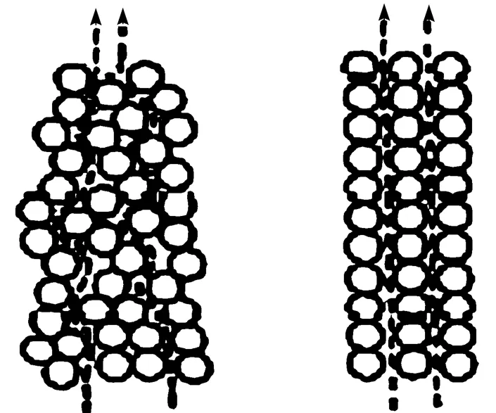
Figure 10 Arrangement of particles in the bed [86], and interfacial magnetic forces of opposing the ormation of non-magnetic voids in an MFB [87]
5 CONCLUSIONS AND RECOMMENDATIONS
To overcome the scale-up losses of fluidization quality due to bubbles and elutriation, various bed modification techniques in fluidized bed design have been reviewed. A PI perspective in terms of effective bubbling suppression and elutriation control has been adopted in an attempt to bridge the gap between different modification techniques and hopefully present a panoramic view of modified fluidized bed landscape. Collectively, these PI efforts in fluidized beds carried out so far have furnished a useful database for developing future advanced reactor systems. Some recommendations and conclusions can be drawn from this review as follows:
(1) Although few methods were effective by themselves enough to match up to the commercialized PI standard, especially the Ramshaw’s original “reductions on order of 100 times”, this review suggests that as far as bubbling suppression and elutriation control are concerned, it ought to be possible to gain improvements of between 2 and 4 times over conventional fluidized bed designs by the application of these techniques. At the moment, swirling gas flow generating techniques, including SFBC, Torbed, and RFB, is a fertile basis for the intensification of fluidized bed performance, especially in terms of bubble suppression and elutriation control. However, an in-depth understanding and comparison of the fundamentals of swirling fluid dynamics and its decay process in these techniques is still urgently needed to accelerate the successful PI solution in this promising area.
(2) It is not possible to specify a single type of modification technique that is optimum for all possible applications, even in terms of bubbling suppression and elutriation, as each application of the fluidization technique depends for its success upon difference properties of the bed to varying degrees. Combination of two or more modification methods is another likely path ahead. Therefore, comparative investigations should be developed and encouraged to examine the possibility of some complementary nature between different modification methods. There are already some studies reflected on this trend in the literature. In a typical VFB, reduced atmospheric pressure [97, 98] reportedly contributed to a more favourable fluidization state. More recently, effects of electric field coupled with vibration on nanoparticles fluidization was also investigated [99].
(3) To optimize a PI design, an intensive parametric study is commonly needed. Numerical simulation of modified fluidized beds using PI techniques reviewed heretofore has shown some progresses, such as gas pulsation [100-102], swirling fluidized bed [103], immersed tube arrays [104-106], internally circulating fluidized bed [107, 108], centrifugal fluidized bed [109-112], mechanical vibration fluidized bed [113, 114] and electrical fluidized bed [115]. It is envisaged that judiciously applying computer simulations in the future would provide an alternative design-screening with significant reduction of time cycle and building cost. However, it would be unrealistic to expect that one single simulation will address all problems at this stage. Adequate experimental validation is still necessary.
Finally, this review, particularly in its fundamental aspects, has to rely primarily on laboratory works in beds much smaller than those in commercial practices. This is in part because there are very few intensified designs have been commercialized, and also no studies have been made to evaluate their significances to existing industry-scale design. Nevertheless, we believe that the basic phenomena here described on the small scale are relevant in large equipments and may be scaled-up with reasonable confidence. On the other hand, published data on the operation of the commercialized large-scale intensified designs, for instance, Torbed, is generally scarce. As a consequence, systematic intensification of fluidized bed in academia and industry is still in the early stages. Cooperation efforts need to be called up from both fronts to build the prototype of successful process intensified fluidized bed reactor to demonstrate the strength of applying PI principles.
ACKNOWLEDGEMENTS
..
NOMENCLATURE
0vibrational intensity, Hz2
gravitational acceleration, m·s-2
centrifugal force intensity factor
spsound pressure level, dB
refthreshold value of human hearing (2×10⁻⁵Pa)
instantaneous fluid pressure
0equilibrium fluid pressure
swirling number
superficial gas velocity, m·s-1
cmfcritical minimum fluidization velocity, m·s-1
mfminimum fluidization velocity, m·s-1
smfsurface minimum fluidization velocity, m·s-1
rangular speed of rotation, rad·s-1
vangular frequency, s-1
1 Kunii, D., Levenspiel, O., Fluidization Engineering, John Wiley & Sons, US (1969).
2 Davidson, J.F., Harrison, D., Fluidization, Academic Press, US (1971).
3 Kwauk, M., Fluidization: Idealized and Bubbleless, with Applications, Ellis Horwood, New York (1992).
4 Molerus, O., “Interpretation of Geldart’s type A, B, C and D powders by taking into account interparticle cohesion forces”,., 33, 81-87 (1982).
5 Baeyens, J., Geldart, D., Wu, S.Y., “Elutriation of fines from gas fluidized beds of Geldart A-type powders-effect of adding superfines”,., 71, 71-80 (1992).
6 Steeneken, P.A.M., Woortman, A.J.J., Gerritsen, A.H., Poort, H., “The influence of flow conditioners on some mechanical properties of potato starch powder”,., 47, 239-246 (1986).
7 Seville, J.P.K., Clift, R., “The effect of thin liquid layers on fluidization characteristics”,., 37, 117-129 (1984).
8 Piepers, H.W., Cottaar, E.J.E., Verkooijen, A.H.M., Rietema, K., “Effect of pressure and type of gas on particle-particle interaction and the consequences for gas-solid fluidization behavior”,., 37, 55-70 (1984).
9 Bohle, W., van Swaaj, W.P.M., Fluidization, Davidson, J.F., Keairns, D.L., eds., Cambridge University Press, UK, 167 (1978).
10 Botterill, J.S.M., Desai, M., “Limited factors in gas-fluidized bed heat transfer”,., 6, 231-238 (1972).
11 Chitester, D.C., Kornosky, R.M., Fan, L.S., Danko, J., “Characteristics of fluidization at high pressure”,..., 39, 253-261 (1984).
12 Cui, H., Chaouki, J., “Effects of temperature on the local two-phase flow structure in bubbling and turbulent fluidized beds of FCC particles”,..., 59, 3413-3422 (2004).
13 Sunol, A.K., Kosky, J., Murphy, M., Hansen, E., Jones, J., Mierau, B., Sunol, S., “Supercritical fluid aided encapsulation of particles in a fluidized bed environment”, In: Proc. 5th Meeting on Supercritical Fluids, Nice (1998).
14 Liu, D.J., Kwauk, M.S., Li, H.Z., “Aggregative and particulate fluidization—The two extremes of a continuous spectrum”,..., 51, 4045-4063 (1996).
15 Vogt, C., Schreiber, R., Brunner, G., Werther, J., “Fluid dynamics of the supercritical fluidized bed”,., 158, 102-114 (2005).
16 Niu, F., Subramaniam, B., “Particle fluidization with supercritical carbon dioxide: Experiments and theory”,...., 46, 3153-3156 (2007).
17 Geldart, D., “The design of distributor for gas-fluidized beds”,., 42, 67-78 (1986).
18 Massimilla, L., Volpicelli, G., Raso, G., “A study on pulsating gas fluidization of beds of particles”,....., 62, 63-70 (1966).
19 Wong, H.W., Baird, M.H.I., “Fluidization in a pulsed gas flow”,..., 2, 104-113 (1971).
20 van den Bleek, C.M., Coppens, M.O., Schouten, J.C., “Application of chaos analysis to multiphase reactors”,..., 57, 4763-4778 (2002).
21 Zhu, S., Lee, S.W., “Co-combustion performance of poultry wastes and natural gas in the advanced swirling fluidized bed combustor (SFBC)”,, 25, 511-518 (2005).
22 Zhou, L.X., Li, Y., Chen, T., Xu, Y., “Studies on the effect of swirl numbers on strongly swirling turbulent gas-particle flows using a phase-Doppler particle anemometer”,., 112, 79-86 (2000).
23 Yang, G., Nieh, S., “On the suspension layers in the freeboard of vortexing fluidized beds”,., 57, 171-179 (1989).
24 Nieh, S., Yang, G., Zhu, A. Q., Zhao, C.S., “Measurement of gas-particle flows and elutriation of an 18 inch i.d. cold vortex fluidized-bed combustion model”,., 69, 139-146 (1992).
25 Lee, J.K., Lee, K.H., Jang, J.G., Shin, Y.S., Chun, H.S., “Effect of parameters on performance of two-stage swirl-flow fluidized bed coal combustors”,...., 24, 703-708 (1991).
26 Lee, J.K., Hu, C.G., Shin, Y.S., Chun, H.S., “Combustion characteristics of a two-stage swirl-flow fluidized bed combustor”,...., 68, 824-830 (1990).
27 Lin, C., Teng, J., Chyang, C., “Evaluation of the combustion efficiency and emission of pollutants by coal particles in a vortexing fluidized bed”,., 110, 163-172 (1997).
28 Nieh, S., Yang, G., “Particle flow pattern in the freeboard of a vortexing fluidized bed”,., 50, 121-131 (1987).
29 Baxerres, J.L., Haewsung, S., Gilbert, H., “‘Whiring Bed’: A new technique for gas fluidization of large particles”,..., 10, 191-197 (1977).
30 Ouyang, F., Levenspiel, O., “Spiral distributor for fluidized beds”,....., 25, 504-507 (1986).
31 Olowson, P.A., “Influence of pressure and fluidization velocity on the hydrodynamics of a fluidized bed containing horizontal tubes”,..., 49, 2437-2446 (1994).
32 Mojtahedi, W., “Effect of an immersed tub-tank in a gas fluidized bed”,.., 30 (6), 1095-1101 (1987).
33 Yates, J.G., Ruiz-Martinez, R.S., Cheesman, D.J., “Prediction of bubble size in a fluidized bed containing horizontal tubes”,..., 45, 1105-1111 (1990).
34 Overcashier, R.H., Todd, D.B., Olney, R.B., “Some effects of baffles on a fluidized system”,.., 5, 54-60 (1959).
35 Tweddle, T.A., Capes, C.E., Osberg, G.L., “Effect of screen packing on entrainment from fluidized beds”,....., 9, 85-88 (1970).
36 Dutta, S., Suciu, G.D., “An experimental study of the effectiveness of baffles and internals in breaking bubbles in fluid beds”,...., 25, 345-348 (1992).
37 Pydisetty, Y., Krishnaiah, K., Varma, Y.B.G., “Axial dispersion of solids in spiral fluidized beds”,., 59, 1-9 (1989).
38 Saunders, J.H., Chao, B.T., Soo, S.L., “Performance of a device for entrainment reduction and smoother operation of a fluidized bed”,., 35, 233-239 (1983).
39 Callen, A., Moghtaderi, B., Galvin, K.P., “Use of parallel inclined plates to control elutriation from a gas fluidized bed”,..., 62, 356-370 (2007).
40 Kim, Y.T., Song, B.H., Kim, S.D., “Entrainment of solids in an internally circulating fluidized bed with draft tube”,..., 66, 105-110 (1997).
41 Mukadi, L., Lavallee, R.J., Legros, R., Guy, C., “Development of an internally circulating fluidized bed combustor for treatment of industrial solid wastes”, In: Proc. 14th Int. Conf. FBC, ASME, 627-632 (1997).
42 Milne, B.J., Behie, L.A., Berruti, F., “Recycling of waste plastics by ultrapyrolysis using an internally circulating fluidized bed reactor”,..., 51, 157-166 (1999).
43 Benali, M., Guy, C., Chaouki, J., “Thermal treatment of divided solids by gas-contact process”,..., 31, 277-284 (1992).
44 Lovett, S., Berruti, F., Behie, L.A., “Ultrapyrolytic upgrading of plastic wastes and plastics/heavy oil mixtures to valuable light gas products”,...., 36, 4436-4444 (1997).
45 Lee, J.M., Kim, Y.J., Kim, S.D., “Catalytic coal gasification in an internally circulating fluidized bed reactor with draft tube”,..., 18, 1013-1024 (1998).
46 Berggren, J.C., Bjerle, I., Eklund, H., Karlsson, H., Svensson, O., “Application of chemical and physical operations in a circulating fluidized bed system”,..., 35, 446-455 (1980).
47 Kim, Y.J., Lee, J.M., Kim, S.D., “Coal gasification characteristics in an internally circulating fluidized bed with draught tube”,, 76, 1067-1073 (1997).
48 Song, B.H., Kim, Y.T., Kim, S.D., “Circulation of solids and gas bypassing in an internally circulating fluidized bed with a draft tube”,..., 68, 115-122 (1997).
49 Mleczko, L., Marschall, K.J., “Performance of an internally circulating fluidized-bed reactor for the catalytic oxidative coupling of methane”,..., 75, 610-619 (1997).
50 Mutsers, S.M.P., Rietema, K., “Gas-solids fluidization in a centrifugal field. The effect of gravity upon bed expansion”,., 18, 249-256 (1977).
51 Chen, Y.M., “Fundamentals of a centrifugal fluidized bed”,., 33, 722-728 (1987).
52 Kao, J., Pfeffer, R., Tardos, G.I., “On partial fluidization in rotating fluidized beds”,., 33, 858-861 (1987).
53 Levy, E.K., Shakespeare, W.J., Tabatabae-Raissi, A., Chen, J.C., “Particle elutriation from centrifugal fluidized beds”, In: 72nd Annual AIChE Meeting, San Francisco, CA (1979).
54 Saunders, J.H., “Particle entrainment from rotating fluidized beds”,., 47, 211-217 (1986).
55 Qian, G., Bagyi, I., Burdick, I.W., Pfeffer, R., Shaw, H., Stevens, J.G., “Gas-solid fluidization in a centrifugal field”,., 47 (5), 1022-1034 (2001).
56 Watano, S., Imada, Y., Hamada, K., Wakamatsu, Y., Tanabe, Y., Dave, R.N., Pfeffer, R., “Microgranulation of fine powders by a novel rotating fluidized bed granulator”,., 131, 250-255 (2003).
57 Wong, W.Y., Nasserzadeh, V., Swithenbank, J., “Experimental investigation into the incineration of sludges in a novel rotating fluidized bed”,..., 73, 143-160 (2000).
58 Matsuda, S., Hatano, H., Kuramoto, K., Tsutsumi, A., “Fluidization of ultrafine particles with high G”,...., 34, 121-125 (2001).
59 Matsuda, S., Hatano, H., Muramoto, T., Tsutsumi, A., “Modeling for size reduction of agglomerates in nanoparticle fluidization”,., 50, 2763-2771 (2004).
60 Quevedo, J., Pfeffer, R., Shen, Y., Dave, R., Nakamura, H., Watano, S., “Fluidization of nanoagglomerates in a rotating fluidized bed”,., 52, 2401-2412 (2006).
61 Kuipers, N.J.M., Stamhuis, E.J., Beenackers, A.A.C.M., “Fluidization of potato starch in a stirred vibrating fluidized bed”,..., 51, 2727-2732 (1996).
62 Suzuki, K., Fujigami, A., “Characteristics of vibro-fluidized bed for drying of wetted agglomerated particles”,...., 13 (6), 495-498 (1980).
63 Nam, C.H., Pfeffer, R., Dave, R.N., Sundaresan, S., “Aerated vibrofluidization of silica nanoparticles”,., 50, 1776-1785 (2004).
64 Wang, Y., Wang, T.J., Yang, Y., Jin, Y., “Resonance characteristics of a vibrated fluidized bed with a high bed hold-up”,., 127, 196-202 (2002).
65 Morse, R.D., “Sonic energy in granular solid fluidization”,..., 47, 1170-1175 (1955).
66 Montz, K.W., Beddow, J.K., “Adhesion and removal of particulate contaminants in a high-decibel acoustic field”,., 55, 133-140 (1988).
67 Chirone, R., Massimilla, L., Russo, S., “Bubble-free fluidization of a cohesive powder in an acoustic field”,..., 48, 41-52 (1993).
68 Chirone, R., Massimilla, L., “Sound-assisted aeration of beds of cohesive solids”,..., 49, 1185-1194 (1994).
69 Russo, P., Chirone, R., Massimilla, L., Russo, S., “The influence of the frequency of acoustic waves on sound-assisted fluidization of beds of fine particles”,., 82, 219-230 (1995).
70 Xu, C., Cheng, Y., Zhu, J., “Fluidization of fine particles in a sound field and identification of group C/A particles using acoustic waves”,., 161, 227-234 (2006).
71 Herrera, C.A., Levy, E.K., Ochs, J., “Characteristics of acoustic standing waves in fluidized beds”,., 48, 503-513 (2002).
72 Zhu, C., Liu, G., Yu, Q., Pfeffer, R., Dave, R.N., Nam, C.H., “Sound assisted fluidization of nanoparticle agglomerates”,., 141, 119-123 (2004).
73 Levy, E.K., Shnitzer, I., Masaki, T., Salmento, J., “Effect of acoustic field on bubbling a gas fluidize bed”,., 90, 53-57 (1997).
74 Herrera, C.A., Levy, E.K., “Bubbling characteristics of sound-assisted fluidized beds”,., 119, 229-240 (2001).
75 Agbim, J.A., Nienow, A.W., Rowe, P.N., “Inter-particles forces that suppress bubbling in gas fluidized beds”,..., 26, 1293-1294 (1971).
76 Ciborowski, J., Wlodarski, A., “On eletrostatic effects in fluidized beds”,..., 17, 23-32 (1962).
77 Wang, J.S., Colver, G.M., “Elutriation control and charge measurement of fines in a gas fluidized bed with AC and DC electric field”,., 135, 169-180 (2003).
78 Johnson, T.W., Melcher, J.R., “Electromechanics of electrofluidized beds”,...., 14, 146-153 (1975).
79 Colver, G.M., “An inter-particles force model for AC-DC electric fields”,., 112, 126-136 (2000).
80 Kleijin van Willigen, F., van Ommen, J.R., van Turnhout, J., van den Bleek, C.M., “Bubble size reduction in electric-field-enhanced fluidized beds”,.., 63, 943-948 (2005).
81 Kleijin van Willigen, F., van Ommen, J.R., van Turnhout, J., van den Bleek, C.M., “Bubble size reduction in a fluidized bed by electric fields”,....., 1, A21 (2003).
82 Rosenweig, R.E., “Fluidization: Hydrodynamic stabilization with a magnetic field”,, 204, 57-60 (1979).
83 Rosensweig, R.E., “Magnetic stabilization of the state of uniform fluidization”,...., 18, 260-2691 (1979).
84 Steven, J.G., Siegell, J.H., Rosensweig, R.E., Mikus, T., Lee, W.K., “Magnetically stabilized fluidized beds with time-varying magnetic fields”,., 56, 119-128 (1988).
85 Penchev, I.P., Hristov, J.Y., “Behavior of fluidized beds of ferromagnetic particles in an axial magnetic field”,., 61, 103-118 (1990).
86 Arnaldos, J., Casal, J., Lucas, A., Puigjaner, L., “Magnetically stabilized fluidization: Modeling and application to mixtures”,., 44, 57-62 (1985).
87 Liu, Y.A., Hamby, R.K., Colberg, R.D., “Fundamental and practical developments of magnetofluidized bed: A review”,., 64, 3-41 (1991).
88 Wu, W.Y., Navada, A., Saxena, S.C., “Hydrodynamics characteristics of a magnetically stabilized air fluidized bed of an admixture of magnetic and non-magnetic particles”,, 90, 39-46 (1997).
89 Wu, W.Y., Smith, K.L., Saxena, S.C., “Rheology of a magnetically stabilized bed consisting of mixtures of magnetic and non-magnetic particles”,., 91, 181-187 (1997).
90 Zhu, Q., Li, H., “Study on magnetic fluidization of group C powders”,., 86, 179-185 (1996).
91 Lu, X., Li, H., “Fluidization of CaCO3and Fe2O3particles mixtures in a transverse rotating magnetic field”,., 107, 66-78 (2000).
92 Yu, Q., Dave, R., Zhu, C., Quevedo, J., Pfeffer, R., “Enhanced fluidization of nanoparticles in an oscillating magnetic field”,., 51, 1971-1979 (2005).
93 Jaraiz-M, E., Levenspiel, O., Fitzgerald, T.J., “The uses of magnetic fields in the processing of solids”,..., 38, 107-114 (1983).
94 Li, Y., Zhao, C., Wu, X., Lu, D., Han, S., “Aggregation experiments on fine fly ash particles in uniform magnetic field”,., 174, 93-103 (2007).
95 Ivanov, D.G., Shumkov, S.K., “Investigation of the heterogeneity of a fluidized bed of catalyst for the syntheses of ammonia in an electromagnetic field”,..., 15, 557-560 (1975).
96 Zrunchev, I.A., Popova, T.F., “Ammonia synthesis in a magnetically fluidized powdery catalyst bed under a low pressure”,., 64, 175-181 (1991).
97 Wank, J.R., George, S.M., Weimer, A.W., “Vibro-fluidization of fine boron nitride powder at low pressure”,., 121, 195-204 (2001).
98 Noda, K., Mawatari, Y., Uchida, S., “Flow patterns of fine particles in a vibrated fluidized bed under atmospheric or reduced pressure”,., 99, 11-14 (1998).
99 Quintanilla, M.A.S., Valverde, J.M., Castellanos, A., Lepek, D., Pfeffer, R., Dave, R.N., “Nanofluidization as affected by vibration and electrostatic field”,..., 63, 5559-5569 (2008)
100 Wang, X.S., Rhodes, M.J., “Pulsed fluidization—A DEM study of a fascinating phenomenon”,., 19, 142-149 (2005).
101 Wang, X.S., Rhodes, M.J., “Using pulsed flow to overcome defluidization”,..., 60, 5177-5181 (2005).
102 Gui, N., Fan, J., “Numerical simulation of pulsed fluidized bed with immersed tubes using DEM-LES coupling method”,..., 64, 2590-2598 (2008).
103 Zhang, W., “A numerical study of solid suspension layers in a swirl fluidized bed reactor”,....., 7, A15 (2009).
104 Rong, D., Mikami, T., Horio, M., “Particles and bubble movements around tubes immersed in fluidized beds-a numerical study”,..., 54, 5737-5754 (1999).
105 Rong, D., Horio, M., “Behavior of particles and bubbles around immersed tubes in a fluidized bed at high temperature and pressure: A DEM simulation”,.., 27, 89-105 (2001).
106 Gui, N., Fan, J., Luo, K., “DEM-LES study of 3-D bubbling fluidized bed with immersed tubes”,..., 63, 3654-3663 (2008).
107 Marschall, K.J., Meleczko, L., “CFD modeling of an internally circulating fluidized bed reactor”,..., 54, 2085-2093 (1999).
108 Tatemoto, Y., Niwa, Y., Takeshita, T., “Circulation of particles in a vibrated bed with an inner tube”,., 192, 279-286 (2009).
109 Zhu, C., Lin, C.H., Lin, G.H., Qian, G.H., Pfeffer, P., “Modeling of the pressure drop and flow field in a rotating fluidized bed”,..., 190, 1132-1154 (2003).
110 Ahmadzadeh, A., Arastoopour, H., “Three-dimensional numerical simulation of a horizontal rotating fluidized bed”,., 183, 410-416 (2008).
111 Nakamura, H., Watano, S., “Numerical modeling of particles fluidization behavior in a rotating fluidized bed”,., 171, 106-117 (2007).
112 Nakamura, H., Tokuda, T., Iwasaki, T., Watano, S., “Numerical analysis of particle mixing in a rotating fluidized bed”,..., 62, 3043-3056 (2007).
113 Limtrakul, S., Rotjanavijit, W., Vatanatham, T., “Lagrangian modeling and simulation of effect of vibration on cohesive particle movement in a fluidized bed”,..., 62, 232-245 (2007).
114 Tatemoto, Y., Mawatari, Y., Yasukawa, T., Noda, K., “Numerical simulation of particle motion in vibrated fluidized bed”,..., 59, 437-447 (2004).
115 Kleijn van Willigen, F., Demirbas, B., Deen, N.G., Kuipers, J.A.M., van Ommen, J.R., “Discrete particle simulations of an electric-field enhanced fluidized bed”,., 183, 196-206 (2008).
2008-06-18,
2009-06-22.
* To whom correspondence should be addressed. E-mail: zhangwei811017@hotmail.com
猜你喜欢
幼儿100(2022年19期)2022-06-23
大学教育科学(2022年3期)2022-05-26
民族文汇(2022年19期)2022-05-25
幼儿100(2022年11期)2022-03-15
幼儿100(2021年37期)2021-12-23
幼儿100(2021年35期)2021-12-06
幼儿100(2021年18期)2021-06-23
啄木鸟(2021年1期)2021-01-11
当代工人·精品C(2019年5期)2019-12-02
金秋(2018年6期)2018-01-27
 Chinese Journal of Chemical Engineering2009年4期
- Chinese Journal of Chemical Engineering的其它文章
- Challenges in Study of Single Particles and Particle Swarms*
- Removal of Uranium (VI) by Fixed Bed Ion-exchange Column Using Natural Zeolite Coated with Manganese Oxide*
- An Unsteady Heterogeneous Mass Transfer Model for Gas Absorption Enhanced by Dispersed Third Phase Droplets*
- Influences of the [Co2+]/[Co3+] Ratio on the Process of Liquid-phase Oxidation of Toluene by Air*
- A Comparative Study of the Performance of Symmetric and Asymmetric Mixed-conducting Membranes*
- Development on the Technique of Total Recovery of Benzoic Acid Residue