
Numerical Simulation of the Penetration of Fuel-filled Tank by a High-speed Projectile
2010-06-07 10:22
船舶力学 2010年9期
(College of Shipbuilding Engineering,Harbin Engineering University,Harbin 150001,China)
1 Introduction
Penetration of attacked targets by high-speed projectiles has always been an urgently concerned subject of both the departments of weapons development and engineering protection.However,previous researches mainly focused on the penetration of steel[1-2]and concrete[3-4]targets,spacecraft shield configuration[5-6].Published literatures with respect to dynamics of liquid-filled tank under the impact of high-speed projectiles are still rare so far.As the commonly used energy storage apparatus for the large machineries such as aircraft and surface warship,once fuel-filled tank is under attack,disastrous consequence is usually caused.Consequently,it has a great significance for the promotion of both the protective performances of fuel tank and lethality of the projectile to investigate the damage mechanism of the tank and the velocity decay characteristic of the projectile.
The penetration of fuel-filled tank by high-speed projectiles refers to the problems of transient impact,plastic flow of the material and fluid-structure interaction et al,so it is strongly nonlinear.In view of the restrictions of the experimental study[7]and limitations of the analytical method[8],and as well as the development of finite element method and computer technology,numerical simulation has been a widely accepted means of exploring the mechanism of penetration.In the present paper,by means of the dynamic finite element package ABAQUSEXPLICIT,the penetration of fuel-filled tank by a projectile is simulated.The velocity decay characteristic and interaction between the tank and fuel are analyzed,especially the effects produced by the fuel on the dynamic response of the tank by changing the height of the fuel free surface.
2 Numerical techniques
2.1 Equations of the fluid-structure interaction

During the penetration,the equations governing the fluid-structure interaction are as follows:where [Ms],[Cs]and [Ks]are structural mass matrix,structural damping matrix and structural stiffness matrix,respectively; [Mf],[Cf]and[Kf]are fluid mass matrix,fluid damping matrix and fluid stiffness matrix correspondingly;{d}and{p } are separately displacement of the structure and pressure of the fluid;{Fp}is the impact force of the projectile and [Ffs]is the quantity that describes the mechanism by which the fluid drives the structure;[Sfs]is the transformation matrix on all of the interacting fluid and structural surfaces.Combining the equations(1)and(2),the structural dynamic response and motion of the fluid can be obtained finally.
2.2 Computing model and scenario of penetration
To simplify the numerical model,the stiffeners and attachment structures of the tank are not taken into account in the calculations.The front and back walls of the tank both measured 600mm×600mm are the contact surfaces of the projectile with the tank during penetration,and the height of the tank is 400mm,with the thickness of all the walls of tank being 2.5mm;the projectile is composed of a cylindrical body and a hemispherical top,with the length and diameter of the cylindrical body are 30mm and 12.5mm respectively.The distance between the top of the projectile and the front wall of the tank is 50mm at initial time and the projectile moves in the direction of the line between the center of the front and back wall,with the tank being fixed rigidly on the bottom boundaries.
Since the projectile,tank and the fuel in it are all symmetrical geometry,half of the projectile,tank and fuel are modeled and the corresponding constraints on the symmetry plane are added,in order to reduce the computational cost.In the model,the projectile and tank are both described as Lagrangian parts and the fuel is described as Eulerian part;at the same time,the techniques of single-point integration and hourglass control are taken to better dispose the nonlinear problems of large deformation and material failure.The calculated results can be plotted symmetrically with the post-processing tool and half of the models of projectile and tank are shown in Figs.1 and 2.
Figs.1 and 2 are finite element models of projectile and tank.The top and body of the projectile are meshed with tetrahedral elements and hexahedral elements respec tively,and the tank is meshed with four-node shell elements.To give a clear view of the motion of the fuel in the tank during penetration,the Eulerian part is established with the size of 700mm×700mm×500mm,and the tank is located at the center of the Eulerian part,surrounded by the void meshes.The composed mesh lines of the projectile,tank and the fuel in it are shown in Fig.3.
2.3 Material model and failure criterion
With respect to the material model in the simulation,the Johnson-Cook hardening relation[9]is selected to model the materials of the fuel tank and projectile,which is probably the most widely used among those models accounting for equivalent plastic strain,equivalent plastic strain rate and temperature effects.Then the equivalent Mises stress is given by:
In order to more accurately describe the material failure in the zone around the impact point,the Johnson-Cook dynamic failure model which fits the Johnson-Cook material model well is employed.Based on the equivalent plastic strain of the element integration point,it is considered that the failure will occur if the damage parameter achieves 1.Then the failure criterion is prescribed as:

where σhis the hydrostatic stresses;d1~d5are the constants depending on the property of the material,which are usually acquired from related experiments.
The fuel in the tank is described by the Eulerian element in the ABAQUS,and the density,dynamic viscosity,bulk modulus and sound speed in the fuel are taken as 860kg/m3,8.8×10-3N·s/m2,2.3GPa and 1 635m/s respectively.The tank and projectile are made of 2024-T351 aluminum alloy and some high strength steel separately,and the corresponding parameters of the materials are shown in the Tab.1.
Tab.1 Material properties of 2024-T351 aluminum alloy and high strength steel
3 Results and discussion
To investigate the complicated mechanisms of the interaction among the projectile,tank and the fuel in it during penetration,a series of simulations is carried out in three cases,namely tank without fuel,tank filled 80%and 100%.
3.1 Dynamic process of the penetration
Taking into account the length and the dynamic mechanism between the cases of tank filled 80%and 100%being roughly the same,typical scenarios are analyzed during the penetration in the case of tank filled 100%.As shown in Fig.4,Fig.4(a)~(c)are the experimental results by Varas et al,and Fig.4(d)~(f)are the simulated results correspondingly.
金黄饱满有“绝招”——为了防御病虫害和直接接触农药,在幼果成长到一定程度时,果农必须小心翼翼地给每个芒果套上纸袋。讲究的是,不同的品种还要使用不同颜色的“防护衣”,如白色单层的纸袋套台农芒,黄色双层的纸袋套金煌芒等等。
Based on the differences of the dynamics and damage mechanisms of the tank,the dynamic process of the penetration is divided into three stages:namely initial shock,forming of cavity and expanding of cavity.(1)Initial shock:This stage will occur just the instant the projectile impacts the front wall of the tank;the velocity of the projectile falls sharply,and the lost kinetic energy of the projectile is mainly transformed into the kinetic energy and plastic deformation energy of the front wall,the kinetic energy of the fuel around the impact point and the energy of the initial high-pressure hemispherical shock wave.(2)Forming of cavity:During this stage,the velocity of the projectile decays in the form of a hyperbolic function,and its kinetic energy is partially transformed into fuel motion.Under the penetration of the projectile,the fuel near projectile path moving radially at a certain speed,resulting in a radial pressure field finally.Compared with the initial shock stage,the velocity of the fuel during this stage increases gradually and not impulsively as usually thought.(3)Expending of cavity:After the penetration of the projectile,the fuel continues to move radially under the inertia of the fuel until the pressure of the cavity is less than the pressure of the surrounding fluid,forming the cavitation cavity.
3.2 Velocity decay of the projectile
According to Newton’s second law,

where mpand Vpare the mass and velocity of the projectile,respectively;ρfis the density of the fuel;A0is the projected frontal area of the projectile;Cdis the drag coefficient[8]related to the Reynolds number,a value of 0.3 is taken here.
Integrating the equation(6)and combining the initial velocity condition,the velocity decay of the projectile during flying in the fuel is obtained:

here V0is the initial velocity of the projectile.
Based on the residual velocity of the projectile after the penetration of the front wall(viz.1 216m/s),the analytic solution of the projectile’s velocity in the fuel is acquired,denoted by the solid line in Fig.5.Generally,the simulated results show excellent agreement with the theoretical results,with the maximum relative error being 3.8%.At the beginning,the theoretical results are overestimated in contrast to the simulated results and they have a trend of departing from each other;afterwards,the decay of the simulated velocity slows down,and it exceeds the theoretical velocity at around 0.5ms.Finally,the projectile impacts the back wall of the tank with the velocity having a sudden decrease,and comparison between the simulated and theoretical velocity here does not make sense.The differences between the simulated and theoretical results are mainly attributed to the simplification of the theoretical model,considering the effects of the fuel on the projectile as a constant resistance(Cd=0.3)in the opposite direction of the projectile’s velocity.Actually,the resistance on the projectile during penetration in the fuel decreases with the decrement of the projectile’s velocity.Consequently,the resistance of the projectile is larger when the velocity is higher,then decays faster;while the velocity is relatively lower,the resistance decreases notably,and the decay of the projectile’s velocity slows down,exceeding the theoretical results finally.
The velocity of the projectile in various cases is compared in Fig.6.It shows that:(1)in the case of tank without fuel,the velocity of the projectile decays greatly when it impacts the front and back wall of the tank,but remains roughly unchangeable during flying in the tank;the loss of the projectile’s kinetic energy when it penetrates the front and back walls of the tank are 5 306J and 7 069J respectively,and the latter is larger than the former obviously.It is because that when the projectile penetrates the back wall,the velocity is comparatively slower,then the back wall around the impact point deforms to some extent,absorbing more energy;(2)In contrast to the case of tank without fuel,the loss of the projectile’s kinetic energy when it penetrates the front wall of the tank filled 80%and 100%are 7 377J and 7 942J respectively,increased by 39%and 49.7%separately;the velocity of the projectile decays in the form of a hyperbolic function when it flies in the fuel,and with the reduction of the velocity the decreasing tendency slows down;in the case of tank filled 100%,the kinetic energy of the projectile loses 6 684J when it impacts the back wall,decreased by 15.8%compared with the front wall.It is supposed that under the combined effects of the shock wave and motion of the fuel the back wall of the tank has been pre stressed to some degree,so it will fails easily;comparing the cases of tank filled with 80%and 100%,the curves of the projectile velocity have the same tendency but the latter decays faster.

In summary,the fuel in the tank has a great impact on the dynamic process of the penetration and the velocity of the projectile decays more and faster than the case of tank without fuel.Consequently,various kinds of protective structures with liquid-filled bull come forth recent years,which shows the great effect produced by the liquid on the energy absorption of the coming high-speed shrapnel.
3.3 Damage deformation of the tank
To sum the analysis above,the influences of the fuel in the tank are mainly reflected in that it can absorb more energy of the projectile and transform it to the deformation energy of the walls that contact it.In order to further investigate the interaction between the tank and fuel in it,the time histories of the displacement,stress and equivalent plastic strain of the node located 0.02m over the impact point are plotted,shown in Figs.8-10.
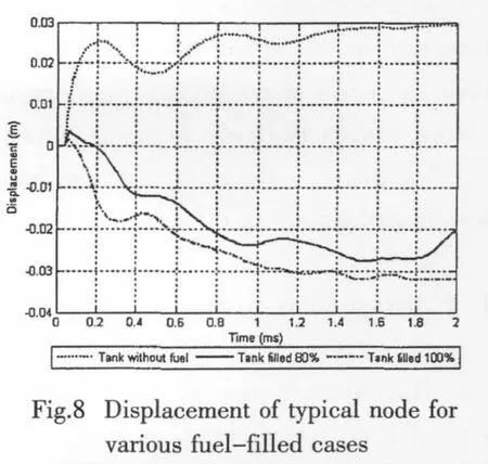
As shown in Fig.8,the motion model of the typical node in the case of tank without fuel differs from the other two cases obviously:In the case of tank without fuel,the tank walls deform in the same direction of the projectile’s motion,and the tank deforms further due to inertia until the kinetic energy is transformed into the deformation energy of the tank totally.The motion models of the cases of tank filled 80%and 100%are similar:At the instant of the beginning,the node has a displacement of 3mm in the direction of the projectile’s velocity,and then deforms outward under the impact of surrounding fuel;during the whole process,the deformation increases generally with slight oscillation,which may result from the elastic vibration of the tank itself and the coupling effects of the fuel.
The time-varying stress and strain of the typical node in the three different cases are shown in Figs.9 and 10.It can be found that the peaks of the stress in the three cases are roughly the same.However,in the case of tank without fuel,the stress will make a sudden drawdown sooner after reaching its maximum value,while the stress in the other two cases will remain at a high level in a long time,which is mainly caused by the motion of the fuel and the impulsive pressure in it.At the same time,the maximum equivalent plastic strain in the cases of tank without fuel,tank filled 80%and 100%are 0.34,0.38 and 0.40,respectively.So the maximum strain of the latter two cases has a promotion of 11.8%and 17.6%separately,compared with the case of tank without fuel.

In a word,due to the coupling effects generated by the fuel during penetration,the deformation model of the tank changes from localized inner concave to integral outer concave,while the scale of the crevasse gets smaller;the stress and strain of the tank have a great promotion,which is likely to result in a severe overall damage of the tank.Consequently,the coupling effects induced by the fuel must be fully taken into account in the structural strength design of the fuel-filled tank.
4 Conclusions
The dynamic process of the penetration of the fuel-filled tank by a high-speed projectile is simulated in this paper,and the main conclusions are as follows:
(1)Employing the dynamic finite element package ABAQUSEXPLCIT,which can handle the complicated problems including the nonlinearity of the material,geometry and fluid-structure interaction effectively,the dynamic process of the tank penetrated by a high-speed projectile is simulated successfully.
(2)Based on the differences of the dynamics and damage mechanisms of the tank during penetration,the whole process is divided into three stages:Initial shock,forming of the cavity and expanding of the cavity.
(3)The fuel in the tank has a great effect on the velocity decay of the projectile.Compared with the case of tank without fuel,the lost kinetic energy of the projectile in the case of tank filled 100%increases by 49.7%when the projectile impacts the front wall of the tank.While the lost kinetic energy decreases by 15.8%when the projectile impacts the back wall in contrast to the front wall in the case of tank filled 100%,owing to the pre stress induced by the motion of the fuel and impulsive pressure;the velocity decays in the form of a hyperbolic function during the projectile flying in the fuel,with the simulated results showing excellent agreement with the theoretical results.
(4)The fuel in the tank has a notable influence on the damage deformation of the tank.Compared with the case of tank without fuel,the deformation model of the tank changes from localized inner concave to integral outer concave,while the scale of the crevasse becomes smaller;the main effect of the fuel is reflected in the aspect of absorbing more kinetic energy of the projectile and transforming it to the deformation energy of the tank and it will make the stress and strain of the tank maintaining at a high level,resulting in an overall damage probably.
[1]Song W D,Ning J G.Mechanical model of rigid projectile penetrating stiffened plates[J].Journal of Ballistics,2007,19(4):43-46.
[2]Hou H L,Zhu X,Li W,Mei Z Y,Gong Z.Numerical analysis of perforation mechanism for a thin plate subjected to impact by hemispherical-nosed projectiles with low speed[J].Journal of Vibration and Shock,2008,7(1):40-45.
[3]Beppu M,Miwa K,Itoh M,Katayama M,Ohno T.Damage evaluation of concrete plates by high-velocity impact[J].International Journal of Impact Engineering,2008,35(12):1419-1426.
[4]Ge T,Wang M Y,Li X J,Pan Y F.Hydrodynamic model for concrete targets under impact of a projectile:Resistance and depth of penetration[J].Journal of Vibration and Shock,2008,27(1):107-110.
[5]Zhang W,Ma W L,Guan G S,Pang B J.Numerical simulation of non-spherical projectiles hypervelocity impact on spacecraft shield configuration[J].Explosion and Shock Waves,2007,27(3):240-245.
[6]Ding L,Zhang W,Pang B J,Li C A.Ballistic limit analysis for projectiles impacting on dual wall structures at hypervelocity[J].Chinese Journal of High Pressure Physics,2007,21(3):311-315.
[7]Varas D,Lopez-Puente J,Zaera R.Experimental analysis of fluid-filled aluminum tubes subjected to high-velocity impact[J].International Journal of Impact Engineering,2009,36(1):81-91.
[8]Gerhart P M,Gross R J,Hochstein J I.Fundamentals of fluid mechanics[M].Massachusetts,E.U.A:Addison-Wesley Publishing Co.1992,[Chapter8].
[9]ABAQUS Analysis User’s Manual[K].Version 6.8,Copyright 2008 ABAQUS,Inc.,2008.
猜你喜欢
分子催化(2022年1期)2022-11-02
今日农业(2021年10期)2021-07-28
河北果树(2020年4期)2020-11-26
37°女人(2019年9期)2019-12-16
电子制作(2019年15期)2019-08-27
表面工程与再制造(2019年6期)2019-08-24
测控技术(2018年9期)2018-11-25
食品工业科技(2014年7期)2014-03-11
中国果业信息(2012年2期)2012-01-24
- 船舶力学的其它文章
- Principle Study of Bubble Drag Reduction and Similarity Analysis for High Speed Vehicles
- Adaptive Inverse Control of Offshore Jacket Platform Based on Grey prediction and Rough Neural Network
- Effect of Internal Flow on the Dynamic Behavior of Top Tensioned Riser
- Helical Wave Spectra of the Radial Displacement of an Infinite Laminated Composite Cylindrical Shell Reinforced by Doubly Periodic Rings
- Active Control of Input Power Flow to the Cylindrical Shells
- Structure-borne Sound Attenuation in A Multi-corner Structure with Attached Blocking Masses