
Study on Outboard Inductive Damping Valve in Hydro-pneumatic Suspension
2011-03-09 11:57WANGXun王勋CHENSizhong陈思忠
Defence Technology 2011年1期
WANG Xun(王勋),CHEN Si-zhong(陈思忠)
(School of Mechanical and Vehicle Engineering,Beijing Institute of Technology,Beijing 100081,China)
Introduction
The damping coefficient of passive suspension is designed and optimized according to the requirement of the task.Once it is determined,it can not be adjusted for various roads and working conditions.The performance of suspension can not be improved further.But,the suspension with adjustable damping can choose proper damping coefficient to keep the ride comfort and driving safety as well[1].
The adjustable damping valve can be divided in four types,i.e.mechanical damping valve,electronic damping valve,ER & MR damping valve,piezoelectric damping valve.The inductive damping valve is one of the mechanical damping valves.It can adjust the damping to fit various road conditions and working conditions without electronic control system.It is also cheaper and reliable.
A hydro-pneumatic suspension system consists of accumulator,damping valve and cylinder.The pressure in hydro-pneumatic suspension is transferred by oil and nitrogen.In some hydro-pneumatic suspensions,the hydro-pneumatic spring serves as elastic and damping element without any special damping element.For most of vehicle’s hydro-pneumatic suspensions,the damping force is usually small and can not meet the requirements to reduce vibration rapidly for most offroad vehicles.In addition,this kind of damping force is difficult to be controlled and easy to be affected by the vehicle’s layout.The length of pipe connecting the cylinders will change the damping characteristics of the hydro-pneumatic spring.Therefore,it is necessary to design a special damping valve for the hydro-pneumatic suspension[2].
A new outboard inductive adjustable damping valve was designed for the hydro-pneumatic suspension of off-road vehicle.It is convenient to describe the working principle and external characteristic of this valve and analyze the dynamic characteristic of the vehicle by using the mathematical model proposed in this paper.
1 Working Principle and Structure of Outboard Inductive Damping Valve
The structure of the valve is shown in Fig.1.It consists of a fixed valve and a floating valve in series.The floating valve is suspended between two flexible compressing springs and can slide within a certain zone restricted by a limit block.For weak excitation from the road surface,the rebound and compressive valves in floating valve can not open because the floating valve does not reach its limit.The fluid can only pass through the fixed valve and generate the damping force.For strong excitations from the road surface,the rebound and compressive valves in floating valve open because the floating valve subjected to the fluid push reaches its limit.The damping force produced by floating valve will be added to the damping force produced by the foxed valve.Therefore,this damping valve is an inductive damping valve,which can detect the roughness of the road surface and adjust the damping automatically.
Both fixed and floating valves have rebound valve,compressive valve and bleeding orifice,respectively.In the compression stroke,the pressure difference between both ends of damping valve is too low to open the compressive valve when the beat speed of wheel is small.At this time,the oil can only pass through the bleeding orifices and enter into the accumulator.Therefore,the damping coefficient is larger because the bleeding orifice throttle area is very small.With the increase of the pressure difference between both ends of damping valve,the compressive valve opens progressively.Thus,the damping valve’s throttle area increases gradually.The damping coefficient reduces,but the damping force increases continuously.If the pressure difference increases further,the compressive valve opens maximally,then the damping valve’s throttle area does not change.Thus,the damping coefficient increases again and the damping force grows significantly.The characteristic in rebound stroke is basically the same with the compression stroke.But,the pressure drop to open the valve is larger so that the damping force in rebound stroke is bigger than that in the compression stroke.

Fig.1 Structure of outboard inductive damping valve
2 Mathematical Model of Damping Valve
In the outboard damping valve,the basic damping elements include bleeding orifices,rebound valves and compressive valves.Assume that the oil is steady,incompressible,its weight can be neglected,and the effects of exist in the leakage caused by the gap in damping valves and temperature on the oil characteristics can be ignored.In this paper,the relationship between pressure drop Δp and flow rate qvcan be obtained first,and then the damping force F= Δp·A can be found out,where A is the effective area of the cylinder piston.
2.1 Bleeding Orifice
The oil flow through the bleeding orifice can be expressed as
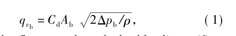
where qvbis the flow rate through the bleeding orifice,Abthe flow area of the bleeding orifice,Δpbthe pressure drop through the bleeding orifice,ρ the density of the oil,Cdthe discharge coefficient of the bleeding orifice.
2.2 Compressive Valve
The mathematical model of the compressive valve is a typical non-return valve model,as shown in Fig.2,where Acis the area of the single valve bore in the compressive valve,A1is the interaction area of valve disk with valve bore,K is the stiffness of pressing spring.

Fig.2 Sectional view of compressive valve
The oil flow through the compression orifice can be expressed as
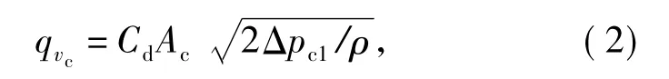
where qvcis the flow rate through the orifice of compressive valve,and Δpc1the pressure difference between both ends of the compressive valve.
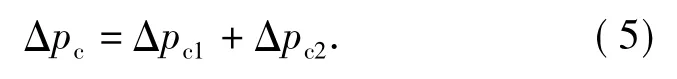
Based on Bernoulli's equation and the geometric relationship between valve disk and orifice bore,the flow rate can be written as
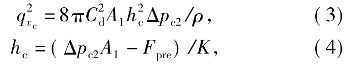
where Δpc2is the pressure drop at both ends of the compressive valve disk,hcthe opening height of the non-return valve disk and Fprethe preload of the nonreturn valve.
The total pressure drop over the non-return valve can be expressed as
2.3 Rebound Valve
The mathematical model of the rebound valve is a‘flat,faced,flapper’model,as shown in Fig.3,where r1is the inner radius of the valve bore,r2the outer radius,Rfthe distance between the valve’s centerline to the bore’s centerline,Rgthe radius of the gasket.When the valve opens slightly,the viscous force between the valve’s disk and seat is significantly larger than the oil’s inertia force.The flow rate qvis proportional to the cubic of the opening height hoof the valve and inversely proportional to the oil’s viscosity.Assume that the valve seat and disk are all smooth and the opening height of the valve is very small.

Fig.3 Sectional view of rebound valve
For the oil passing through the damping valve,the continuity equation can be written as

Its impulse equation can be expressed as

where v is the velocity vector of the oil flow through the valve,η the dynamic viscosity of the oil,Δpdthe pressure divergence of the oil when the rebound valve opens.
In cylinder coordinates,the velocity can be defined as
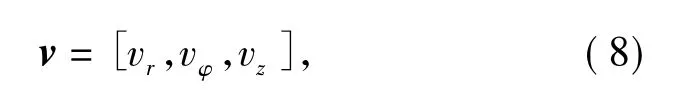
where vr,vφ,vzare the radial,angular and axial components of velocity,respectively,when the damping valve opens.
And,
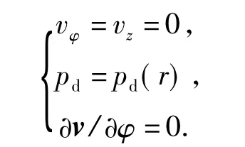
where pdis the pressure difference between both sides of the disk,and r the radius variable of the valve bore.
From Eq.(6)to(8),
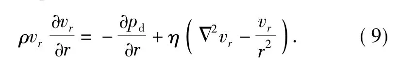
For a small bore,the inertia term is much smaller than the viscosity term and can be neglected.Thus,

Its boundary conditions are

From these conditions,the velocity can be calculated.
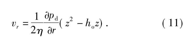
The oil flow passing through the rebound valve can be found out,

where m is the total number of valve bores,and qvrthe total flow rate of all rebound valve bores.
The force on the valve disk can be obtained,which consists of static and viscous forces,
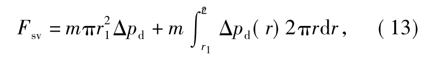
where Δpd=pd(r) - pd(r2).
Thus,
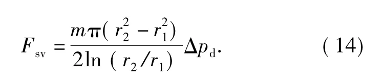
The equations above are only valid for small ho/(r2-r1),and in this case,the viscous force is much larger than the inertia force.For large ho/(r2-r1),the case is different[3-5],and the mathematical model will be a non-return model.Therefore,a large open of the valve has to be avoided.The next step is to obtain the relationship between the open height hoand the force F applied on the valve disk.For simple,assume that the force F is distributed linearly along radial direction.Then,
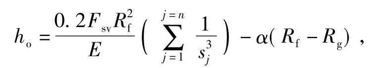
and

where E is the modulus of the valve disk,Fsvthe force in one of valve bores,α the angle of the valve seat and the valve disk,sjthe thickness of the jth valve disk,and ho<hmax.
If Eq.(15)is not fulfilled,the valve remains closed,and h=0.Combined Eq.(12),(14)and(15),and neglected the second-order term,we have

and
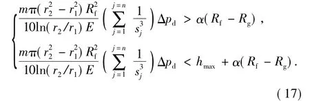
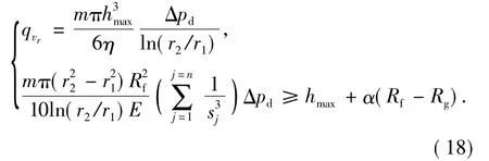
If Eq.(17)is not fulfilled,the valve can not open further.If ho=hmax,the relationship between Δp and qvwill become linear,that is,
2.4 Outboard Inductive Damping Valve
According to the working principle of the outboard inductive damping valve and the three mathematical models above,there are six states to analyze the characteristic of the valve,i.e.,the valve closes,opens partially and opens fully in compressing process,and the valve closes,opens partially and opens fully in rebound process.Because the structure of the fixed valve is similar to that of the floating valve,the characteristics of the fixed valve are analyzed only.
When the wheel beat and beat speed are all small in the compressing process,the oil can not flow through the floating valve,so only the bleeding orifice of the floating valve works.In this case,the damping characteristic can be expressed as
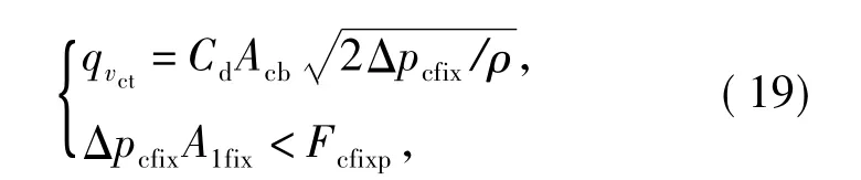
where qvctis the total flow rate through the inductive valve,Δpcfixthe total pressure between both ends of the fixed valve,Acbthe total area of the bleeding orifices in the fixed valve,Fcfixpthe preload of the compressive valve in the fixed valve and A1fixthe total interaction area of the valve disks with the valve bores in the fixed valve.
When the wheel beat is still small and the beat speed increases,the oil can not flow through the floating valve.In this case,the damping characteristic can be expressed as
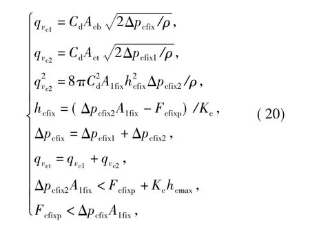
where qvc1and qvc2are the flow rate through the bleeding orifices and compressive valve bores in compressing process,Δpcfix1and Δpcfix2the pressure differences between both ends of compressive bores and both sides of the compressive valve disk in the fixed valve,hcfixthe open height of the compressive valve disk,hcmaxthe max open height of the compressive valve disk,Actthe total area of the compressive valve’s bores in the fixed valve and Kcthe preload spring’s stiffness of the compressive valve in the fixed valve.
When the wheel beat is still small,the beat speed is high enough and the valve opens fully in the compressing process,the oil can not flow through the floating valve.In this case,the damping characteristic can be expressed as

If the wheel beat and the beat speed are quite small in the rebound process,the oil can not flow through the floating valve,thus,only the bleeding orifice of the fixed valve works.In this case,the damping characteristic can be expressed as
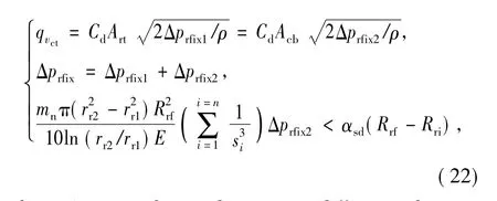
where Δprfixis the total pressure difference between both ends of the fixed valve,Δprfix1and Δprfix2the pressure differences between both ends of the rebound valve bores and the rebound valve disks of the fixed valve,Artthe total area of the rebound valve bores in the fixed valve,rr1and rr2the inner and outer radii of the rebound valve bore in the fixed valve,Rrfthe distance between the centerline of the fixed valve and the centerline of fixed valve bore,Rrithe radius of the gasket in the fixed valve,αsdthe angle of the valve seat and the valve disk in the fixed valve,sithickness of the ith valve disk,mnthe number of rebound valve bores in the fixed valve.
When the wheel beat is still small and the beat speed increases in the rebound process,the oil can not flow through the floating valve.In this case,the damping characteristic can be expressed as
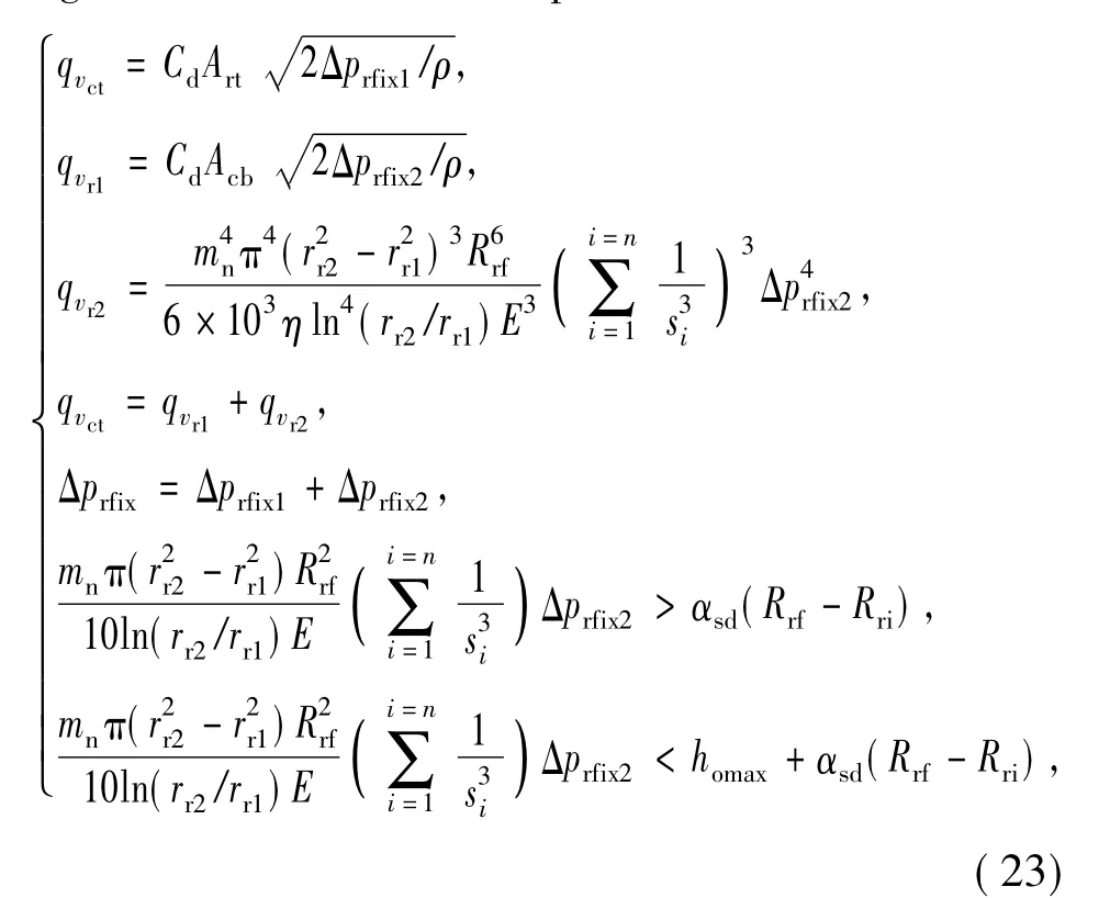
where qvr1and qvr2are the flow rate through the bleeding orifices and the rebound valve bores respectively,homaxthe maximum open height of the rebound valve disk.
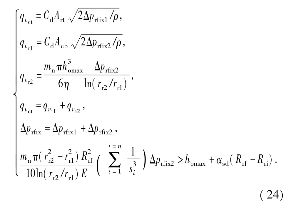
When the wheel beat is still small and the beat speed is high enough and the valve opens fully in the rebound process,the oil can not flow through the floating valve.In this case,the damping characteristic can be expressed as
The external characteristic curves are shown in Fig.4.When the wheel beat is small,the oil can not flow through the floating valve.Only the fixed valve works,so the damping force is small.If the wheel beat is larger,the oil can flow through the floating valve.The damping force produced by the floating valve will be added to the damping force produced by the fixed valve,thus,the damping force is large.The damping force of the floating valve is designed as 50%of the damping force of the fixed valve.

Fig.4 External characteristics of outboard inductive damping valve
3 Comparison of Outboard Inductive Damping Valve and Common Damping Valve
We take a new-type domestic off-road vehicle as an example.The effects of the outboard inductive valve and the common outboard valve on the vehicle comfort and ground adhesion are analyzed by using a 1/4 suspension dynamic model.The main parameters of the original suspension system with common valve are listed in Table.1.For comparison,the transition speed of the outboard inductive valve is the same with that of the common valve.The damping force of the common valve is about 120%of that of the fixed valve in the outboard inductive valve.
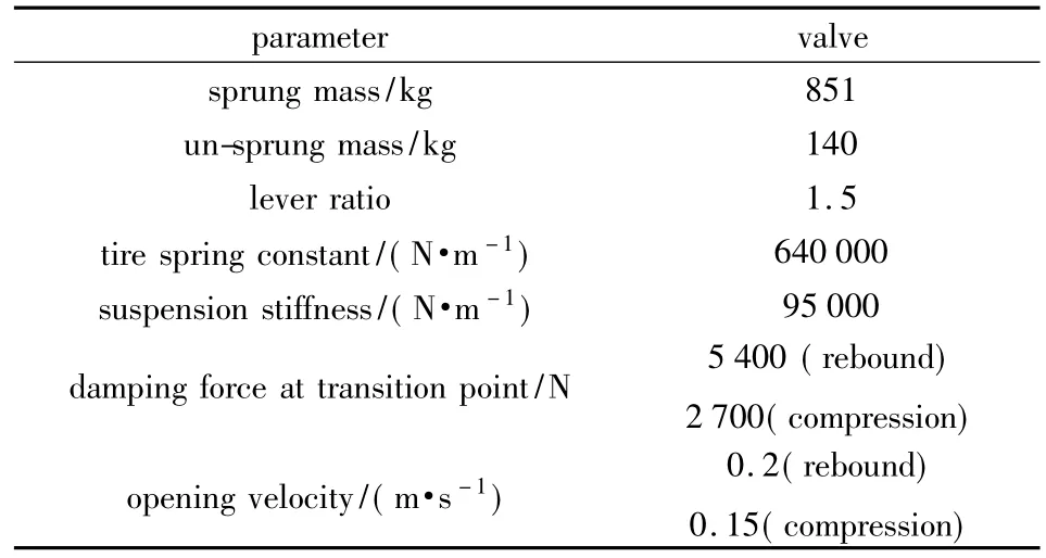
Table 1 Parameters of a suspension system
The travel zone of the floating valve is set as±15 mm.The RMS of sprung mass acceleration and tire load of the vehicle equipped with the outboard inductive valve and the common outboard valve in grade D,E and F road are shown in Fig.5 to Fig.10.When the speed of the vehicle is low,The RMS of sprung mass acceleration of the suspension equipped with the outboard inductive valve is lower than that of the suspension equipped with the common outboard valve.With the increase of the velocity,the stroke of suspension increases and the probability that the outboard inductive valve enters into hard mode increases also,so the sprung mass acceleration RMS of the suspension with the outboard inductive valve increases more than that of the common valve.When the vehicle speed is low,RMS of tire load of the suspension with the inductive valve is similar to that of the common valve.With the increase of the vehicle speed,the probability that the outboard inductive valve enters into hard mode increases gradually.Thus,the tire load RMS of the suspension the inductive valve is lower than that of the common valve.Therefore,the outboard inductive valve can improve the ride comfort at low speed,while it can improve the ground adherent at high speed.
4 Test of Outboard Inductive Damping Valve’s External Characteristics
The mathematical model and adjustment logic of the inductive valve can be verified by using bench test.The bench test and data processing method are based on an automobile standard—QC/T545-_1999.The external characteristics of the damping valve are measured in a test bench,as shown in Fig.11.
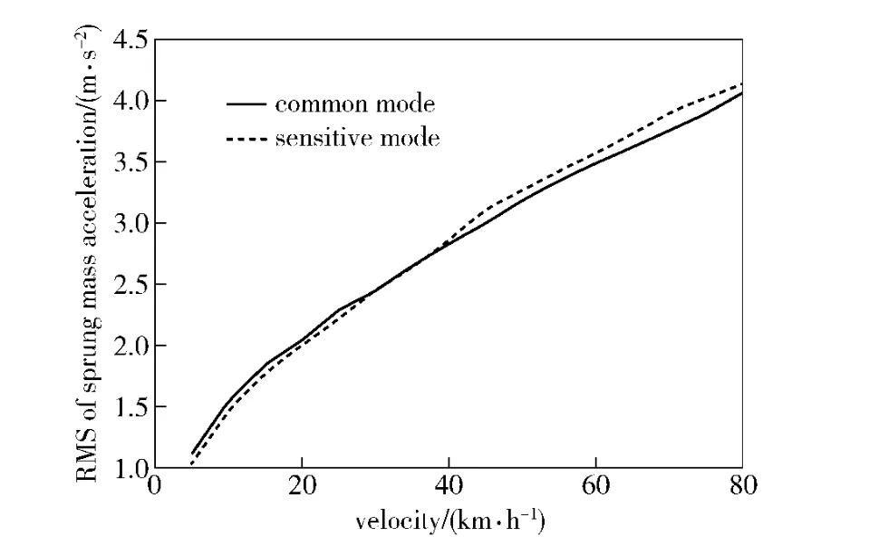
Fig.5 Sprung mass acceleration vs.vehicle velocity(in grade D road)

Fig.6 Dynamic wheel force vs.vehicle velocity(in grade D road)
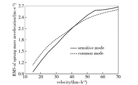
Fig.7 Sprung mass acceleration vs.vehicle velocity(in grade E road)
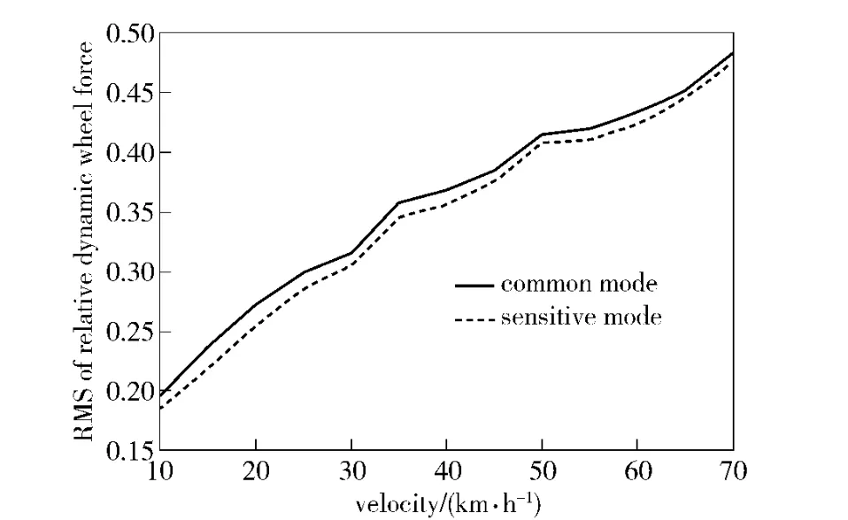
Fig.8 Dynamic wheel force vs.vehicle velocity(in grade E road)

Fig.9 Sprung mass acceleration vs.vehicle velocity(in grade F road)

Fig.10 Dynamic wheel force vs.vehicle velocity(in grade F road)
The installation is shown in Fig.11.The input excitation signals are a sine signal with 40 mm in amplitude and 1 Hz in frequency and a sine signal with 30 mm in amplitude and 2 Hz in frequency.The results are shown in Fig.12 and Fig.13,respectively.The damping forces are positive in rebound process and negative in compressing process.
The damping stage is changed at-15 mm in rebound process and+15 mm in compressing process,as shown in Fig.12 and Fig.13.It shows that the designed adjustment logic is very proper and the outboard

Fig.11 Test bench

Fig.12 Damping force vs.displacement(1 Hz±40 mm)
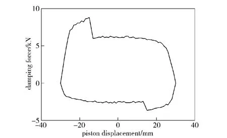
Fig.13 Damping force vs.displacement(2 Hz±30 mm)
inductive valve can be adjusted according to the input amplitude.
The calculated and tested results of damping force are shown in Fig.14.The maximum difference is only 8.3%.It shows that the mathematical model of the valve is quite accurate and the developed outboard inductive damping valve without any electronic control can automatically adjust the damping.

Fig.14 Comparison of simulation and test results
5 Conclusions
A novel outboard inductive damping valve is designed for a hydro-pneumatic suspension,in which the damping coefficient can be adjusted without any electronic control.Its mathematical model is proposed.The comfort and tire load characteristics of the inductive damping valve and common damping valve are compared in grade D,E and F roads.The external characteristic of the inductive valve is verified by bench test.The results show that the mathematical model of the valve is quite accurate and the developed valve can improve the ride comfort at low vehicle speed and ground adherent at high vehicle speed,then it can improve the speed of the off-road vehicle.Therefore,this outboard inductive damping valve is suitable for applications in high speed off-road vehicles.
[1]YU De-fu.Design study of smoothness-to-safety ratio in suspension shock absorber outer characteristic[J].Vehicle and Power Technology,2002,(3):30 -32.
[2]John C D.The shock absorber handbook[M].USA:Society of Automotive Engineers,Inc,1999.
[3]Duym S W.Simulation tools,modeling and identification,for an automotive shock absorber in the context of vehicle dynamics[J].Vehicle System Dynamics,2000,33:261-283.
[4]LANG H H.A study of the characteristics of automotive hydraulic dampings at high stroking frequencies[D].USA:The University of Michigan,1977.
[5]Segel L,LANG H H.The mechanics of automotive hydraulic dampings at at high stroking frequencies[J].Vehicle System Dynamics,1981,10:82 -85.
- Defence Technology的其它文章
- Cooperative Navigation for Autonomous Underwater Vehicles Based on Estimation of Motion Radius Vectors
- Fuzzy Jamming Pattern Recognition Based on Statistic Parameters of Signal’s PSD
- Study on Instable Combustion of Solid Rocket Motor with Finocyl Grain
- A GNSS Signal Blind-decoding Algorithm at Low SNR
- Study of Load Modeling Technology on Hardware-in-the-Loop Simulator of Gun Servo System
- Stability of Composite Braking Produced by Retarder and Braking System