
Compact Pneumatic Pulse-Jet Pump with Venturi-Like Reverse Flow Diverter
2011-03-22 10:08XUCong徐聪LIUBinbin刘斌斌andJINGShan景山11InstituteofNuclearandNewEnergyTechnologyTsinghuaUniversityBeijing100084ChinaChinaNuclearPowerEngineeringCoLtdBeijing100840China
关键词:景山
XU Cong (徐聪)*, LIU Binbin (刘斌斌) and JING Shan (景山)11 Institute of Nuclear and New Energy Technology, Tsinghua University, Beijing 100084, China China Nuclear Power Engineering Co. Ltd, Beijing 100840, China
1 INTRODUCTION
The chemical, metallurgical, and energy industries are involved with the storage and subsequent processing of considerable amounts of fluids that are corrosive, toxic, radioactive, or simply at high temperature.These hazardous fluids pose at least two problems.First, their dangers may result in significant harm to short-range operators. Second, harsh work environments accelerate the damage to equipment, especially its moving parts, so maintenance and replacement are often required. For example, the mechanical bearings and impellers in centrifugal pumps [1-3] that are widely used for industrial production can quickly become inoperative due to metallic corrosion. One of the most common operations that often results in the above two problems involves lifting and transporting a hazardous fluid from a storage tank. Therefore, identifying the pumps available for hazardous environments is critical to overcoming these problems.
One example of maintenance-free pumps for hazardous fluids that are presently being researched extensively is the pneumatic pulse-jet pump with a reverse flow diverter (RFD) [4-6]. The Venturi-like RFD without moving parts offers a simple structure as well as the advantages of stability and durability. It will not heat or dilute the liquid and can transport a high-temperature liquid that is close to its boiling point or a radioactive liquid that contains suspended solid. In an operating cycle of the pneumatic pulse-jet pump, the switch between the suction and output discharge operations can be realized conveniently by using solenoid valves under remote control. Thus, the pneumatic pulse-jet pump can be used safely in harsh environments.
Early research on the pneumatic pulse-jet pump with an RFD as the core of equipment was mainly performed in the United Kingdom. From 1967 to 1972,Walkden successfully used a pump with an RFD to transport a potassium salt at 1,500 °F within the central laboratory of the British General Electric Company [7]. Since then, Tippettset al. [8, 9] researched widely pumping cycle control, single-acting RFD pumps, and 2-RFD pumps, as well as double-acting pumps with two displacement vessels and one flow junction (FJ). In the 1980s, British Nuclear Fuels Limited (BNFL) conducted successful research on a pump system with an RFD for application in a nuclear fuel reprocessing plant [10]. In a Springfield industryscale experiment, the maximum lift of a pump system with an RFD was 30 m while the flux was 20 m3·h-1.In the 1980s and 1990s, US researchers began to study the application of RFDs in Oak, Idaho, and other radioactive waste disposal areas. Smith and Counce studied the performance characteristics of plane wall reverse flow diverters [11] and axisymmetric reverse flow diverters [12], and proposed a prediction model of RFD performance. In the US, Mark successfully used the pneumatic pulse-jet pump to transport slurry [13]. Gaoet al. [14] developed an energy loss pressure ratio formulation of the main flowing unit of a pulsed liquid jet pump and found that the pulse frequency is the main factor influencing energy and pumping capacity.
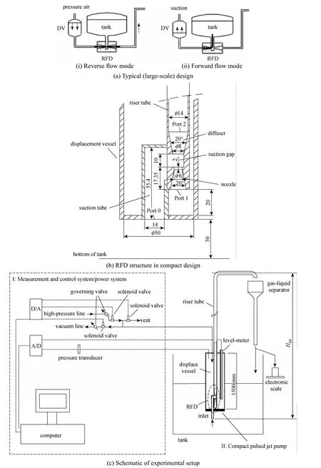
Figure 1 Designs for pneumatic pulse-jet pump with Venturi-like reverse flow diverter
Of the reported works, the majority focused on transportation theory, stable performance, and the effects of geometrical parameters for a large pneumatic pulse-jet pump with one displacement vessel and one separate RFD. However, in practice, the main problem lies in the means of lifting and transporting a hazardous fluid within an extremely small installation space. For example, when radioactive fluid is transported, a narrow mounting hole is necessary to allow installation of the pump into the storage tank and yet prevent radioactive leaks. To pass through the narrow mounting hole,the pneumatic pulse-jet pump must be compact. At present, there remains a scarcity of experimental studies on the structure and performance of compact pneumatic pulse-jet pumps. Indeed, no reports have addressed the effects of liquid viscosity, particle mass concentration,lifting height, and compression pressure on the pumping capacity.
In this study, liquid mixtures and liquid-solid mixtures with different liquid viscosities and particle mass concentrations were prepared using glycerol, water, and quartz sand as raw materials. To provide a basis for engineering and modeling, the effects of liquid viscosity, particle mass concentration, lifting height,and compression pressure on both pumping performance and operating rules have been experimentally investigated.
2 EXPERIMENTAL
2.1 Compact design
As shown in Fig. 1 (a), the main structure of a conventional pneumatic pulse-jet pump is composed of a displacement vessel (DV) and an RFD that runs in two modes. The reverse flow mode is for lifting and transporting fluid, whereas the forward flow mode is for filling the DV with fluid from a storage tank. The most significant feature of this conventional design is the separation of the RFD and the DV, which are connected by pipelines. For lower resistance in the forward flow mode, RFDs are often arranged horizontally.When conditions are steady, the pumping capacity of a pneumatic pulse-jet pump is proportional to the volume of the DV and the area of the nozzle. The advantage of this structure is that the sizes of DV and RFD can be determined by the required capacity, not by the compatibility of RFD size with DV. This type of design is aimed at large pumping capacities and largescale applications.
In this paper, a compact pump is designed. To address the restriction of a narrow installation space,the RFD is arranged vertically inside the DV of 50 mm diameter, as illustrated by Figs. 1 (b) and 1 (c).With the compact design, the entire device can be fixed in the hazardous fluid tank through the narrow mounting hole without the need of significant restructure of the tank. Since the component sizes and assembly mode of the DV and RFD in the compact design are different from those in the conventional design, the flow resistance varies from one RFD pumping system to another. Accordingly, the pressure variation in the DV of the compact design, which forces transport of the fluid against the flow resistance, is different from that in the conventional design when in the reverse flow mode. Furthermore, the limitation on the pumping performance may also differ, since these two kinds of RFD pumping system differ in the maximum jet velocity at the nozzle exit and in the balance of the drive force with the flow resistance.
In this study, the RFD structure is composed of a nozzle and diffuser, as shown in Fig. 1 (b). The nozzle and diffuser have the same 20° angle of convergence or divergence. The nozzle has an outlet diameter measuring 6 mm, and the diffuser has an inlet diameter measuring 8 mm. The space that separates the nozzle and diffuser, which is known as the suction gap, is 10 mm long and 14 mm wide. The riser tube positioned after the diffuser measures 14 mm in diameter.
The experimental procedure for the compact pulse-jet pump in this study is outlined in Fig. 1 (c).The equipment includes a pressure/vacuum generator,compact pulse-jet pump, and measurement/control system. The pressure generator delivers compressed air that propels the fluid along the riser tube toward higher elevation. The vacuum generator draws the fluid into the DV. At the top of the DV, a sensor reports the pressure corresponding to that fixed measurement point. The position of the fluid surface in the DV is monitored by a level gauge in the measurement/control system. According to the quantity of fluid obtained from the riser tube outlet, the pumping capacity may be calculated. The operating conditions of this experiment are presented in Table 1.
2.2 Working procedure
Similar to that of the conventional design, the working process of the compact pulse-jet pump includes a suction process and a compression process, as indicated by Fig. 2.
Suction process [Fig. 2(a)]: the compressionsolenoid valve and vent-solenoid valve both close and the vacuum-solenoid valve opens, so the vacuum pump can work. Therefore, air in the DV is evacuated,and consequently, liquid in the tank is drawn into the DV along Port 0 to Port 1. The flow in the RFD under the suction process is known as the forward flow mode of the RFD.
Compression phase [Fig. 2(b)]: the suctionsolenoid valve and vent-solenoid valve both close and the compression-solenoid valve of the pressure generator opens. Compressed gas works on the fluid in the DV, compelling it emanates from the nozzle outlet(Port 1) to form a jet across the suction gap. It is notedthat under the influence of the inertia, the jet tends to flow from Port 1 to Port 2, rather than along the direction from Port 1 to Port 0, as long as the jet velocity is enough high. The intense jet flow from Port 1 to Port 2 will produced a low-pressure area surrounding its core. Consequently, part of the fluid in the tank are induced through Port 0 into the suction gap, termed it jet entrainment. The induced fluid mixes with the jet,exchanges momentum and mass, and then enters the diffuser. Part of kinetic energy is converted to static pressure energy inside the diffuser with an increasing flow area, lifting the mixed fluid to a high elevation through the riser tube. The jet entrainment is expected because flux in Port 2 is greater than that in Port 1.However, when the riser tube positioned after the diffuser exhibits excessive resistance, the jet entrainment will be broken attributed the weak jet flow. Subsequently, part of the jet flow in the suction gap will flow from Port 1 to Port 0, and return to the tank,termed it back-flow. The fluid flowing in RFD under the compression process gives the reverse flow mode its name. In addition, during the compression process,when the level of fluid in the DV drops to a predefined low, the compression-solenoid valve will close and the vent-solenoid valve will open, so compressed air in the DV will be exhausted immediately. Under the influence of the gravity, the fluid filled in the riser tube will fall down and emanate from the diffuser entrance. One part of the falling fluid flow into the DV through Port 1, while another return to the tank through Port 0. Specially, as the velocity of falling fluid at the diffuser entrance is enough high, a jet may be created in the suction gap. The jet may induce the fluid in the tank through Port 1 into the DV, which reduces the time required for filling up the DV during the following suction process. When the pressure in the vessel is reduced to a certain value, the ventsolenoid valve will close and the vacuum-solenoid valve will open. Hence, the suction process will restart and the cycle will be repeated.

Table 1 Operating conditions of experiment
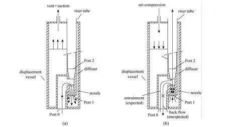
Figure 2 Working processes of compact pulse-jet pump: (a) forward flow mode, and (b) reverse flow mode
2.3 Simulation fluids and measuring instruments
In this study, two types of mixtures are prepared as the working fluids: liquid mixture and liquid-solid mixture. The former is glycerin-water solution to simulate other liquids, while the latter is glycerin-water-quartz sand mixture to simulate slurries.The proportion of glycerin is varied to adjust the viscosity of each mixture. Additionally, a paddle-type stirrer is utilized to ensure a homogeneous state of the mixtures, whose properties are listed in Table 2.
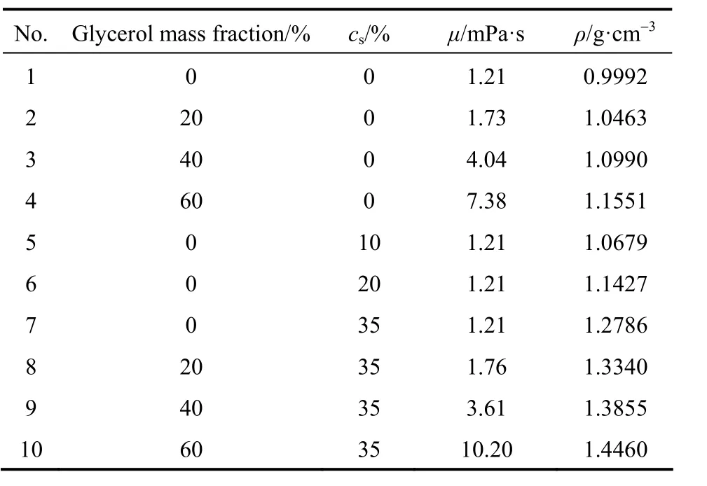
Table 2 Viscosities, densities, and mass fractions of different fluid mixtures
Specifically, the properties of the materials used in this work are as follows:
Glycerin: purity, 99.9%; melting point, 18.17 °C;relative density, 1.261 g·cm-3at 25 °C; absolute viscosity, 9.54 Pa⋅s.
Quartz sand: SiO2content, 90%-99%; relative density, 2.65 g·cm-3at 25 °C; average particle size,52.45 μm.
The measuring instruments used are as follows:
a) Digital rotational viscometer: DV-1, Fungilab S.A., Spain.
b) Densitometer: Den Di-1, Beijing Electrical Equipment Co. Ltd., China.
c) Particle size analyzer: Mastersizer 2000, Malvern Instruments Ltd., UK.
3 RESULTS AND DISCUSSION
3.1 Pressure signal analysis
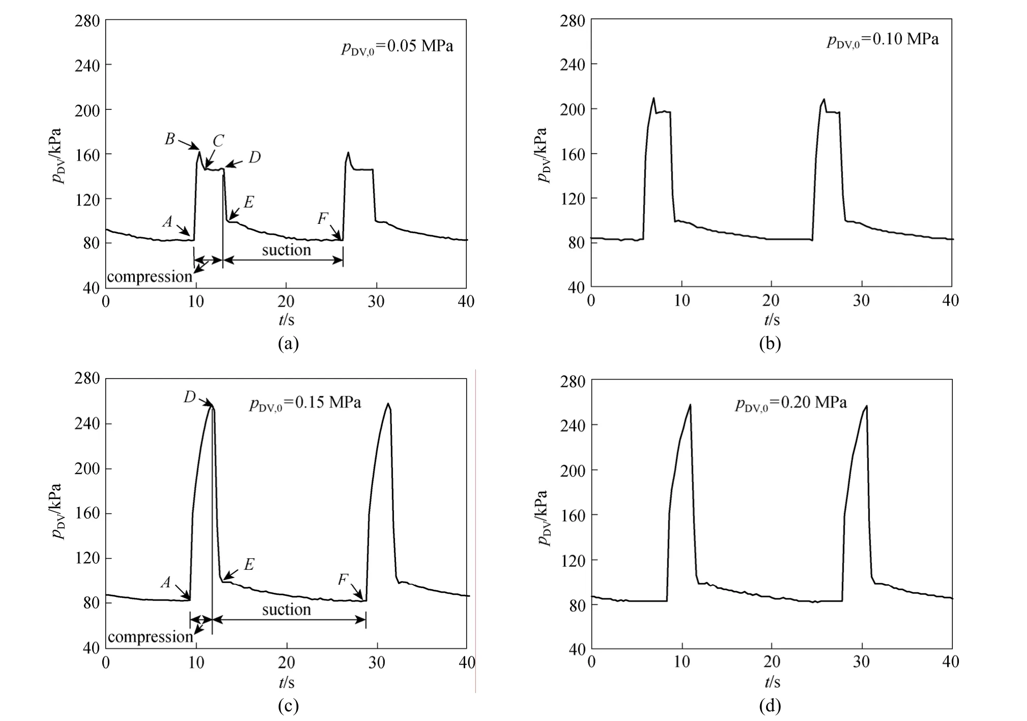
Figure 3 Pressure signals for different static compression pressures
Once the compression valve opens, compressed air passes through the gas pipe and acts on liquid in the DV. Liquid then emanates from the RFD nozzle exit, forming a jet across the suction gap. When the compression valve is closed, the pressure of the compressed gas in the pipe,pDV,0, is known as the static compression pressure (gauge pressure). The real-time pressure in the DV,pDV, is measured using the pressure data acquisition system. Fig. 3 shows that the DV pressure signal is divided into two steps by the operation of the pneumatic pulse-jet pump with lifting height 6.74 m and initial liquid level in the DV,HDV,0=125 cm, as mixture No 1 listed in Table 1 was adopted. These steps represent the compression process [A-Din Figs. 3 (a) and 3 (c)] and the suction process [D-Fin Figs. 3 (a) and 3 (c)]. Fig. 3 also clearly shows that for different static compression pressures the DV pressure signal of the compression step can exhibit two different modes.
The first mode is the “plateau” mode [Figs. 3 (a)and (b)]. In this mode, the pressure peak exists at the beginning of the compression step, and approximately the constant pressure region comes afterwards. The reason for this phenomenon is that if low-pressure gas enters the DV, its expansion work cannot entirely overcome the interlaminar shear force (including wall friction) of the transported liquid, so liquid in the DV flows less and gas pressure increases steeply.Conversely, at PointBthe expansion work of the high-pressure gas can overcome the liquid flow resistance, so liquid flow in the DV is accelerated and gas pressure there is reduced, thus a pressure peak results.As transported liquid is discharged from the riser tube outlet, the liquid flow resistance is constant and in balance with the compressed gas expansion work, so the liquid acceleration process stops. The rate of liquid level drop in the DV is similarly constant, as highpressure gas in the DV continues to push liquid out by constant expansion. Because the air supply rate balances the gas expansion rate, a constant region exists in the pressure signal.
The second mode is a “knife” mode [Figs. 3 (c)and 3 (d)]. In terms of the change in pressure signal,the most noticeable feature is the absence of a constant pressure region during the compression step[sectionB-Din Fig. 3 (a) is simplified to a smooth curveA-D]. In this mode, during the compression step the high-pressure gas accelerates expansion in the DV,so the liquid level there decreases rapidly. The expansion work of this high-pressure gas is sufficient to overcome the interlaminar shear force of liquid flow,including the wall friction. The result is that in this initial step the liquid level in the DV begins to rapidly decrease. Thus, no pressure peak exists in this mode.At the same time, the ample gas supply due to a higher pressure means that the expansion work of the compressed gas is always greater than resistance loss of the liquid flow, even if liquid is discharged from the riser tube outlet. Moreover, the liquid level in the DV rapidly decreases, while the rate of pressure signal change gradually decreases because the expansion rate of the compressed gas increases (i.e., the pressure signal slope in Fig. 3 (c) gradually decreases). However,pDVexhibits an upward trend until PointD, where the DV begins to empty and suction commences.
The reasons for the differences between the two modes are important and can be explained as follows:In the steady pressure region of the plateau mode, liquid in the DV is exhausted with a nearly constant rate.Thus, the jet flow that forms at the RFD nozzle exit is considered a quasi-stable jet, so the stable jet equations can be used for theoretical analysis. In the knife mode, however, the unstable jet equations are used at the RFD nozzle exit during the entire compression process. Additionally, in the operation of a conventional pneumatic pulse-jet pump, the greater pumping capacity attributed to a greater DV volume also results in a greater flow resistance (including gravity work)that the compressed gas needs to overcome. The expansion work of compressed gas then balances more easily with the energy lost to flow resistance. Therefore, the plateau mode appears fundamental to the operation of a conventional pneumatic pulse-jet pump,whereas the knife mode really does not.
3.2 Pumping performance for liquid mixture
Liquid viscosity, compression pressure, and lifting height are three factors in the pumping performance of a compact pump and these are investigated experimentally. To characterize the pumping performance,the following dimensionless parameters are defined:
whereqis the suction factor,Euis the Euler number ratio, andηis the effective lifting factor. More explicitly,qis the ratio of the flux sum at Port 2 to that at Port 1 for a single pumping cycle, including suction and compression. Whenq>1, the expected entrainment phenomenon occurs in the suction gap during the compression process (RFD in the reverse flow mode). Whenq<1, the back-flow phenomenon occurs.The smaller the value ofq, the more serious the back-flow phenomenon and the smaller the pumping capacity. The suction factor q may be used to estimate the RFD pumping performance with the riser tube volume taken into account.is the ratio between the Euler number at the riser tube outlet and that at the fluid level of the DV, representing the loss of liquid momentum between the DV level and the riser tube outlet.ηis the ratio between the flux at the riser tube outlet and that discharged from the DV, representing the effective capacity of the compact pulse-jet pump during one cycle. The liquid within the riser tube is not considered in the effective lifting factorηas that is not transported beyond the riser tube outlet.
3.2.1Effects of compression pressure and liquid viscosity
Figure 4 shows the effect of static compression pressure on the pumping performance of the compact pulse-jet pump for mixture Nos. 1-4 (see Table 2)where lifting heightHliftis 2.78 m and initial liquid level in DVHDV,0is 125 cm. In particular, Fig. 4 (a)demonstrates that pumping capacity increases with static compression pressure. However, when the compression increases to a certain pressure, the capacity of the compact pulse-jet pump reaches a limit. If the pressure increase continues, the pumping capacity may actually decrease. Fig. 4 (b) demonstrates that the suction ratioqincreases with compression pressure to some extent but also eventually reaches a limit. Based upon the above results, a reasonable conclusion is that the pumping performance of the RFD in reverse flow mode is controlled by jet inertia and flow resistance along the riser tube. Since the jet inertia dominates the flow resistance as compression pressure is lower,more liquid enters the diffuser and is lifted with compression pressure increasing. When the compression pressure (i.e., jet speed) increases to a certain value,the flow resistance begins to increase as the square of the liquid speed and the effect of secondary flow resistance exceeds that of jet inertia, so the pumping capacity begins to decrease. In contrast with the compact pump, the conventional pneumatic pulse-jet pump has a diffuser and riser tube of greater diameter and thus suffers less effect from flow resistance. Hence, the reason that pumping capacity reaches a limit and eventually becomes reduced is that cavitation occurs due to the excessive jet speed at the nozzle exit [15].
Figure 4 (a) also shows the effect of liquid viscosity on the pumping performance of the compact pulse-jet pump. Specifically, the pumping capacity decreases as the mixture viscosity increases. A greater liquid viscosity naturally causes more liquid resistance throughout the entire flow process and the effect of the flow resistance along the riser tube becomes more evident. Thus, more liquid returns to the storage tank,flowing from Port 1 to Port 0. However, the compact pulse-jet pump reaches a capacity of 170.7 L·h-1for a mixture with a high viscosity of 7.38 mPa·s. In other words, the RFD has an excellent capacity for lifting and transporting such high-viscosity mixtures.

Figure 4 Effects of compression pressure and liquid viscosity on pumping performanceμ/mPa·s: □ 1.21; ○ 1.73; △ 4.04; ▽ 7.38
3.2.2Effect of lifting height

Figure 5 Pumping capacity and effective lifting factor for two heightsLifting height/m: □, ☆ 2.78; ■, ★ 6.74
Figure 5 shows the experimental results for pumping capacity and effective lifting factor with mixture No. 1 (see Table 2), initial liquid level of 125 cm, and a lifting height of either 2.78 m or 6.74 m. Evidently,the pumping capacity and effective lifting factor both decrease considerably as the lifting height increases.This further emphasizes that the effect of flow resistance on the RFD pumping performance is significant.Fig. 5 indicates that with a lifting height of 6.74 m the RFD pumping capacity eventually reaches 89.6 L·h-1.
3.2.3Non-dimensional performance curve
If the viscosity of a mixture is fixed, the main influencing parameters are the compression pressure,the lifting height, and the initial level of liquid in the DV. Fig. 6 shows that the effective lifting factor can be described as a unique non-dimensional function of the Euler number ratio as follows:

In a practical application of a compact pneumatic pulse-jet pump, the pressures at the riser tube outlet is the known ambient pressure, whileUoutandηare typically determined according to practical requirements. Substitution ofUoutandηin Eqs. (3) and (4)means thatpDVcan then be determined for a specific viscosity and lifting height. Therefore, within a certain range, the non-dimensional performance curve ofηprovides a way to select or confirm the operating parameters of a compact pneumatic pulse-jet pump.
3.3 Pumping performance for liquid-solid mixture
This experiment investigated the effects of liquid viscosity, particle mass concentration, and compression pressure on the performance of the compact pneumatic pulse-jet pump for liquid-solid mixtures and a lifting height of 6.74 m.
3.3.1Effects of compression pressure and particle mass concentration
Figure 6 Dimensionless performance Euout/Eu0 versus effective lifting factor η (glycerin-water solution, lifting height 2.78-6.74 m, initial liquid level in the DV 84-127 cm, static pressure 0.05-0.20 MPa, and liquid viscosity 1.21-7.38 mPa·s)
Table 3 Effect of compression pressure on pumping capacity
Table 3 shows the effect of static compression pressure on the pumping performance for mixture Nos.5 and 7 (see Table 2) with particle mass concentrations of 10% and 35%, respectively. The pumping capacity for liquid-solid mixtures increases with static compression pressure. However, the pumping capacity atpDV,0=0.15 MPa evidently decreases as the particle mass concentration increases. Further, the decline of pumping capacity in No. 7 system with 35% particle mass concentration is not significant compared with No. 1 system (seen Fig. 5, liquid system) or No. 5 system with 10% particle mass concentration whenpDV,0=0.20 MPa. This indicates that the resistance created by particle mass concentration is overcome to a certain extent when the compression pressure (or jet speed) is raised.
During the lifting process, an important evaluation indicator is the degree of liquid-solid separation.Therefore, while in the reverse flow mode, liquid-solid samples were gathered at the riser tube outlet and storage tank to determine the particle mass concentration by filtration. Further, the particle size distributions were measured using a laser particle size analyzer. Fig. 7 shows the particle size distribution errorEdthat is calculated as the difference between the integrated areas of distribution curves. Regardless of the compression pressure, the particle size distribution was in good agreement with that of the original mixture and thus indicated no separation phenomenon.
Table 4 shows that the differences in particle mass concentration for different compression pressures were insignificant, especially at high particle mass concentration. Since fluid is drawn into the DV at Port 0 on the bottom plate of the compact pump, the area surrounding Port 0 is less affected by the stirring paddles and undergoes a less uniform liquid-solid mixing. This may explain why the particle mass concentration is slightly higher at the riser tube outlet than at the tank, andEdis also slightly higher for 10% solid concentration than others. These results indicate that for liquid-solid mixtures the performance of the compact pneumatic pulse-jet pump is satisfactory.
3.3.2Effect of viscosity
Figure 8 shows the effect of liquid viscosity on the pumping performance for mixture Nos. 7-10 (see Table 2) with a static compression pressure of 0.20 MPa and a lifting height of 6.74 m. The results are similar to those for pure liquid [see Fig. 4 (a)].
Figure 7 Particle size distributions at riser tube outlet and in storage tank for different original particle mass concentrationsin tank; in riser tube outlet
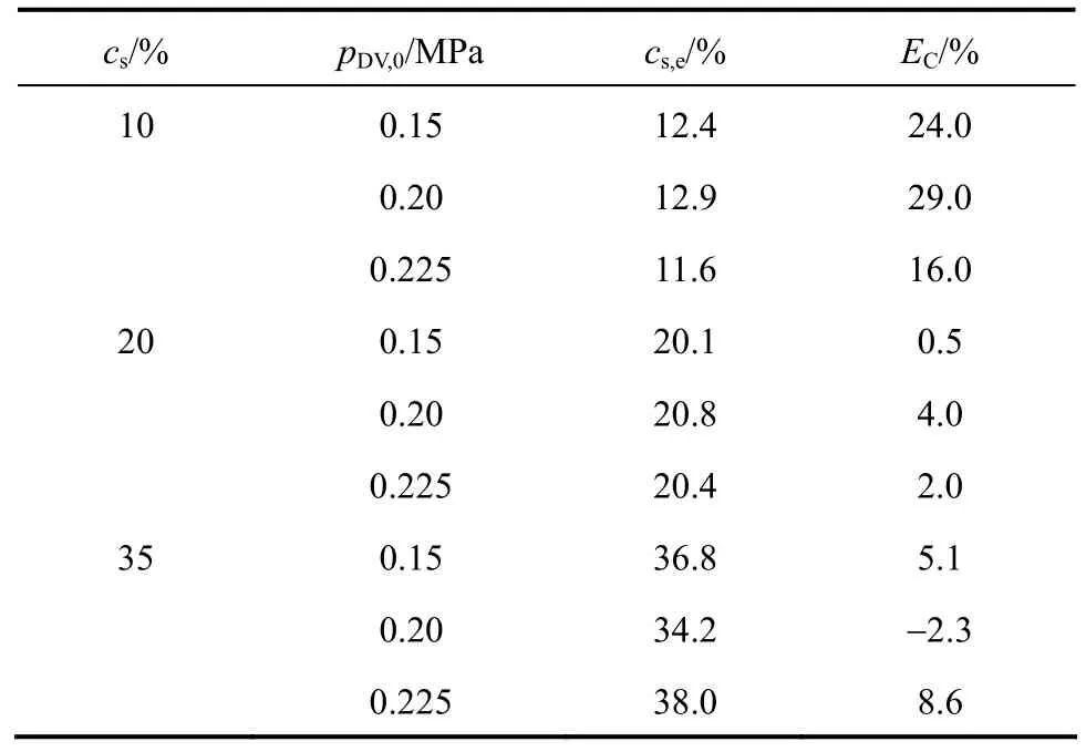
Table 4 Particle mass concentration for different compression pressures
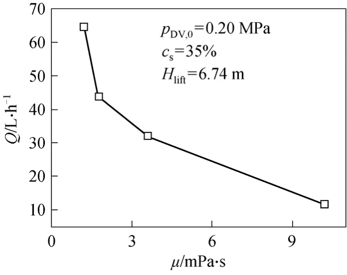
Figure 8 Effect of viscosity on pumping capacity for liquidsolid mixture
Figure 9 shows the analytical features of particle size for samples taken at the riser tube outlet and in the storage tank for mixtures with different viscosities.The particle size distributions coincide well, since the maximum value of the particle size distribution errorEdis only 3.20%. This indicates that no liquid-solid separation phenomenon occurred with a particle mass concentration of 35% and a liquid viscosity of 7.28 mPa·s.
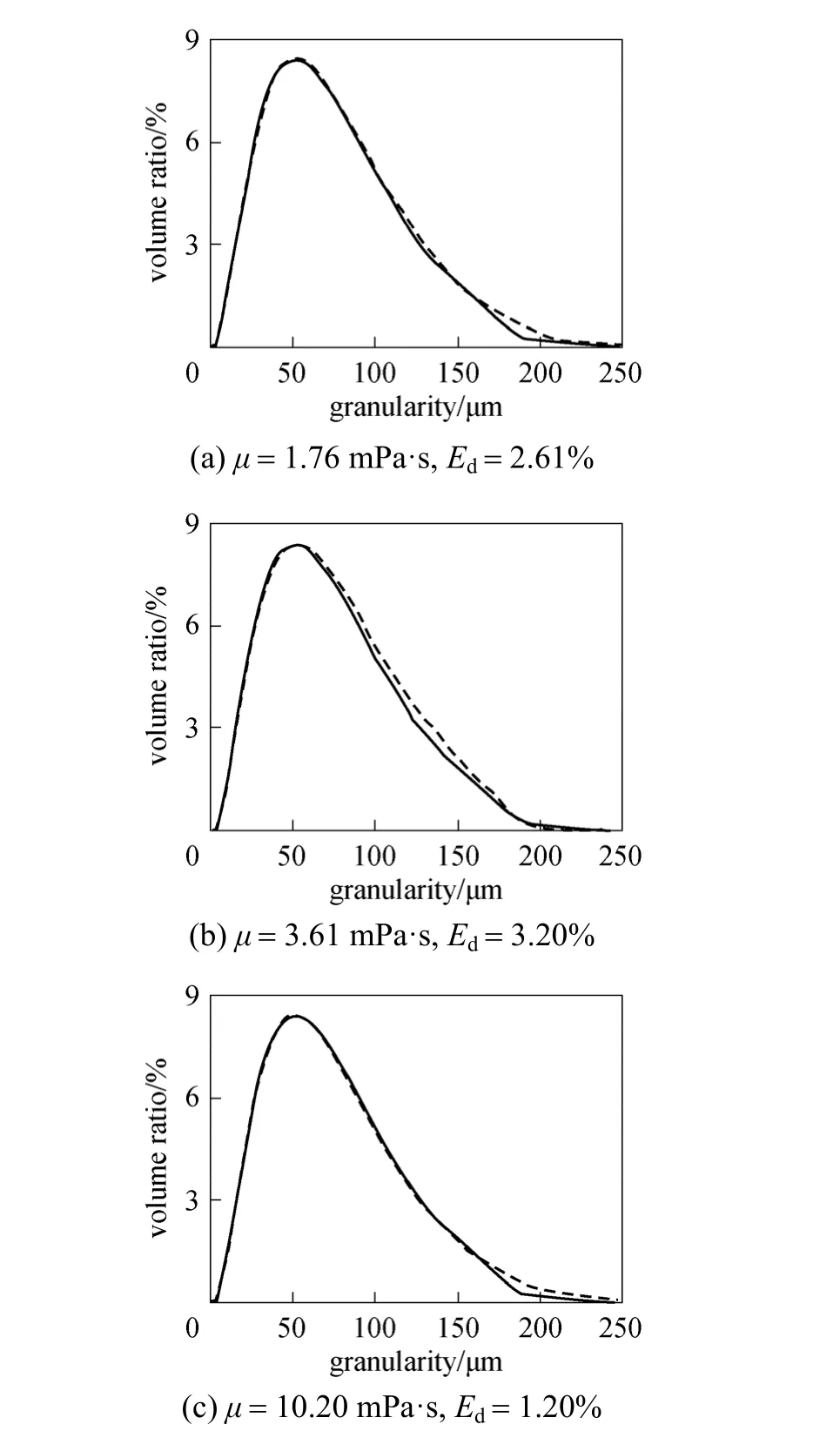
Figure 9 Particle size distributions at riser tube outlet and in storage tank for different mixture viscositiesin tank; in riser tube outlet
4 CONCLUSIONS
The experimental results demonstrate that for both liquid and liquid-solid mixture the performance of the compact pneumatic pulse-jet pump is superior.The following are specific conclusions drawn from the experiments:
(1) Pumping performance is mainly controlled by jet inertia and flow resistance along the riser tube located after the RFD diffuser. When static compression pressure increases, jet inertia at the RFD nozzle is enhanced and pumping capacity increases. As the liquid viscosity increases, the flow resistance increases and the pumping capacity decreases. The compact pulse-jet pump reaches a pumping capacity of 170.7 L·h-1for a mixture with a high viscosity of 7.38 mPa·s. This indicates that the RFD has a reliable pumping capacity even for high-viscosity liquids.
(2) Pumping capacity and effective lifting factor are evidently reduced when lifting height increases.The capacity of the compact pulse-jet pump reaches 89.6 L·h-1with a lifting height of 6.74 m.
(3) The Euler number ratio and effective lifting factor describe a non-dimensional performance curve that depends on the compression pressure, the lifting height, and the initial level of liquid in the DV, when the liquid viscosity is fixed. This provides a way to select or confirm the operating parameters of a compact pneumatic pulse-jet pump.
(4) Particle size distributions were in excellent agreement with those of the original mixtures for different compression pressures and liquid viscosities,exhibiting no separation phenomenon during the pumping experiment. This indicates that for a liquid-solid mixture, the pumping performance of the compact pneumatic pulse-jet pump is well.
NOMENCLATURE
csmass concentration of particles in tank, %
cs,emass concentration of particles in sample from riser tube outlet, %dDVdisplacement vessel diameter, mm
doutriser tube outlet diameter, mm
d0RFD nozzle exit diameter, mm
ECerror in particle mass concentration [=(cs,e-cs)/cs×100], %
Ederror in particle size distribution, %
EuDVEuler number at gas-liquid interface of DV
EuoutEuler number at riser tube outlet
HDV,0initial liquid level in DV, cm
Hliftlifting height, m
pDVpressure of compression gas in DV, kPapDV,0static compression pressure, MPa
poutpressure at riser tube outlet, Pa
Qpumping capacity, L·h-1
qsuction factor
trcompression time, s
UDVfluid descent speed in DV, m·s-1
Uoutfluid speed at riser tube outlet, m·s-1
U0fluid speed at RFD nozzle exit, m·s-1
VDVinitial fluid volume in DV, m3
Vpiperiser tube volume, m3
Woutfluid quality at riser tube outlet in one pumping cycle, kgηeffective lifting factor
μliquid viscosity, mPa·s
ρliquid density, g·cm-3
1 Zhu, Z.C., Chen, Y., Jin, Q.M., Huang, D.H., “Study on high-speed centrifugal-regenerative pump with an inducer”,Chin.J.Chem.Eng.,10 (2), 137-141 (2002).
2 Cui, B.L., Zhu, Z.C., Zhang, J.C., Wu, Y., Chen, Y., “Improving suction performance of centrifugal pumps by using jetting device”,Chin.J.Chem.Eng., 12 (5), 628-632 (2004).
3 Zhu, Z.C., Xie, P., Ou, G.F., Cui, B.L., Li, Y., “Design and experimental analyses of small-flow high-head centrifugal-vortex pump for gas-liquid two-phase mixture”,Chin.J.Chem.Eng., 16 (4), 528-534(2008).
4 Morgan, J.G., Holland, W.D., Pulsatile Fluidic Pump Demonstration and Predictive Model Application, ORNL, Oak Ridge (1986).
5 Smith, G.V., Lewis, B.E., Design of a Pulsed Mode Fluid Pump Using a Venturi Like Reverse Flow Diverter, ORNL, Oak Ridge(1987).
6 Fan, Y.F., Xu, C., Jing, S., “Experimental study on fundamental performance of reverse flow diverters”,Chinese Journal of Nuclear Science and Engineering, 28 (3), 280-288 (2008). (in Chinese)
7 Walkden, J., “Pneumatically driven reciprocating-jet pump: Performance of a servo- controlled valve system and of a pump operating with a molten salt at 1500 °F”, In: 1st Symp. on Jet Pumps and Ejectors, Fluid Engineering, BHRA, Bedford (1972).
8 Tippetts, J.R., Priestman, G.H., Thompson, D., “Developments in power fluidics for application in nuclear plant”,J.Dynamic Systems Measur.Control, 103, 342-351 (1981).
9 Tippetts, J.R., “A fluidic pump for use in nuclear fuel reprocessing”,In: Proc. 5th Int. Fluid Power Symp., BHRA, Bedford, Paper C2(1978).
10 Shaw, H.M., Application of Power Fluidics in British Nuclear Reprocessing Plants, BNFL, Sellafield (1995).
11 Counce, R.M., Smith, G.V., “Performance characteristics of plane-wall Venturi-like reverse flow diverters”,Ind.Eng.Chem.ProcessDes.Dev., 23, 295-299 (1984).
12 Smith, G.V., Counce, R.M., “Performance characteristic of axisymmetric Venturi-like reverse flow diverter”,J.Fluid Control, 4, 19-39(1986).
13 Mark, D.M., “Technology deployments for D&D applications”,AEA Technol., 10 (8), 481-486 (1973).
14 Gao, C.C., Wang, L.H., Chen, D.H., “Theoretical study on energy equilibrium of pulsed liquid jet pump”,Journal of North China Institute of Water Conservancy and Hydroelectric Power, 27 (2),50-53 (2006). (in Chinese)
15 Fan, Y.F., “Experimental study on the performance of reverse flow diverters and pneumatic pulsed fluidic pump used in nuclear industry”,Master Thesis, Tsinghua University, Beijing (2008). (in Chinese)
猜你喜欢
黄河之声(2021年16期)2021-12-14
源流(2021年11期)2021-03-25
戏曲研究(2020年1期)2020-09-21
杂文月刊(2019年15期)2019-09-26
杂文月刊(2019年15期)2019-09-26
杂文月刊(2019年16期)2019-09-25
杂文月刊(2018年21期)2019-01-05
杂文月刊(2018年21期)2019-01-05
喜剧世界(2017年18期)2017-09-23
喜剧世界(2016年24期)2017-01-04
 Chinese Journal of Chemical Engineering2011年4期
- Chinese Journal of Chemical Engineering的其它文章
- Synthesis of Methyl Isopropyl Ketone and Diethyl Ketone over Ni-Na/ZrO2-MnO2-ZnO Catalyst*
- Isotherm Equation Study of F Adsorbed from Water Solution by Fe2(SO4)3-modified Granular Activated Alumina*
- Preparation and Dyeing Performance of a Novel Crosslinking Polymeric Dye Containing Flavone Moiety*
- Solubility of Paclitaxel in Mixtures of Dichloromethane and Supercritical Carbon Dioxide*
- The Kinetics for Electrochemical Removal of Ammonia in Coking Wastewater*
- Solvent Recovery from Soybean Oil/Hexane Miscella by PDMS Composite Membrane*