
基于GIS的机场净空障碍物评定研究
2011-05-05 22:55罗成立1蔡良才1黄命辉2洋2刘莉莉2鹏1
罗成立1 蔡良才1 黄命辉2 鲁 洋2 刘莉莉2 李 鹏1
(1.空军工程大学工程学院,西安,710038,中国;2.空防六处工程科,衡阳,421001,中国)
INTRODUCTION
Airfield obstacle free space is the airspace near the airfield along the route of taking off and landing within a certain range, thatis, the airspace need to be on both ends and sides of the runway as the plane takes off to climb,lands to slide and circles for vision.In this region,ground obstacles impeding the navigation and flight cannot exist.T herefore,airfield obstacle free space should be managed and controlled after carrying out the site of airfield or putting into use[1].
There are already some studies on establishing 3-D model of airfield obstacle free space surface.Some models are built by 3DSMAX software.This modeling approach does not contain geographic information data.T here are some limitations in application.Some are built by digital elevation model(DEM)in the grid format,but the grid of the data is calculated through interpolation.It is mainly applied to vast territory and small undulating topography surface simulation,and it is not appropriate for the airfield obstacle free space surface which marks the boundary line and changs largely in slope geometry.So there is also rare related research data at home and abroad at present.
T he traditional method of assessing the airfield obstacle free space is to map out the free space limit surfaces and obstacle location,and then calculate whether the height of obstacles exceeds the limit height under the free space requirements and triangular relationship.Mapping in this way is slow,low accuracy,difficult to update.T hrough the establishment of airfield obstacle free space model,it can determine obstacle permit height in all planar location around the airfield.Processing and analyzing the obstacles data by using geographic information system(GIS)technology can obtain high efficiency,accurate results,and achieve 3-D visualization of airfield obstacle free space.
In order to perform military airfield obstacle free space surface more accurately,manage military airfield obstacles more effectively,and check the location of any surface limit height neatly and quickly,the mathematical model of obstacle limit surfaces is bulit for military airfield obstacle free space and the 3-D model of airfield obstacle free space surface is given.
1 CONSTRUCTION OF MATHEMATICAL MODEL
1.1 Airfield obstacle free space specifications and coordinate establishment
Airfield obstacle free space zone is composed with runway strip,end free space zone and side free space zone.Its composition is shown in Fig.1.
It seems that each level of airfield obstacle free space limit surfaces are symmetrical vertically and horizontally on the basis of an analysis of airfield obstacle free space specifications,as shown in Fig.1.T herefore,it can be described by using a quarter model of airfield obstacle free space specifications,as shown in Fig.2.
In Fig.2,L is the length of runway strip,a,b,respectively,the length of one end and the width of one side of free space zone.T o facilitate processing data,it still considers the midpoint of the runway axis as the coordinate origin,and establishes coordinate systems.Units are unified as m[1,2].

Fig.1 Composition of airfield obstacle free space surface
Fig.2 Quarter model of airfield obstacle free space surface
1.2 Variable setting
In Fig.2,x1=l1+L/2;x2is the X-coordinate value where the inner horizontal surface sideline connects with end free space surface;x3=l1+l2+L/2;x4is the X-coordinate value when the end free space surface extends to 3 000 m wide;x4=9 333+L/2;x5is the X-coordinate value where the outer horizontal surface connects with end free space transitional surface;x6=l1+l2+l3+L/2.Tables 1,2 list parameters of limit surface of airfield obstacle free space.

Table 1 Parameters of limit surface of end airfield obstacle free space
Table2 Parameters of limit surface of side airfield obstacle free space
1.3 Transitional surface measurements
For measurements of the inner and outer horizontal surfaces,conical surface,and end free space surface,airfield obstacle free space specifications are defined,but the measurement of the transitional surface need to be calculated.T he specifications provide that transitional surface begins with end free space and sidelines of runway strip,tilts outward with gradient 1/10,until it intersects the side free space surface.
In Fig.3,for point A in X-axis,define variable x as its abscissa value.Over point A make the X-axis vertical line and intersect the sidelines of end free space at B.Set the length of A B as d1,and the height of A,B point free space as h1.The starting point of the transitional surface corresponding to point B is E.From point E make a line perpendicular to X-axis with gradient 1/10 until intersects side free space conical surface at F,and set the height of the point free space as h2.The projection of point F in horizontal surface is C.Set the distance between point C and the runway axis as d=d1+d2.The length of BC is the width of the transitional surface,set it as d2.Define a variable r as the distance between point C and the origin,r2=(x-L/2)2+y2.
Through analysis of free space measurements,h1is the sub-function of x
Fig.3 Calculation principle of width of transitional surface
h2is the permit height of circular side free space,and it is the sub-functions of the radius r h2=f2(r)=
T he relationship between d1and x is
T he width of the transitional surface is
T hen
In accordance with sub-points,substituting Eqs.(3,5,6)into Eq.(4)
According to the model it can be obtained free space limit measurements of any part of the surface[3].
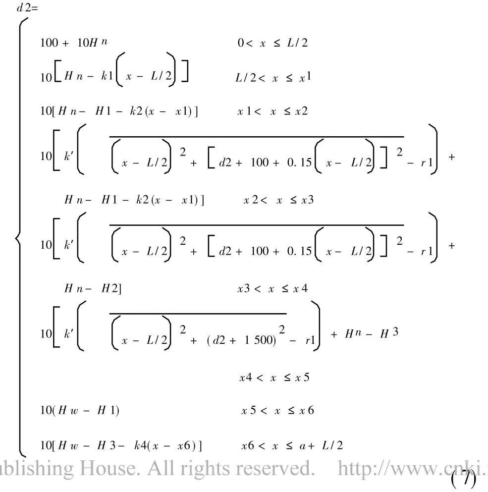
1.4 Establishing mathematical model
From Fig.2 we can see that the limit height of obstacles H(x,y)is a sub-function,it can be divided into seven parts D1,D2,D3,…,D7 D7:{x,y|x∈(0,L/2],y∈(100,100+10Hn]}∪{x,y|x∈(L/2,a+L/2],y∈(d1,d2]};
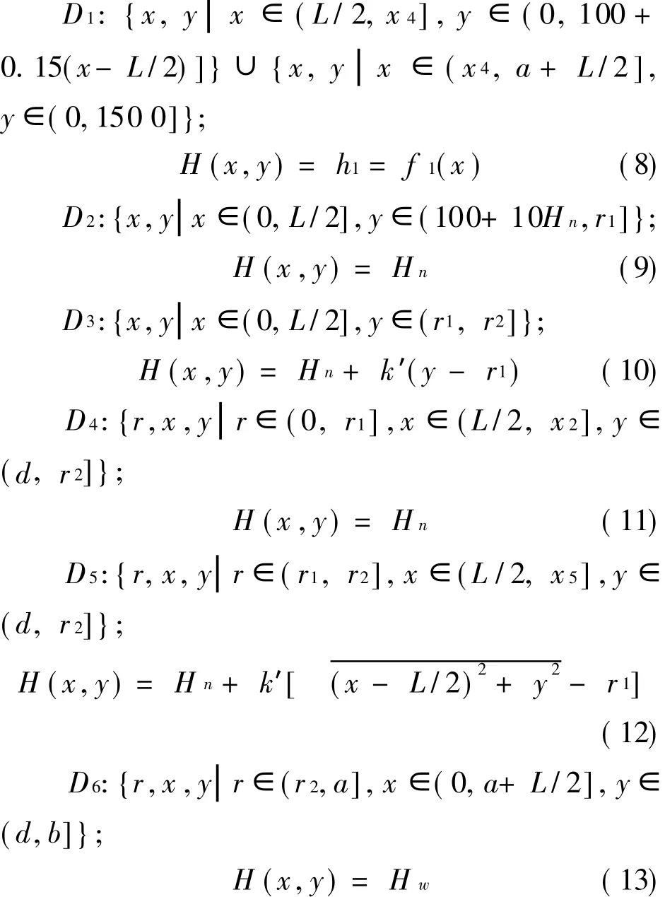
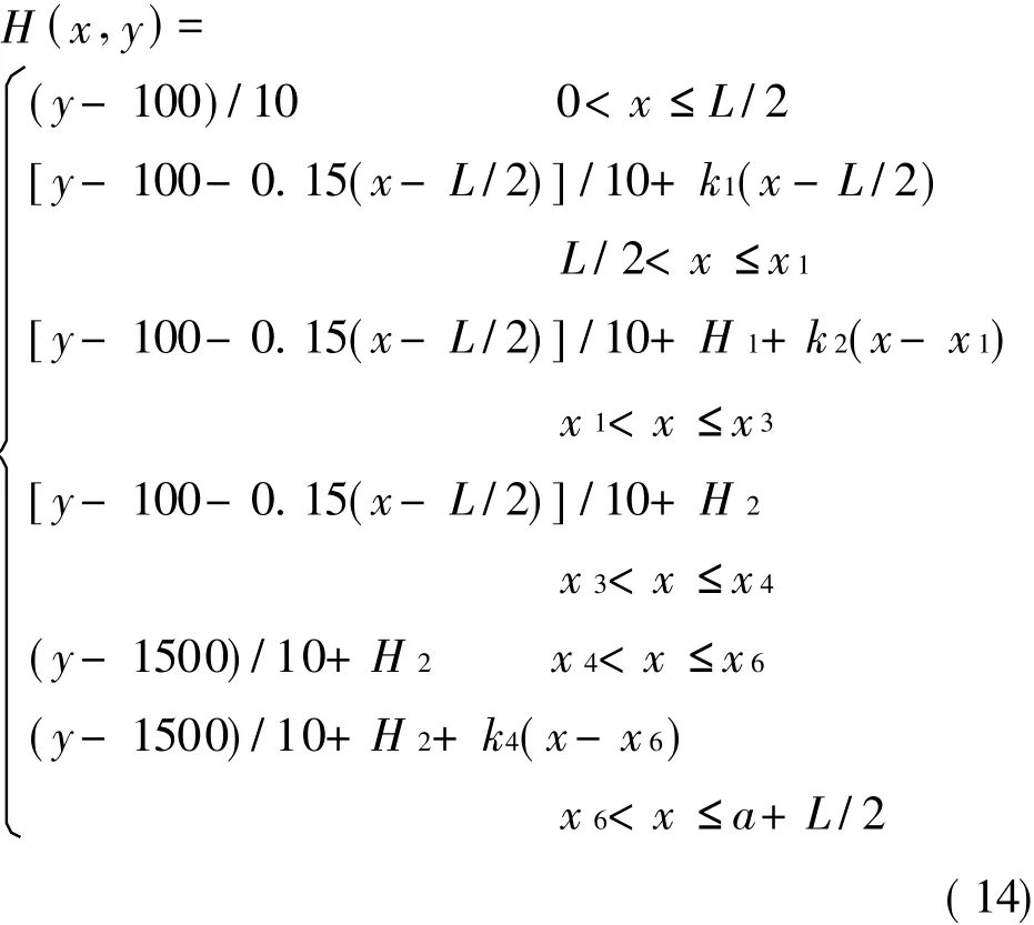
According to Eq.(14),the zone the obstacle belongs to is estimated through coordinates,and then the limit height of the obstacle can be calculated.
2 MILITARY AIRFIELD OBSTACLEFREESPACEASSESSMENT
2.1 Implementation process
In order to achieve a certain degree of accuracy,triangle(T IN)format DEM modeling is used,and the software platform is AutoCAD2006 and ArcGIS family software developed by ESRI[3].
A brief description of the implementation process as follow:
(1)Draw out the airfield free space surface layout using AutoCAD,and then convert the line file by using ArcCatalog into Polyline type of shapefile format,as shown in Fig.4.
(2)Editgenerated shapefile filesusing ArcInfo.According to the above mentioned mathematical model of airfield free space,pick points from the defined sidelines in every free space surface and enter the elevation in the property table manually.Define the edges as force line,and generate DEM of T IN format using 3-D analysis,as shown in Fig.5.
(3)Open ArcScene,and load generated T IN file,then 3-D modle can be obtained,as shown in Fig.6[4].
(4)Overlay military airfield obstacle limit surfaces to relevant airfield topographic map,as shown in Fig.7.
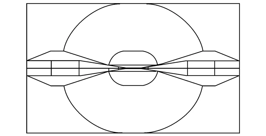
Fig.4 Plan of military airfield free space surface

Fig.5 DEM of T IN format

Fig.6 3-D display

Fig.7 Military airfield obstacle limit surfaces and relevant airfield topographic map
Airfield free space DEM overlay model established by using the above method contains corresponding elevation data.It can find the obstacle limit height anywhere through software query function.If the topographic map of corresponding military airfield is overlayed,it can be very convenient to assess the military airfield obstacle free space zone,thereby improve efficiency greatly[5].
2.2 Case analysis
As shown in Fig.7,assess airfield obstacle free space for a military airfield,A,B,C are obstacles in inner horizontal surface,outer horizontal surface and conical surface within the airfield obstacle free space respectively.According to elevation values,they are displayed by stretching.T hese three points are beyond the free space limit surface.T he information of these points can be gained using the inquiry function.Query results are shown in Fig.8.The left boxes show related layer information of the query point,and the right show detail information.T he actual elevations of A,B,C are 72,302,407 m.T he heights of free space limit surfaces are 60,286,380 m,exceeding 12,16,27 m,respectively.
3 CONCLUSION
Military airfield clearance specification is analyzed,and the mathematical model of obstacle limit surfaces for military airfield clearance is built.Based on the model,the triangle mesh elevation model of military airfield clearance is built by using ArcGIS,and the 3-D display result is obtained.Military airfield clearance obstacle is evaluated by superimposing DEM with corresponding topographic maps.Analysis result of a military airfield indicates that the actual elevations of obstacles A,B,C are respectively 72,302,407 m,the heights of clearance limit surfaces are 60,286,380 m,and the exceeding heights are 12,16,27 m,respectively.So,the obstacles of military airfield clearance are evaluated quickly and exactly by the software ArcGIS,and the efficiency of evaluating clearance obstacles can improve greatly.

Fig.8 Obstacle query results
[1] Cai Liangcai,Shao Bin,Zheng Ruhai,et al.Confirmation methods to airfield clearance zone[J].Journal of Transportation Engineering,2004(4):41.
[2] Shao Bin,Cai Liangcai,Wang Yibin.Spare runway clearance requirements analysis[J].Journal of Air Force Engineering U niversity,2003,4(6):22-25.
[3] Tang Guoan.Spatial analysis test tutorial of ArcGIS geographic information systems[M].Beijing:Science Press,2006.
[4] Cui Xianguo,Sun Hongli.T o build three-dimensional model of airfield clearance zone[J].M ine Surveying,2008,1(3):19-20,41.
[5] Chong Xiaolei,Cai Liangcai,Yang Rui.GIS-based airfield clearance assessing method[J].Mapping Bulletin,2002(11):52-53,63.
猜你喜欢
湘潮(上半月)(2022年8期)2022-12-12
科技进步与对策(2022年16期)2022-08-30
交通科技与管理(2022年8期)2022-05-07
辽河(2022年1期)2022-02-14
辽河(2022年1期)2022-02-14
宝藏(2021年3期)2021-04-20
衡阳师范学院学报(2020年1期)2020-05-18
音乐教育与创作(2019年8期)2019-05-16
黄河黄土黄种人(2018年1期)2018-05-25
 Transactions of Nanjing University of Aeronautics and Astronautics2011年3期
- Transactions of Nanjing University of Aeronautics and Astronautics的其它文章
- 冷却润滑介质对钛合金Ti6Al4V加工性能的影响
- 温度变化下基于兰姆波的复合材料结构损伤识别
- 基于因果图的微小型涡喷发动机安全性分析
- 基于OPNET的低轨卫星的点波束确定算法
- 基于遗传EM 算法的航班延误状态空间模型
- 基于多GPU的大型线性和非线性方程组的求解