Study on the impact of particle perturbation on yaw characteristics of aircraft at high angles of attack
2011-11-08 01:26YUKunlongJINLingZHUMinghong
空气动力学学报 2011年4期
YU Kun-long,JIN Ling,ZHU Ming-hong
(1.School of Aeronautics,Northwestern Polytechnical University,Xi'an 710072,China;2.China Aerodynamics Research& Development Center,Mianyang,621000,China)
0 Introduction
With the demand of high maneuverability and agility for the modern fighter,extensive investigation has been conducted on asymmetric separation vortices at high Angles Of Attack(AOA).A large number of experimental and computational investigations have shown that the forebody asymmetric vortices at AOA are the direct cause of side force.The asymmetric vortices have strong non-linear effects on aerodynamic characteristics and the direction and value of the side force is determined by these vortices with asymmetric intensity and locations.The physical mechanism of the forebody asymmetric flow has not yet been fully demonstrated due to the complexity of the flow phenomenon and many other factors[1-4].
The experimental research of the impact of small-particle-perturbation of aircraft nose on the yaw aerodynamic characteristics of typical fighter at high AOA was carried out in the Ф3.2m production wind tunnel of Low Speed Aerodynamics Institute of China Aerodynamics Research&Development Center(CARDC-1).The results show that the small-particle-perturbation on the aircraft nose where the circumferential angle is ±45°has certain impact on the yaw aerodynamic characteristics of fighter at high AOA.In this paper,the impact mechanism of the small-particle-perturbation at the circumferential angle of ±45°is studied by using the Computational Fluid Dynamics(CFD)method on basis of the flow vortices structure simulation.
1 Experiment introduction
The experiment was made in the Ф3.2m wind tunnel of CARDC-1.The standard model on wire sting support with internal balance was the YF-16 fighter in 1:9 scale.The experiment was made with free transition and all rudder angles are set to zero degree in the basic state.The main geometric parameters of the aircraft used in current research are:wing area(reference area):S=0.3210m2,Mean Aerodynamic Chord(MAC,used as reference length):bA=0.3704m,wing span:l=0.9815m.
The small-particle-perturbation experimentwasa-chieved by pasting a small particle with diameter of 0.6mm to the nose tip.The definition of the circumferential angle(Φ)of the particle location is shown in fig.1 (with Φ =0°corresponds to the plane of symmetry of the windward side of the aircraft).

Fig.1 The schematic diagram of Particle图1 机头颗粒示意图
2 Mathematical model
2.1 Numerical methods
The governing equations are the three dimensional compressible Reynolds-Averaged-Navier-Stokes(RANS)equations:
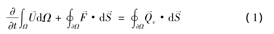
The convective terms are discretized with a Roe's fluxdifference splitting with three order MUSCL interpolation[5].The steady flow fields are obtained by using the implicit LU-SGS algorithm[6].Turbulent viscosity is calculated by using the one-equation Spalart-Allmaras model[7].
2.2 Configuration and flow condition
The structured grid,which is clustered in the wallnormal direction,is used in the near-wall regions to resolve the boundary layer,and the unstructured grid is used in the outer region.The total grid cells is about 5.4 millions.The configuration and computational grid is illustrated in Fig.2 .The inflow Mach number is Ma=0.2,and the Reynold number based on MAC is Re=2.42 ×10⁶,side slip angle β =0°.
A 5×17×5 grid block,located on the wall near the nose(Φ = ±45°),is used as the micro-perturbation particle in the numerical simulation(See Fig.3 ).The size of the particle is about 0.49mm × 0.62mm × 0.43mm(the particle is not a square column due to the irregularity of the gird near the nose).
In order to study the impact of small-particle,three cases were considered:the basic state with no particle,particle on left side(Φ =45°),and particle on right side(Φ = -45°).The computational girds for Φ =45°and Φ = -45°case are generated to be identical,except the nose parts on left and right side of the vertical central plane are exchanged.

3 Data processing
In this paper,all the force coefficients and moment coefficients are calculated with respect to the body axis system in the numerical simulation study and experimental research.The details of definitions and other related information can be found in《GB》.
4 Results and analysis
4.1 Comparison of calculated and experimental results
The comparison of calculated and experimental aerodynamic force coefficients for no perturbation to the basic state are shown in Fig.4 .It can be seen that the distribution of calculated results is consistent with the experimental data at AOA between 0°and 90°,especially the lift and drag coefficient in linear section.The angle of attack region,where the numerical results predict large value of side force,yawing moment and rolling moment,is correspond with the experimental data.These suggest the variation of aerodynamic forces with angles-of-attack is consistent with the experimental data,and the numerical methods used in this paper are appropriate to the research of the asymmetric vortices of aircraft at high AOA.
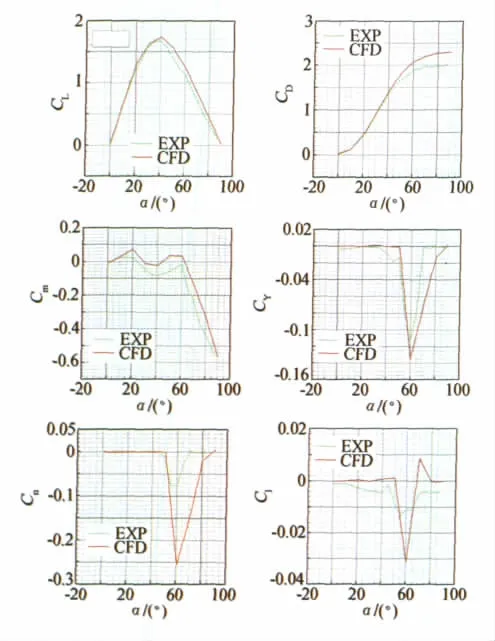
Fig.4 The comparison between CFD and experiment for aerodynamic force coefficients图4 计算与试验结果对比
4.2 Aerodynamic force of particle perturbation
The aerodynamic force coefficients result from the simulation of the case with no particle,the case with particle on the left(Φ =45°),and the case with particle on the right(Φ = -45°)are shown in Fig.5 .It is easy to see that,(1)the values of side force coefficients CYand yawing moments coefficients Cnfor the three cases are approximately zero at AOA from 0°to 30°.The nonzero CYand Cnappear at AOA lager than 30°,and the maximum values of side force and yawing moments coefficients appear at AOA from 50°to 60°.With the further increase of the AOA,CYand Cndecrease and become approximately zero at AOA lager than 80°.(2)The longitudinal aerodynamic forces for the left particle case are consistent with those of the right particle case,except the yaw aerodynamic characteristic have equal value and opposite direction.The difference between no particle and left particle case results is relatively small.Together with the experimental results,we can see that in the case of no particle case,the direction of side aerodynamic force is random at high AOA;and the particle on nose tip can fix the direction of side force as well as yawing moments coefficients in certainty direction.
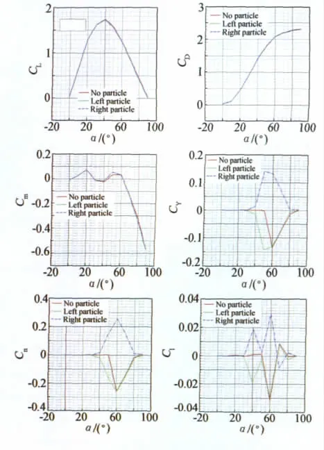
Fig.5 The effect of nose small particle with different rotation angle图5 颗粒微扰动影响
4.3 Flow mechanism of impacts of particle perturbation
To study the mechanism of small-particle impacts,we will focus primarily on the 60°AOA situation,since the maximum of CYand Cnappear in this region(see Fig.4 and Fig.5 ).
The pressure distribution on the leeward and the windward side of aircraft for no particle,left particle(Φ =45°)and right particle(Φ = -45°)cases are shown in Fig.6 and Fig.7 respectively.For the leeward side,the pressure distribution of the left particle case and the right particle case have mirror symmetry to each other with respect to the vertical central plane,which is consistent with the aerodynamic force results discussed above(as shown in Fig.6 ).The pressure distribution on the windward side for the all three cases are close to each other as shown in Fig.7 .The result demonstrates that the asymmetric vortices on the leeward side is the reason for asymmetric aerodynamic force of aircraft at high AOA.
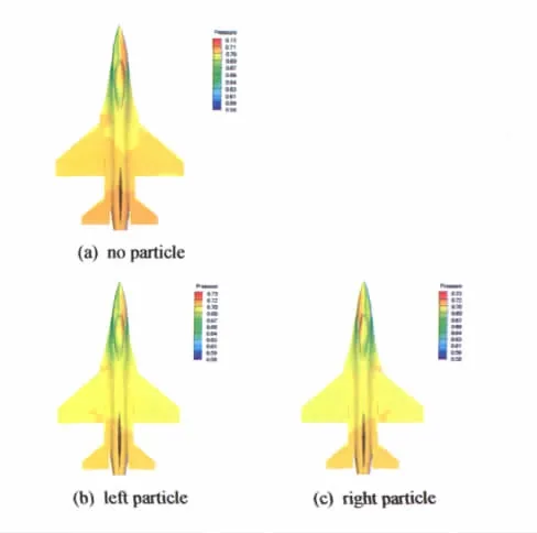
Fig.6 The pressure distribution of leeward side for aircraft(α =60°)图6 背风面压力分布(α=60°)

The pressure coutours and streamlines around nose of aircraft within several millimeters for the above three cases are shown in Fig.8 .We can see that two asymmetric vortices shed from the nose,the one shed from the side of smallparticle is stronger than the other one,which make the flow on the small-particle-side move faster than the opposite side,from windward to leeward of the forward fuselage.Therefore,a bigger separation bubble is induced by the stronger vortex on the small-particle-side,which lead to strongly asymmetric flow pattern in the nose area.In addition,the vortices structure for the no particle case are strongly resembles the left particle case,which is consistent with the aerodynamic force results above.
The pressure coutours and streamlines around 100mm scales of the forward fuselage for the three cases are shown in Fig.9 .The asymmetric vortices shed from the nose are still exist in this zone.
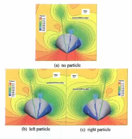
Fig.9 The pressure contours and streamlines around zone 100mm of aircraft(α =60°)图9 飞机头部100mm截面附近的压力云图和流线图(α=60°)
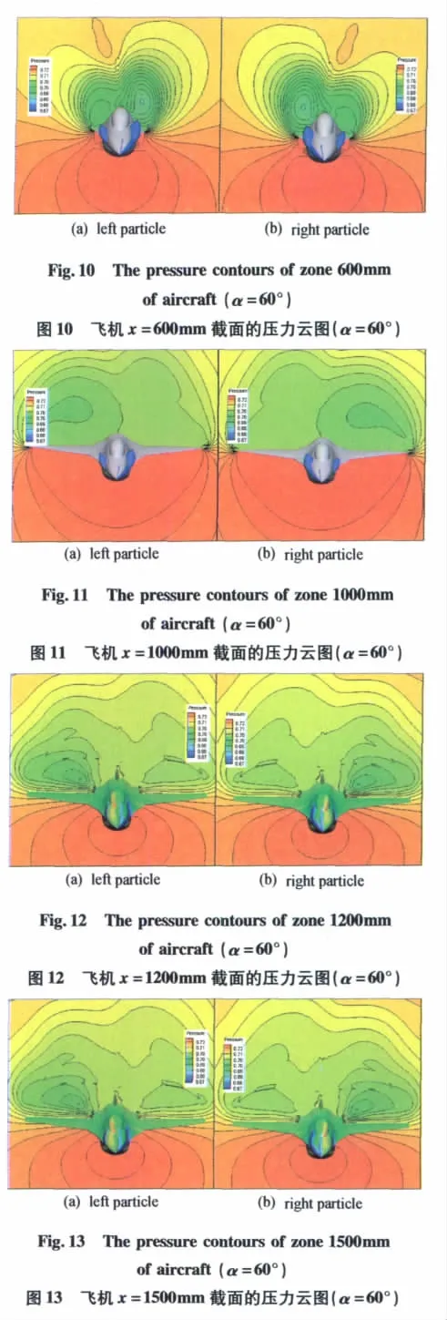
In Fig.10 - Fig.13,the pressure coutours located at x=600mm、x=1000 mm、x=1200 mm and x=1500 mm from the nose are shown for left particle and right particle case.Together with the pressure coutours of leeward shown in Fig.6 ,we can see that the asymmetry on the leeward side decreases from the aircraft nose gradually,and the relative strength of the two asymmetric vortices become slightly converse behind the end of the strake wing.Because of the side force pointing to the small-particle-side,the conclusion that the main side force is induced by the asymmetric vortices around the nose of aircraft is demonstrated.
5 Conclusion
Through the analysis of CFD results and experiments data,the following conclusions can be made:
a.The particle of nose tip at the circumferential angle of ±45°has great impacts on the yaw characteristic,and it can fix the direction of side force at high angles of attack;
b.On basis of the flow vortices structure observation,it is indicated that the vortex shed from the small-particle side of the aircraft nose at the circumferential angle of±45°is stronger than the opposite one.And it is the stronger vortex that induces a stronger separated bubble on the lateral side of the forward fuselage,which lead to large side force at high angle of attack.
[1]LAMONT P J and HUNT B L.Pressure and force distributions on a sharp-nosed circular cylinder at large angles of inclination to a uniform subsonic stream[J].Fluid Mech.1976,76(3):519 -559.
[2]HALL R M.Forebody and missile side forces and the time analogy[R].NASA Langley Research Center,AIAA 87 -0327.
[3]MOSKOVITZ C A,HALL R M and DEJARNETTE F R.Effects of surface perturbations on asymmetric vortex flow over a slender body[R].AIAA -88 -0483.
[4]CHEN X R,DENG X Y,et al.Influence of nose perturbations on behaviors of over slender body[J].ACTA Mechanica Sinica,2002,18(6):581 ~589.
[5]HIRSCH C.Numerical computation of internal and external flows volume 1:Fundamentals of Computational Fluid Dynamics[M].John Wiley & Sons,2007.
[6]JAMESON A and YOON S.Lu implicit scheme with multiple grid for the Euler equations[M].AIAA paper No.86 -0105,1986.
[7]SPALART P R and ALLMARAS S R.A one-equation turbulence model for aerodynamic flows[R].AIAA paper 92 -0439,1992.
猜你喜欢
昆钢科技(2022年4期)2022-12-30
小型微型计算机系统(2021年12期)2021-12-08
现代仪器与医疗(2021年5期)2021-12-02
数学小灵通(1-2年级)(2020年9期)2020-10-27
当代贵州(2019年41期)2019-12-13
VOGUE服饰与美容(2019年10期)2019-12-02
福州大学学报(自然科学版)(2016年5期)2016-03-15
建筑工程技术与设计(2015年8期)2015-10-21
中国科技纵横(2014年24期)2014-12-11
四川党的建设(2014年9期)2014-08-23