
Fatigue Design Criteria for Welded Bridges in the U.S.
2011-12-28 06:05JohnFisherSchoolofCivilEngineeringLehighUniversityBethlehemPAUSA
重庆交通大学学报(自然科学版) 2011年2期
John W.Fisher(School of Civil Engineering,Lehigh University,Bethlehem,PA,USA)
1 Introduction
The possibility of fatigue cracking under relatively high stress range conditions was demonstrated by the steel beam bridges(Fig.1)of the AASHO Road Test in 1960[1].
Fatigue crack growth has occurred in bridge structures and components since the 1970’s.Cracks were first observed in coverplated bridge girders(Fig.2)located on an interstate highway which carried a high volume of truck traffic causing large numbers of cyclic stress[2].

Fig.1 Fatigue crack at end of coverplated beam图1 梁端疲劳裂缝

Fig.2 Typical fatigue crack found in 1970 from bridge in service图2 在役桥梁(1970年)发现的典型疲劳裂缝
Early fatigue specifications in the U.S.originated from railway bridge design,which required reductions in allowable stress when members were subjected to load reversal[3].
During the 1940’s both AREA and AASHO used the AWS bridge specifications for welded structures.These provided for three load cycle conditions and allowable stresses were expressed in terms of the maximum stress and varied with the stress ratio,R,defined as the algebraic ratio of minimum and maximum stress.In 1965,AASHO adopted steel bridge fatigue provisions based on the existing test data which was primarily on small test specimens and limited specimens and it was generally assumed that 2 million cycles was the fatigue limit or infinite life condition for all details.These details were divided into different classifications for fatigue lives of 100,000,500,000 and 2,000,000 cycles of maximum stress caused by passage of the HS-20 design truck(Fig.3)based on the type of road and the average daily truck traffic(Table 1).

Fig.3 HS-20 design truck used for fatigue design,1965 -1994图3 1965—1994年用于疲劳设计的荷载车HS-20
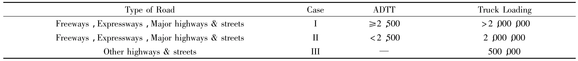
Table 1 Stress cycles for main(longitudinal)load carrying members(1965-1994)表1 承担主荷载构件的应力循环
The allowable fatigue stress was still expressed in terms of the maximum stress and was derived from the modified Goodman diagram as seen in Fig.4 with provisions for stress ratio and steel strength.

Fig.4 Goodman diagram and allowable design maximum stress provisions图4 Goodman图和容许设计最大应力条款
It was not possible to provide a statistical analysis of the design factors thought toinfluencefatigue strength as duplication was rare and variables were not controlled.
2 Laboratory Tests of Welded Girders
To overcome these limitations an extensive series of fatigue studies were carried out at Lehigh University starting in 1967 and continuing into the 1980’s.These studies used statistically designed experimental programs under controlled conditions,so that analysis of the data could reveal the significance of the parameters believed to be important in fatigue behavior[4-7].The substantial amount of experimental data developed on steel beam details showed that the most important factors that govern the fatigue strength are the stress range and the type of detail.Fig.5 shows the test data for coverplated steel beam details on both rolled and welded beams with 3 grades of steel(yields of 250MPa,350MPa and 700MPa),several levels of minimum stress and a variety of geometrical conditions.
The test results show clearly that only the stress range was the controlling stress variable and that the type of steel and section as well as the type of geometrical detail were not significant.The test data had a log normal distribution of cyclic life at all levels of stress range.Stress range means that only the live load and impact stresses need to be considered when designing steel details for fatigue.These findings were observed to be applicable to every beam and detail examined.The ratio of minimum to maximum stress,R,did not affect the stress range to cycle life relationship.The existence of residual stresses from welding is largely responsible for the fact that the R ratio is not a significant factor in the stress range cycle life relationship.Measurements shown in Fig.6 verify the existence of high tensile residual stresses at the weld toe where the initial stages of fatigue crack growth and most of fatigue life occurs in as-welded structures.

Fig.5 Test data for coverplated steel beams图5 钢盖板梁试验数据

Fig.6 Residual stresses measured at the weld toe图6 焊缝脚趾处残余应力测试值
The lower bound stress range cycle life relationships are plotted in Fig.7 for all of the experimental tests that were available up to 1986[7]for each design category.It is apparent from Fig.7 that the assumption in 1965 that the fatigue limit occurred at 2 million cycles is only applicable to base metal(Category A).

Fig.7 Lower bound S-N curves for design stress range for Categories A to E’图7 A到E类设计应力幅度S-N曲线下限
Each subsequent Category provides a lower bound stress range limit that occurs at cycle lives between 2 million and 20 million as the Categories go from Category B to Category E’.This lower bound fatigue limit for constant amplitude test data is a crack growth threshold that has been verified for Categories C,E and E’out to 100 million cycles.
The slopping S-N curves have an exponential relationship between stress range and life that is provided by

Where,Cfis a constant value for each Category of detail;Sris the design stress range.This relationship is provided in the current AASHTO specifications.
3 Variable Loading
It is well established that bridge structures are subjected to a random variable loading which results in a wide band skewed stress range spectrum.Fig.8 shows a typical stress range histogram for a bridge girder with cover plates.The most widely used method to account for cumulative damage is the Miner hypothesis[8].

Fig.8 Stress range histogram for a category E图8 E类应力幅度直方图
Variable stress cycle damage is accumulated in proportion to the relative frequency of occurrence of each level of stress range.Several studies were undertaken between 1971 and 1993 to evaluate the applicability ofthe cumulative damage criteria such as Miner’s Rule[9-11].These studies indicated that Miner’s linear damage hypothesis provided a means of relating random variable stress cycles to constant cycle data.An effective stress range can be developed using Miner’s linear fatigue damage relationship Σni/Ni=1 together with the exponential relationship provided by Eq.(2)as

Where,γiis the frequency of occurrence of stress range Sri.
The long life tests carried out in Reference[11]are shown in Fig.9 for welded web attachments.These random variable tests are seen to provide a good method of transforming the variable stress range spectrum into an equivalent effective stress range.

Fig.9 Comparison of the variable load tests with the constant amplitude tests图9 可变荷载试验与恒定振幅荷载试验比较
These tests also demonstrated that if maximum stress cycles exceeded the constant amplitude fatigue limit by more than 0.01%,all of the stress cycles below the fatigue limit contributed to the damage and had to be considered in the effective stress range.
4 Fatigue Design since 1994
In 1994 AASHTO made use of the random variable truck loads on the U.S.roads to determine an effective fatigue truck that represented all of the trucks greater than 20 kips(90kN)[12].Fig.10 shows that gross vehicle load spectrum between 1970 and 1987.An effective GVW truck was developed using the relationship provided in Eq.(2)[12].Fig.11 shows the resulting fatigue truck that has been used by AASHTO since 1994.
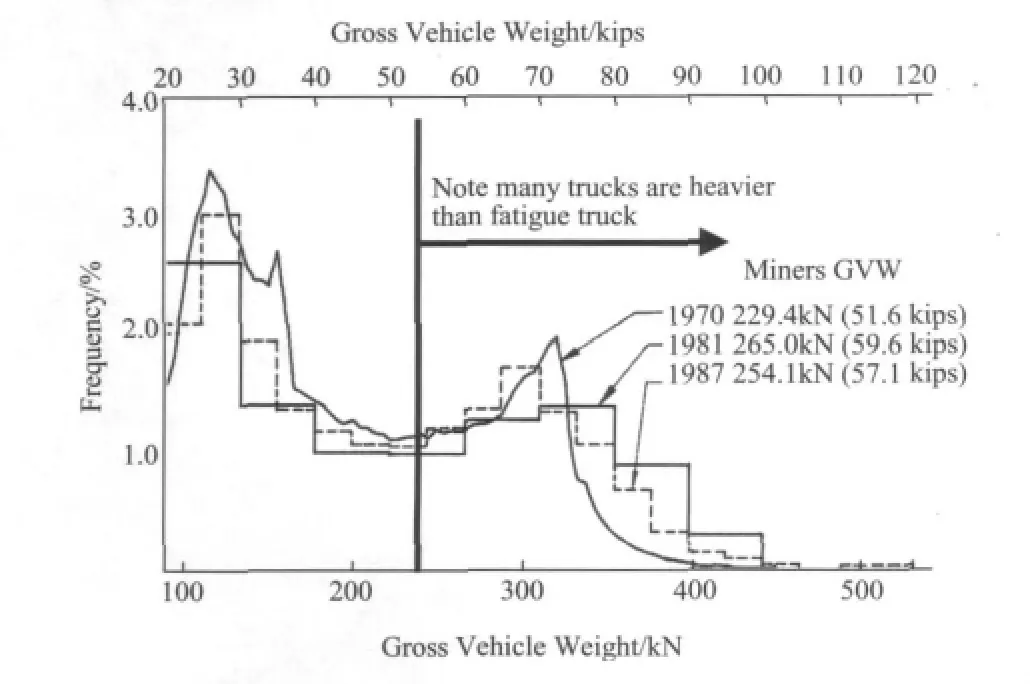
Fig.10 Gross vehicle weight spectrum observed between 1970 and 1987图10 1970—1987年观察的车辆总重量谱

Fig.11 Fatigue truck(HS-15)used to design bridges for resistance图11 用于桥梁抗力设计的疲劳荷载车辆
The fatigue truck with 15%impact provides the effective load for the variable load spectrum that the bridge will be subjected to.If the cycle frequency is great,the maximum stress range in the variable spectrum must not exceed twice the stresses generated by the fatigue truck.This is shown schematically as case 3 in Fig.12.

Fig.12 Effective fatigue resistance lies along the fatigue resistance curve when the constant amplitude fatigue limit is exceeded by 0.01%图12 恒定振幅疲劳极限超过0.01%时有效疲劳抗力与疲劳抗力曲线一致
The use of a multiplier of 2 for most bridge details is based on the fact that stress range measurements of hundreds of bridges in service for over 50 years have demonstrated that their actual live load stress range spectrum is no greater than one half to two thirds of the maximum stress predicted from the maximum loads.Hence the variable spectrum is adjusted for these observations as illustrated in Fig.13.

Fig.13 Adjustments to the variable load spectrum to reflect actual measurements of stress range in bridge structures图13 桥梁结构中影响实测应力范围的可变荷载谱的调整
Hence,the AASHTO fatigue limit state load range for primary members is taken as 2×HS-15 or HS-30(108kips 480kN)for the effective maximum stress.For orthotropic decks it is required to be 3×HS-15(162kips 720kN)with the single axle loads placed on dual axles.
5 Distortion Induced Cracking and Secondary Stresses
Since the 1970’s web gap cracking has been observed in many bridges built between 1950 and 1980.These web gaps occurred as a result of a rule adopted after WWII that you should not weld transverse to the tension flanges of girders.This was based on experience with early welded bridges in Europe in the 1930’s.As a result,the three dimensional behavior at transverse connection plates for transverse floor-beams and cross-frames resulted in very small displacements and very high stress range cycles in these web gaps.Typically these gaps were 10mm to 50mm between the longitudinal welds of the web-flange connection and the transverse welds that attached the connection plates to the web.Fig.14 shows a typical example of distortion induced cracking at the weld end of the transverse connection plate and along the toe of the web to flange weld.Distortion induced secondary stresses that result in fatigue cracks are found in every type of bridge structure.They include simple and continuous span girder bridges as illustrated in Fig.14,to box structures,tied arches(Fig.15),truss systems and many others[13-15].Often these cracks can be stopped by drilling holes at the crack tips.More often they require corrective action to prevent further web gap distortion by providing positive connections that prevents distortion between the gap.Another option is to soften the connection by increasing the size of the gap a significant amount.

Fig.14 Web gap cracking in the girder web图14 梁腹板裂缝

Fig.15 Cracking in the floor-beam web gap at the connection to a tie girder图15 楼板、梁板腹板裂缝
The AASHTO specifications require positive attachments between web gaps so the distortion induced cracking is minimized.
During the past decade fractures have developed in several bridges as a result of high triaxial stresses in very small web gaps(less than 6mm)without any detectable fatigue crack growth.Fig.16 shows the fractures that suddenly occurred in the Hoan Bridge at the small or negligible web gap between the transverse connection plate and a lateral gusset plate[16].These sudden brittle fractures resulted from the restraint stresses from weld shrinkage and dead load stress and the geometric crack-like condition that resulted from the intersecting gusset plate and the transverse connection plate.The very small web gap created a triaxial stress state that did not allow yielding to occur and resulted in stresses in the gap that exceeded the yield point by a substantial margin.This resulted in fracture under low service temperatures.The nature of the web crack development resulted in a detail that is not inspectable.
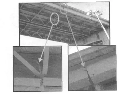
Fig.16 Restraint induced cracking from the triaxial stresses at connection plates图16 连接板三向应力约束裂缝
6 Summary
This paper provided an historical overview of the development of fatigue design provisions in the US,which has been adopted in specifications around the world.These provisions,including improved detailing practices,were developed based on extensive research and case studies.Implementation of the guidelines and improved material has limited fatigue cracking and brittle fracture in newer constructions.Fatigue of steel bridges under traffic loading is the most significant issue affecting the service performance of aging transportation infrastructure.Without timely intervention these cracks can lead to brittle fracture in steels having less than adequate toughness.Historically most of the fatigue cracking of the welded steel bridges in the USA occurred at cover plate and similar attachment details,as well as at the web gaps from distortion.The attachment details are the most severe of the fatigue critical details,which are characterized by crack growth at the weld toe.Distortion induced fatigue cracking in the web gaps may be solved by proper detailing that eliminates the secondary stresses driving these cracks.In most cases,the web-gap-cracking can be prevented by rigidly connecting the attachment plates to the tension flange.Where the distortion is displacement controlled,the stresses can be reduced by increasing the flexibility of the connection.If distortion is limited,holes may be drilled or cored at the crack tips to temporarily arrest propagation.Triaxial stresses developing in overly constrained small web gaps can cause brittle fracture without any prior fatigue crack growth.When the cumulative stress ranges in the variable stress spectrum exceeds the CAFL by 0.05%or more of the total stress cycles in the distribution,the fatigue resistance of the attachments is given by the extension of the linear sloped part of the S-N curve below the CAFL.An infinite life may be assumed when the cumulative exceedence of the stress cycles beyond the CAFL is limited to 0.01%of the total.Most structures carry enough truck traffic to justify designing them for an infinite fatigue life,especially the deck elements.
Acknowledgements:The author acknowledges those organizations that supported the research into the fatigue behavior of steel details carried out at the Fritz Engineering Laboratory and ATLSS Laboratories,Lehigh University.They include NCHRPTRB;FHWA,U.S.Department of Transportation;the Pennsyl-vania Dept.of Transportation;the U.S.Navy;the Canadian National Railroad;the New York State DOT;the New York City DOT;and the Triborough Bridge and Tunnel Authority.Thanks are also due colleagues and research students who worked with the author over the past 50 years.They include B.T.Yen,A.W.Pense,G.R.Irwin,K.H.Frank,M.A.Hirt,P.Albrecht,R.Jaccard,N.Zettlemoyer,H.Hausammann,D.R.Mertz,P.Keating,C.Menzemer,R.H.Dexter,G.L.Kulak,A.Nussbaumer,R.E.Slockbower,D.J.Klingerman,B.M.Barthelemey,J.A.Edinger,D.C.Wagner,R.Connor,W.J.Wright,B.Metrovich and S.Roy.
[1]Fisher J W,Viest I M.Fatigue Life of Bridge Beams Subjected to Controlled Truck Traffic[C]//Preliminary Publication.7th Congress.Rio de Janeiro:IABSE,1964:497-510.
[2]Fisher J W,Slockbower R E,Hausammann H,et al.Long-time observations of a fatigue damaged bridge[J].Proceedings ASCE,1981,107(TC1):55-71.
[3]Fountain R S,Munse W H,Sunbury R D.Specifications and design relations[J].Journal of the Structural Division,ASCE,1968,94(ST12):2751-2767.
[4]Fisher J W,Frank K H,Hirt M A,et al.Effect of Weldments on the Fatigue Strength of Steel Beams[R]//NCHRP Report 102,Washington,D.C.:Transportion Research Board,National Research Council,1970.
[5]Fisher J W,Albrecht P A,Yen B T,et al.Fatigue Strength of Steel Beams with Transverse Stiffeners and Attachments[R].Washington,D.C.:Transportation Research Board,National Research Council,1974.
[6]Fisher J W,Hausammann H,Sullivan M D,et al.Detection and Repair of Fatigue Damaged in Welded Highway Bridges[R]//NCHRP Report 206.Washington,D.C.:Transportafion Research Board,National Research Council,1979.
[7]Keating P B,Fisher J W.Evaluation of Fatigue Tests and Design Criteria on Welded Details[R]//NCHRP Report 286.Washington,D.C.:Transportafion Research Board,National Research Council,1986.
[8]Miner M A.Cumulative damage in fatigue[J].Journal of Applied Mechanics,1945,12:111-119.
[9]Schilling C G,Klippstein K H,Barsom J M,et al.Fatigue of Welded Steel Bridge Members Under Variable-Amplitude Loadings[R]//NCHRP Report 188.Washington,D.C.:Transportafion Research Board,National Research Council,1978.
[10]Fisher J W,Mertz D R,Zhong A.Steel Bridge Members under Variable Long Life Fatigue Loading[R]//NCHRP Report 267.Washington,D.C.:Transportafion Research Board,National Research Council,1983.
[11]Fisher J W,Nussbaumer A,Keating P B,et al.Resistance of Welded Details Under Variable Amplitude Long-Life Loading[R]//NCHRP Report 354.Washington,D.C.:Transportafion Research Board,National Research Council,1993.
[12]Moses F,Schilling C G,Raju K S.Fatigue Evaluation Procedures for Steel Bridges[R]//NCHRP Report 299.Washington,D.C.:Transportafion Research Board,National Research Council,1987.
[13]Fisher J W.Bridge Fatigue Guide-Design and Details[M].USA:American Institute of Steel Construction,1977.
[14]Fisher J W.Fatigue and Fracture in Steel Bridges[M].USA:Wiley-Interscience,1984.
[15]Fisher J W,Jin J,Wagner D C,et al.Distortion-Induced Cracking in Steel Bridges[R]//NCHRP Report 336.Washington,D.C.:Transportafion Research Board,National Research Council,1990.
[16]Wright W J,Fisher J W,Kaufmann E K.Failure Analysis of the Hoan Bridge Brittle Fracture[C]//Proceedings,NYC 2ndBridge Conference.Lisse:Swets & Zeitlinger,2003.
猜你喜欢
陕西水利(2022年5期)2022-07-04
北京航空航天大学学报(2022年5期)2022-06-06
四川轻化工大学学报(自然科学版)(2021年1期)2021-06-09
小资CHIC!ELEGANCE(2019年40期)2019-12-10
上海公路(2018年3期)2018-03-21
益寿宝典(2017年17期)2017-03-08
工程建设与设计(2016年8期)2016-03-11
电子设计工程(2015年16期)2015-02-27
城市道桥与防洪(2014年1期)2014-02-27
电力自动化设备(2013年11期)2013-09-18
