
Design of ANSYS-based Cathode with Complex Groove
2012-03-09 11:57FANZhijian范植坚ZHAOGanggang赵刚刚ZHANGLijua张丽娟
Defence Technology 2012年1期
FAN Zhi-jian(范植坚),ZHAO Gang-gang(赵刚刚),ZHANG Li-jua(张丽娟)
(1.School of Mechatronic Engineering,Xi’an Technological University,Xi’an 710032,Shaanxi,China;2.Institute of Oil Gas Technological,Changqing Oil Company,Xi’an 710021,Shaanxi,China)
Introduction
Since the distribution of machining gap between the surface of complex groove and cathode profile is uneven,the cathode design is so difficult that its profile must be modified repeatedly[1-3].The cosθ method was put forward by H.Tipton who defines the cathode profile as an envelope surface of all the points in a normal gap.This geometry design method which simplifies excessively the physical phenomena may introduce a large error into a complex workpiece.Lacey introduced an analytic method based on Laplace equation[4],and Marius Purcar adopted a boundary element method to iterate the nodes on the cathode boundary along normal to obtain“E”workpiece in computer[5].Leslie Bortiles simulated and processed a die[6].Bhattacharyya simulated cathode shape using a cut-and-try procedure[7].SUN Chun-hua and ZHU Di calculated the potential distribution by FEM based on direct problem,and mapped the deviation of equipotential line from the anode boundary on the cathode to modify the cathode boundary[8].
An initial cathode is obtained by cosθ method,and a parameter-transformation model is established,and then the potential distribution is calculated by ANSYS in this paper.According to the iteration criterion,the deviation is mapped on the cathode boundary,which is revised repeatedly using a boundary-adjusting method until the objective function is satisfied.Finally,the experiments were carried out.
1 Traditional Method of Cathode Design in ECM
The workpiece is dissected,of which one section is a semicircle with radius of 3 mm in X direction,and the other is a cylinder of which the angle included between two generating lines is 7.5°in Y direction,as shown in Fig.1.
Traditional method of cathode designis as follows:the cathode profile is drawn point by point according to normal gap,i.e.cosθ method,a workpiece is pre machined,and the deviation of workpiece from the blueprint is measured to modify the cathode profile.As a matter of fact,the dissolution rate of workpiece lie on not only geometry factor,but electric field distribution,conductivity and current efficiency in gap,so the cath-ode must be modified repeatedly.

Fig.1 Processed workpiece

Fig.2 Flowchart of traditional cathode design
2 Computer Aided Design of Cathode Profile
2.1 Mathematical Model
On the assumption that electrode process is in a steady-state,the parameters of electric field and electrolyte were only the function of locality,and the conductivity varies just alonΔgdirection of electrolyte flow.

where κ is conductivity,E is electric field intensity.Assuming that the surfaces of cathode and anode were considered as the equipotential surfaces of different electric potentials,the region studied is divided into micro-cells,in which conductivity is treated as a constant.One of these equipotential surfaces is sure to satisfy Laplace equation solution.
The relation between vaand v is

where vais dissolution rate of workpiece,and v is feed rate of cathode.

where n is the unit vector along potential gradient,so

2.2 Algorithms and Software Implementation
An initial cathode boundary is first using cosθ method(Fig.3),then the electric field intensity at the points of anode boundary is calculated by using FEM,and is denoted as:


Fig.3 Initial cathode
The actual distribution of electric field on anode boundary with conductivity and current efficiency varying on it is calculated according to Eq.(5):

The sum of variances in Eq.(6 -7)is intended to be the objective function:

The design variables were altered to modify the gap between anode and cathode,the iteration program compiled with Visual C++6.0 calls the value calculated by ANSYS 8.0 software,and the calculated value is iterated until the objective functional value is within the allowable error,the boundary of the cathode is designed in such way as to result in object close to actuality.
A closed region is surrounded with the initial cathode and work piece,including a processing gap,as shown in Fig.3.The design variables were just the gap,which added to coordinate of each point on anode boundary equals to that of cathode boundary.Owing to the demand of iterative,it is necessary to modify the geometric model repeatedly,so APDL is adopted for program parametric modeling,B-spline curve is applied for interpolation,and the skinning in ANSYS is used to generate a new cathode working face.According to the process the parameters were set:15%NaNO3electrolyte,78% current efficiency,25 ℃,0.117 Ω-1cm-1conductivity, 12 V voltage,4Cr2NiMoVSi specimen material,input material properties,finally meshing.

Fig.4 Electric field of gap
The modified design variable is input into ANSYS.As APDL language variable in ANSYS can not be interchanged directly with the variable in C++,the file data is read by APDL,which is written in C++file ansys_input.txt.Having gotten new data,the potential distribution is modeled by APDL again,meshed,and calculated to achieve the electric field distribution of anode boundary.The calculated boundary is compared with the actual boundary,and the difference is input into ansys_output.txt.The next iteration goes on.
The objective function is 5 at 18th iteration,the electric field distribution of anode boundary and the cathode profile were shown in Fig.5 -6,respectively.It is necessary to make the experiment for certification of error range of acceptable cathode.
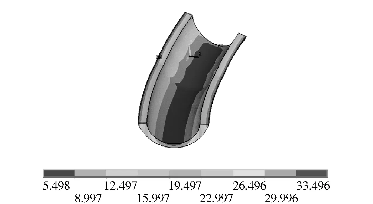
Fig.5 Electric field of anode boundary

Fig.6 Electric field on C -C section boundary
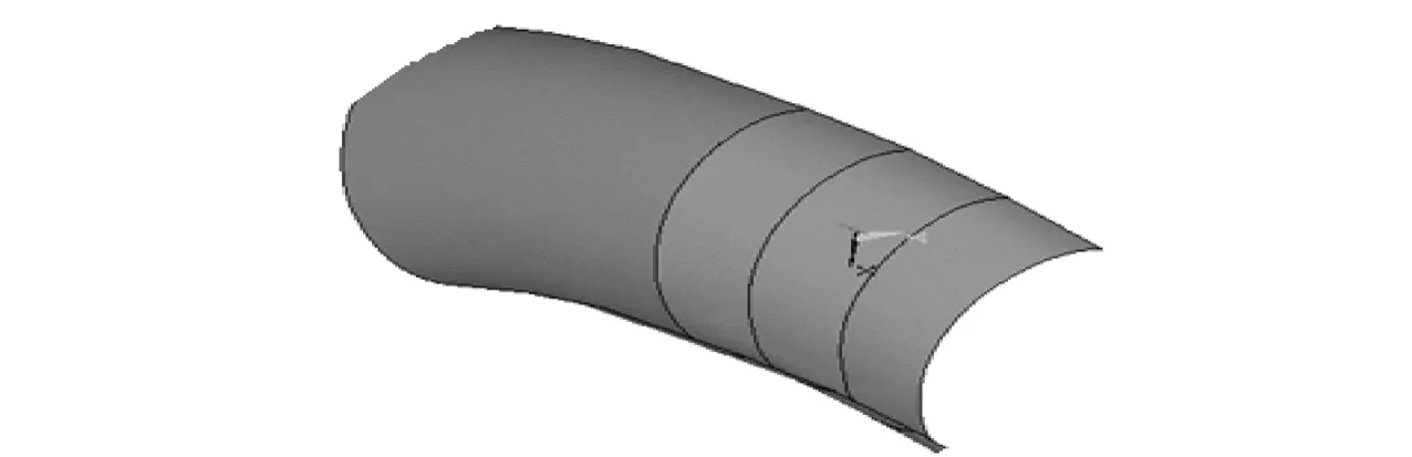
Fig.7 Cathode boundary
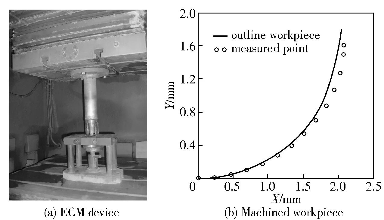
Fig.8 ECM experiment
3 Process Test
The experiments were made on MC-50VECM machine tool,the workpiece is processed with simulated cathode which is the result of 18th iteration,and the conditions of process were:15%NaNO3,12 V,feed rate of 1 mm/min,25 ℃,conductivity of 0.117 Ω-1cm-1,4Cr2NiMoVSi specimen material. The tests show that the groove dimension satisfies the requirements.
4 Conclusions
1)The initial cathode was obtained by cosθ method,a parameter model was established,and the potential distribution was calculated by using ANSYS software.Boundary-adjusting method was adopted,taking into account conductivity and current efficiency.According to the iteration criterion,the deviation was mapped on the cathode boundary.Instead of experiment,the computer was partly adopted in design.The experiments indicate that the development time of cathode is shortened by computer to some extent.
2)It is convenient to modifythe cathode profile by APDL parameter-transformation modeling.Iteration program was compiled with Visual C++6.0 calling subprogram by using ANSYS 8.0 software to analyze the distribution of electric field in gap,so that the rate of convergence can be increased.
[1]FAN Zhi-jian,LI Xin-zhong,WANG Tian-cheng.Electrochemical machining and composite electrochemical machining[M].Beijing:National Defense Industry Press,2008.(in Chinese)
[2]Zybura-Skrabalak M,Ruszaj A,The influence of electrode surface geometrical structure on electrochemical[J].Journal of Materials Processing Technology,2000,107(1-3):288-292.
[3]Mount A R.,Clifton D,Hpwarth P,et al.An integrated strategy for materials characterization and process simulation in electrochemical machining[J].Journal of Materials Processing Technology,2003,138(1-3):449-454.
[4]Lacey A A.Design of cathode for an electromachining process[J].IMA Journal of Applied Mathematics,1985,34(3):258-267.
[5]Purcar M,Bortels L,Bossche B V,et al.3D electrochemical machining computer simulations[J].Journal of Materials Processing Technology,2004,149(1-3):472-478.
[6]Purcar M,Bortels L,Bossche B V,et al.A user-friendly simulation software for 3D ECM[J].Journal of Materials Processing Technology,2004,149(1-3):486-492.
[7]Bhattacharyya S,Ghosh A,Mallik A K.Cathode shape prediction in electrochemical machining using a simulated cut-and-try procedure[J].Journal of Materials Processing Technology,1997,66(1-3):146-152.
[8]SUN Chun-hua,ZHU Di,LI Zhi-yong.ECM cathode design using numerival simulated cut-and-try[J].Machinery Design & Manufacture,2004,(6):81 -83.(in Chinese)

- Defence Technology的其它文章
- Research on Integrated Analysis Method for Equipment and Tactics Based on Intervention Strategy Discussion
- Spectral Match Optimization Based on Grey Relational Analysis
- Research on Application of Radar Decoy
- Experimental Research on Influence of Some Factors on Ejection Height of Cargo Projectile
- Research on Three-Echelon Inventory Model and Algorithm for Valuable Spare Parts in Weapon Equipment
- Experimental Investigation on Space-dispersed Double-wall Jet Combustion System for DI Diesel Engine