单晶硅等效机械特性的实验研究*
2012-06-12 09:36肖定邦侯占强王兴华吴学忠
传感技术学报 2012年8期
张 旭,李 浩,肖定邦,侯占强,王兴华,吴学忠
(国防科学技术大学机电工程及自动化学院,长沙410073)
Single crystal silicon is the most commonly used material in the microelectromechanical systems(MEMS)because of its excellent mechanical properties.The accurate mechanical parameters are foundational for designing MEMS devices and the experimental results of the Young’s modulus and Poisson’s ratio are quite different from each other because of the size effect,the processing technology,the environment and so on[1-2].So it is necessary to measure the mechanical parameters before the structural design.The Anisotropic mechanical properties ofsilicon can be described with the compliance coefficient tensor as a 6×6 matrix.It can be verified that in a crystallographic coordinate system,there are still three independent non-zero components[3].So there are at least three parameters to be measured.In addition,the measurement of the material whose mechanical parameters are anisotropic is moredifficultthan theisotropic material.Since most of the MEMS devices only take advantage of the bending and torsion characteristics of the silicon beams,single crystal silicon can be regarded as an isotropic material based on the principle of equivalent stiffness.As a result,there are only two parameters to be measured while the simplification can ensure the accuracy ofstructuraldesign.Thus we can focus on the measurement of the equivalent Young’s modulus and Poisson’s ratio of Single crystal silicon.
There are several methods for measuring the mechanical parameters of silicon,such as nano indentation test,micro tensile test,micro torsion test,and so on[4-7].But these methods usually demand complex testing instruments,and it is difficult to ensure the accuracy of the measurement of small displacement.What’s more,it is necessary for clamping device which would take great impact on the result in these contact methods.To overcome these difficulties,an effective method for the measurement is recommended by means of measuring the resonant frequency of the testing samples[8-9].It’s relatively simple and of high accuracy,moreover,the clamping setup is not needed.Based on the idea of the equivalent stiffness,the equivalent Young’s modulus and Poisson’s ratio of the slanted silicon beam which is fabricated by means of anisotropic wet etching are measured using a resonant frequency test in this paper.The relation between the dimensions of the beam and the equivalent mechanical parameters is also studied to supply the basic data for the design of MEMS devices.
1 The Principle of Equivalent Stiffness
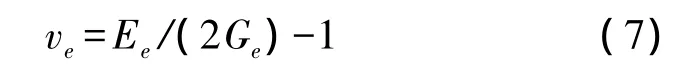
The test slanted beam is fabricated by means of the anisotropic silicon etching process,and the shape of the cross section is parallelogram.The angle between the adjacent sides is 54.74°which equals the angle between the(111)plane and the(100)plane.The schematic sketch of the beam is shown in Fig.1.The slanted beam has been used in a variety of MEMS devices,such as micromachined gyroscopes and accelerometers[10-13].The main working principle ofthe devices is based on the bending and torsion modes of the beam as shown in Fig.2.The bending axis of the beam is the inertia axis of the cross section p.
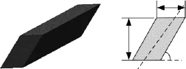
Fig.1 The silicon slanted beam
The stiffness theory of the anisotropic slanted beam is excessively complicated,so the principle of the beam whose cross section is rectangular is discussed first as an example.As shown in Fig.3,the width and height of the rectangular beam are w and h.
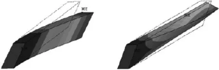
Fig.2 Bending and torsion nodes of the Beam

Fig.3 The rectangular beam
Assuming the material of the beam is orthotropic,the elastic symmetry planes are parallel to the surfaces of the beam respectively and the z-axis is the main elastic axis.According to the theory of elasticity of anisotropic material[14],the bending and torsion stiffnesses of the beam are:
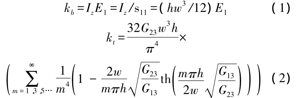
Where Izis the moment of inertia around the bending axis of the beam,E1is the Young’s modulus of the x-axis,G13,G23are the main shear modulus of the material.
Assuming the material of the beam is isotropic,the bending and torsion stiffnesses are[3]:
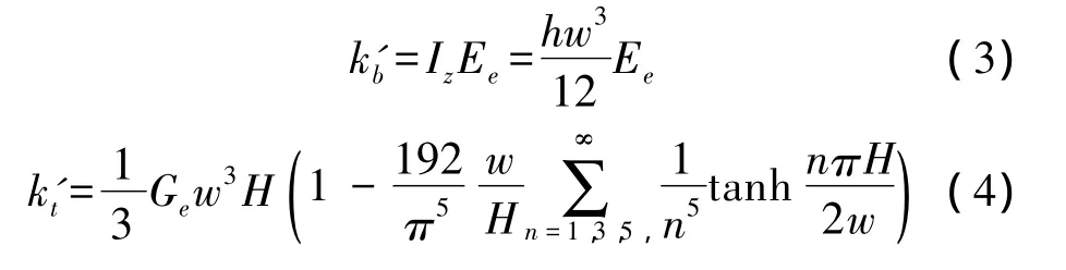
Where Eeis the Young’s modulus of the isotropic material,Geis the shear modulus of the isotropic material.By letting kb=k'b,kt=k't,we have
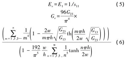
Considering the relationship between the isotropic material parameters,the equivalent Poisson’s ratio can be further obtained:
Eeand νeare the equivalent Young’s modulus and the equivalent Poisson’s ratio of the anisotropic rectangular beam.From the expression of Eeand νe,it can be inferred that there is no correlation between the equivalent Young’s modulus and the dimensions of the beam.However,the equivalent Poisson’s ratio does not only relate to the characteristic of the material,but also relate to the dimensions of the beam.Now let us consider the anisotropic slanted beam.Although the stiffness problem of the slanted beam can be transformed into the one of the rectangular beam through linear coordinate transformation,it is still impossible to find the analytical stiffness solution of the anisotropic slanted beam[15].Whereas the linear coordinate transformation does not change the rank of w and h,it can be similarly inferred that there is also no correlation between the equivalent Young’s modulus and the dimensions of the anisotropic slanted beam,while the equivalent Poisson’s ratio does not only relate to the characteristic of the material,but also relate to the dimensions of the beam.When the anisotropic beam and the isotropic beam have the same dimensions,the equivalent stiffness equals the equivalent resonant frequency.According to this conclusion,the equivalent Young’s modulus and the Poisson’s ratio of the anisotropic slanted beam are measured by experimental method using the resonant frequencies in this paper.
2 Sample Fabrication
As shown in Fig.4,the testing sample consists of the glass substrate and the silicon structure.The glass substrate on which there are some electrodes for driving and detecting is fabricated with Pyrex 7740.The(100)silicon wafer is 240 μm thick and 25%TMAH is used for anisotropic wet etching.
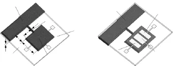
Fig.4 Schematic diagram of the test sample
In order to study the relationship between the equivalent Poisson’s ratio and the dimensions of the slanted beam,a total of eight groups of slanted beams are fabricated.The widths of the beams range from 30 μm to 240 μm at an interval of 30 μm,while the ratios of the width to the thickness range from 1/8~1 at an interval of 1/8 respectively.The main process flow for sample fabrication is shown in Fig.5.There are mainly four steps:(1)The anisotropic wet etching of the silicon wafer;(2)Etching for corrosion pit on the glass substrate;(3)The sputtering,patterning and etching of the electrode;(4)The anodic bonding of the glass substrate and the silicon wafer.The micrograph of the fabricated sample is shown in Fig.6.
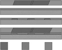
Fig.5 The fabrication process flow for test sample
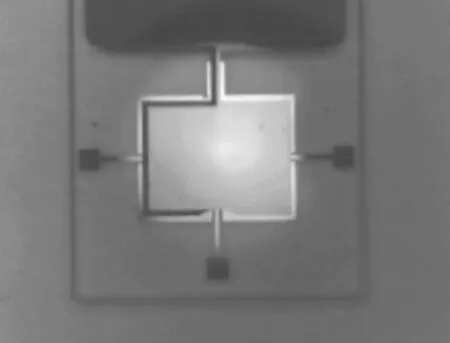
Fig.6 Micrograph of the fabricated sample
3 Results and Discussion
Sampling six specimens from each group,a total of forty-eight experiments have been carried out.In order to reduce the error,the dimensions of the samples are measured accurately.In this paper,the bending and torsion modes are characterized by electrostatic excitation with a sinusoidal signal in frequency sweep and simultaneous capacitive detection,using NF frequency response analyzer FRA5087.The bending and torsion frequency response curves of Sample G1 are shown in Fig.7.The measured dimensions and resonant frequencies of Sample G1 are shown in Table1.

Table 1 The measured dimensions and the resonant frequencies of Sample G1
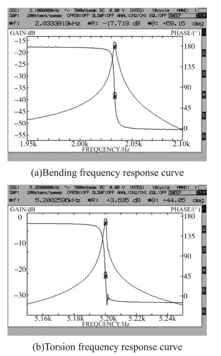
Fig.7
Considering that there is no interaction between Poisson’s ratio and the bending resonant frequency,the relation between the bending resonant frequency and the Young’s modulus of Sample G1 is obtained by ANSYS as shown in Fig.8.The measured equivalent Young’s modulus of Sample G1 is 173.1 GPa.On the basis of the fixed equivalent Young’s modulus,ANSYS is used to obtain the relation between the torsion resonant frequency and the Poisson’s ratio of Sample G1 again.As shown in Fig.9,the measured equivalent Poisson’s ratio of Sample G1 is 0.403.
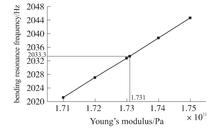
Fig.8 Young’s modulus-frequency relation
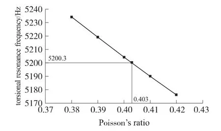
Fig.9 Poisson’s ratio-frequency relation
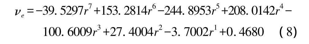
The measured equivalent Young’s modulus of each group is shown in Fig.10,and the average result of all samples is 170.51 GPa.The equivalent Young’s modulus of the slanted beam is actually the Young’s modulus in the[110]direction paralleling the longitudinal axis of the beam.The result shows that the equivalent Young’s modulus was accurately measured with a small deviation.The standard deviation is 2.08 GPa,and all data points are within 2.93%.The measured equivalent Poisson’s ratio of each group is shown in Fig.11.Then the equivalent Poisson’s ratio is fitted with polynomials in Matlab,and the polynomial of degree 7 coincides with the measured data exactly.The polynomial fitting result is:
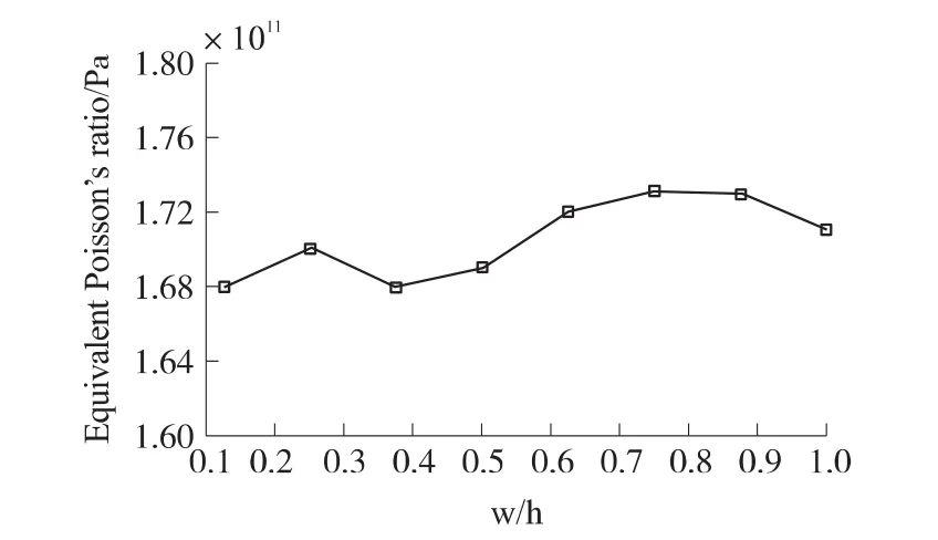
Fig.10 The measured equivalent Young’s modulus
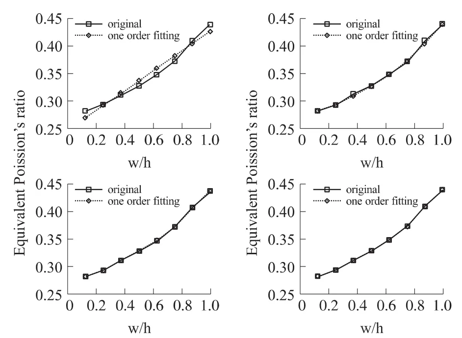
Fig.11 The measured equivalent Poisson’s ratio
From the result of the experiment,it is proved that there is no correlation between the equivalent Young’s modulus and the dimensions of the anisotropic slanted beam,while the equivalent Poisson’s ratio does not only relate to the characteristics of the material,but also relate to the dimensions of the beam.The possible reasons that affect the result come mainly from the aspects as follows:(1)the dimension measurement;(2)error of the fabrication process;(3)the frequency measurement;(4)accuracy of the finite element simulation.It is worth noting that the biggest sources of measurement error are the(1)and(2)factors.Since the measured results are based on the finite element analysis of ANSYS,it can provide the reliable mechanical parameters for the finite element design and analysis of MEMS devices.
4 Conclusions
In this paper,the single crystal silicon slanted beam is fabricated.According to the principle of equivalent stiffness,the equivalent Young’s modulus and Poisson’s ratio of the beam have been measured using a resonant test.This method does not only suit the measurement for the equivalent mechanical properties of anisotropic material,but also for the isotropic material.The measured result is closer to the widely accepted value reported in[1,4],indicating the reliability of the testing setup and procedure.
[1] Chu Jinkui,Zhang Duanqin.Research Situation and Trend of Mechanical Testing of Micro Structures[J].China Mechanical Engineering,2007,18(19):2383-2387.
[2] Jin Q H,Li T,Wang Y L,et al.Confirmation on the Size-Dependence of Young’s Modulus of Single Crystal Silicon from the TEM Tensile Tests[C]//IEEE SENSORS 2010 Conference.
[3] Bao Minghang.Analysis and Design Principles of MEMS Devices[M].Elsevier,2005:33-44.
[4] Zhang Taihua,Yang Yemin,Zhao Yapu.Measurement of Mechanical Properties of Mems Materials[J].Advances in Mechanics[J].2002,(32)4:545-562.
[5] Takahiro N,Yoshitada I,Takeshi T.Evaluation of Dimensions Effect on Mechanical Properties of Single Crystal Silicon by Nanoscale Bending Test Using AFM[J].Journal of MEMS,2000,9(4):450-459.
[6] Yi T,Li L,Kim C J,et al.Microscale Material Testing of Single Crystalline Silicon:Process Effects on Surface Morphology and Tensile Strength[J].Sensors and Actuators A:Physical,2000,83(1-3):172-178.
[7] Jin Q H,Li T,Zhou P,et al.Mechanical Researches on Young’s Modulus of SCS Nanostructures[J].J.Nanomater.,Vol.2009,Article ID319842,2009.
[8] Li X X,Ono Y,Wang Y L,et al.Ultrathin Single Crystalline Silicon Cantilever Resonators:Fabrication Technology and Significant Specimen Size Effect on Young’s Modulus[J].Appl.Phys.Lett.,Vol.83,3081-3083,2003.
[9] Mazza E,Abel S,Dual J.Experimental Determination of Mechanical Properties ofNiand Ni-Fe Microbars[J].Microsysterm Technologies,1996,2:197-202.
[10] Rödjegård H.Micromachined Three-Axis Accelerometers and Sensor Readout Electronics[D].Chalmers University of Technology,2005.
[11] Abdul Haseed Ma,Albert M Leung.Three-Axis Thermal Accelerometer Based on Buckled Cantilever Microstructure[C]//IEEE SENSORS 2008 Conference,2008:1492-1495.
[12] Andersson G,Hedenstierna N,Svensson P.A Novel Silicon Bulk Gyroscope[C]//Proceedings of International Conference on Transducers,Sendai,1999:902-905.
[13] Xiao D,Man H,Hou Z,et al.High Performance Micromachined Gyroscope with a Slanted Suspension Cantilever[C]//Proceedings of the IEEE Sensors,Christchurch,New Zealand,October 2009:467-470.
[14] Lθkhnitskii S G.Theory of Elasticity of an Anisotropic Body[M].Mir Publisher,1981:280-295.
[15] Li Yantao.A Futher Research on the Torsion Problem of a Straight Bar with Uniform Cross Section[J].Journal of Jiamusi University(Natural science edition),2001,19(1):84-86.
猜你喜欢
美与时代·美术学刊(2022年3期)2022-04-27
华人时刊(2021年17期)2021-11-12
建材发展导向(2019年10期)2019-08-24
金沙江文艺(2019年7期)2019-07-29
中国交通信息化(2019年3期)2019-06-18
中国交通信息化(2018年8期)2018-11-09
金沙江文艺(2017年4期)2017-03-31
能源(2016年2期)2016-12-01
光学精密工程(2016年2期)2016-11-07
太阳能(2016年6期)2016-09-23