
Calculation methods of lubricant film pressure distribution of radial grooved thrust bearings
2012-06-21 01:58HUJibin胡纪滨LIUDinghua刘丁华WEIChao魏超
HU Ji-bin(胡纪滨), LIU Ding-hua(刘丁华), WEI Chao(魏超)
(The State Key Laboratory of Vehicle Transmission,Beijing Institute of Technology,Beijing 100081,China)
Grooved bearings are frequently applied in industries for better load capacities.For ability of bidirectional rotating,radical grooved thrust bearings are advantageous in certain working circumstances.For a finite-width,parallel step pad slider bearing,an analytical solution with a Cartesian coordinate system has been reported[1-2].Basu[3]solved the compressible Reynolds equation over a radial groove hydrodynamic section by both finite difference and finite element methods.Song[4-6]presented a finite difference numerical analysis of the pressure distribution of mechanical liquid face seal.Rahmani et al.[7]summarized relevant literature industrial significance of step bearings.Liu et al.[8]derived a set of analytical solutions for hydrodynamic lubrication of fan-shaped thrust step bearings considering in a cylindrical coordinate.
In this paper,the hydrostatic pressure difference at surrounding boundaries is neglected.A ra-dial groove thrust bearing is considered in a cylindrical coordinate.The pressure distribution and load capacity of lubricant film are calculated by both analytical and numerical method (finite volume method),respectively.The precision and speed of numerical solutions are also discussed.
1 Problem description
In a cylindrical coordinate,a radial grooved thrust bearing with a step height ofhgis shown in Fig.1against an end face of a plane counterpart.Generally,the grooved bearing is assumed to be stationary and the end face rotates at an angular speed of ωwithrespecttotheorigin.Parameterh0istheminimumgapattheinterfaceandparametersaandbaretheinnerandouterradiusofthe annulusgeometry,respectively.Alongthecircumferentialdirection,agroovedregionisdefinedas0≤θ≤α,whilealandregionasα≤θ≤β.

Fig.1 Schematic of a grooved thrust bearing
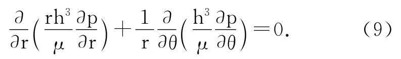
Inthispaper,weonlyconsiderhydrodynamiclubrication.Forisothermal,incompressible,andNewtonianassumptionsforlubricant,the Reynoldsequationinthecylindricalcoordinateis writtenas

whereμistheviscosityoflubricant,pisthehydrodynamicpressure,andhisthefilmthickness.
2 Lubrication analysis
ForaNewtonianlubricant,velocitiesoflubricantflowintheCartesiancoordinateareexpressedas[1]

whereU= -rωsinθandV=r ωcosθaretheend face’svelocities.
UtilizingtherelationshipsbetweentheCartesianandcylindricalcoordinates,thevelocitiesof Eqs.(2)(3)canbetransformedinthecylindrical coordinateas[3]

The flow rate is an integration of the velocity with respect toz,therefore:

The boundary conditions for the flow filed are as follows:

By applying the mass conservations to link the two regions,the pressure distribution of lubricant film can be calculated as shown in the next section.
3 Calculational methods
3.1 Analytical method
The radial grooved bearing has a constant lubricant thickness in each region.The Reynolds equation in Eq.(1)can be further reduced to Laplace partial differential equation:
Thus,by applying exact solutions of Laplace equation combined with boundary conditions,the pressure distribution of film can be obtained[8]:
In the grooved region,0≤θ≤α

In the land region,α≤θ≤β

whereR=a/b,λ=r/b,γ=nπ/lnλ,g=(H0+1)3coth(γα)+H30coth[γ(β-α)],H0=h0/hg.
Theloadcapacitycanbeexpressedas[8]

Although the analytical solutions are summations of infinite terms,normally only a limited number of terms are needed to achieve a given accuracy.A computer program can be used to get the solutions.A relative error is defined as a current term divided by the summation of previous terms.Whenever the relative error is smaller than an acceptable threshold,here 1×10⁻⁸for the load capacity and 1×10⁻⁵for the pressure distribution,the result is considered sufficient to approximate the true solution.
3.2 Numerical method
Writing Eq.(1)in vector form as that in Ref.[9]:

A lubrication analysis based on the finite volume method is derived by integrating Eq.(13)over the lubrication domain and then applying Green’s theorem,giving

where nisanoutwardnormalvectorfromthe boundaryoffinitevolume.Thisequationexpressesmassconservationoverthelubricationregion.TheradialandcircumferentialflowratesareexpressedasEqs.(6)(7),respectively.
Fig.2showsthefinitevolumediscretization overlubricationregion.Eq.(14)canberewritten asanalgebraicequation:


Fig.2 Finite volume discretization
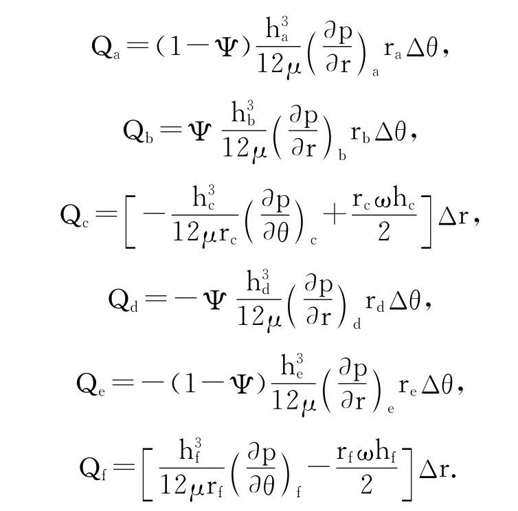
Note that here the mesh does not coincide with the radial groove pattern.The groove/ridge boundary divides the finite volume into two parts with their proportions in grooved and land regions beingΨand 1-Ψrespectively.For solving Eq.(15)in the presence of clearance discontinuity,the block-weight approach technique introduced by Kogure et al.[10]is implemented in this scheme.The technique involves averaging the mass flow across the discontinuity by appropriately estimating the mass flow contribution from both parts.
Then the mass flow terms in Eq.(15)can be written as:
Thus,the differential scheme ofpcan be deduced from equations above,by which the steady pressure distribution in the grooved thrust bearing is determined by iteratively solving Eq.(15)until the pressure reaches a steady value.The load capacity is obtained by integratingpnumerically on the lubrication region:

The ending condition of iteration is as follows:
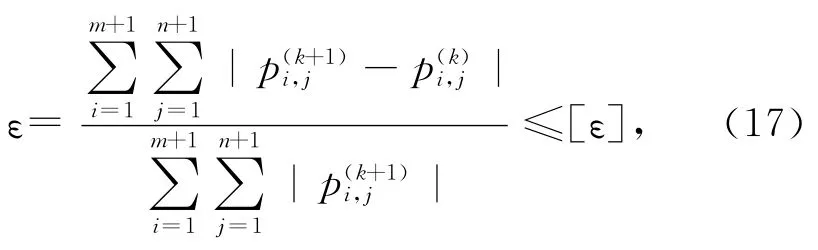
whereεis the iterative error from stepkto stepk+1,[ε]=1×10⁻⁶in this paper.
In order to achieve the steady value as quickly as possible,Eq.(15)is solved by line relaxation with a relaxation factor.The modified equation is as follows:

whereφis relaxation factor with range of 0<φ<2,pis the result of stepk,p~is iterative result from stepkto stepk+1,is the modified value ofp~.
4 Results and discussion
Conditions used in this section to obtain example results area=40mm,b=80mm,μ=0.1Pa·s,h0=1μm,hg=10μm, ω=16rad/s,α=60°andβ=120°.Thenumericalcalculational pressuredistributionofexampleisshownin Fig.3,inwhichtheareaisdividedinto40 (circumferential)by40 (radial)nodes.Anobvious effectofhydrodynamicexistsinthegroove/ridgeboundary,whichprovidesprimaryloadcapacityforthruststepbearings.
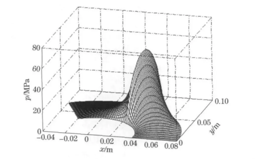
Fig.3 3 D pressure distribution for example
Analyticalsolutionandnumericalsolutionof anexamplearecomparedattwocrosssectionsin Fig.4aandFig.4b,i.e.,atθ=60°and atr=60mm.It is obviously that analytical solution and numerical solution are in good agreement in both radial and circumferential directions.
The mesh density of differential scheme affects the precision and speed of numerical calculation.Therefore,mesh density should be large enough to insure sufficient precision of results.Meanwhile,it should be as low as possible to increase the speed.The solutions as the function of mesh number are shown in Fig.5,in which we take the maximum pressure and load capacity of analytical solutions as the exact solution.Fig.5 indicates that the solutions present higher precision when mesh number exceeds 70×70.

Fig.4 2Dcross section of the pressure distribution

Fig.5 Variation of solutions as mesh number increases
Besides solutions precision discussed above,calculation speed is another important characteristic of differential scheme.For fast convergence,relaxation iteration is an effective method by adjusting relaxation factorφtoapropervalue.The computerprogramofdifferentialschemeinthispaperiswrittenwithMATLABandthecomputer CPUisIntelCore2.ThecalculationspeedversusφisshowninFig.6,wherethemeshnumberis100×100.Fig.6illustratesthatrelaxationfactorφevidentlyaffectsspeed.Furthermore,thefastestspeedof2.922sisobtainedwhenφequals1.94.Sincethespeedofanalyticalmethodsis muchfastercomparedwithnumericalmethod,it isnotdiscussedhere.

Fig.6 Variation of consumed time asφincreases
5 Conclusion
Inthispaper,thepressuredistributionand loadcapacityofradialgroovedthrustbearings havebeencalculatedwithanalyticalandnumericalmethods,respectively.Theblock-weightapproachisusedtodealwithnon-coincidenceof meshandradialgroovepattern.Theresultsof thetwomethodsareingoodagreement,which validatesthenumericalmodelproposedinthispaper.Thenumericalsolutionspresenthigherprecisionasmeshnumberexceeds70×70,andtherelaxationiterationofdifferentialschemepresents thefastestconvergencespeedwhenrelaxationfactoriscloseto1.94.Althoughanalyticalmethodis recognizedtobemoreexactandfaster,itismore difficulttodealwithcomplicatedgeometrycomparedwithnumericalmethod.
[1]Hamrock B J.Fundamentals of fluid film lubrication[M].New York:McGraw-Hill,1994.
[2]Chi Changqing. Hydromechanical lubrication[M].Beijing:National Defence Industry Press,1998:201-212.(in Chinese)
[3]Basu P.Analysis of a radial groove gas face seal[J].Tribology Transactions,1992,35(1):11-20.
[4]Song Pengyun.The liquid film characteristics of hydrodynamic mechanical seal with a spiral grooved face[D].Chengdu:Sichuan University,1999.(in Chinese)
[5]Song Pengyun,Chen Kuangmin,Dong Zongyu,et al.Numerical analysis of the pressure on the face of a radial groove mechanical seal for gas[J].Journal of Yunnan Polytechnic University,1999,15(3):1-6.(in Chinese)
[6]Song Pengyun,Huang Zecheng,Dong Zongyu,et al.An analysis of a radial groove mechanical seal for liquid[J].Journal of Sichuan Union University,1999,3(4):152-158.(in Chinese)
[7]Rahmani R,Shirvani A,Shirvani H.Analytical analysis and optimization of the Rayleigh step slider bearing[J].Tribol Int,2009,42(5):666-674.
[8]Liu S B,Chen W W,Hua D Y.Analytical solution to the hydrodynamic lubrication of fan-shaped thruststep bearings[J].ASME Journal of Tribology,2010,132(2):024504.
[9]Castelli V,Pirvics J.Review of numerical methods of gas bearing film analysis[J].ASME Journal of Lubrication Technology,1968,99(4):777-792.
[10]Kogure K,Fukui S,Mitsuya Y,et al.Design of negative pressure slider for magnetic recording disks[J].ASME Lubricated Technology,1983,105:496-502.
(Edited byCai Jianying)
 Journal of Beijing Institute of Technology2012年2期
- Journal of Beijing Institute of Technology的其它文章
- Artificial neural network modeling of mechanical properties of armor steel under complex loading conditions
- Optimization of the carrier tracking loop for GPS high dynamic receivers
- Vibration test of micro machined gyroscope based on high speed photography and SURF
- Experimental validation method of elastic thin rod model for simulating the motional cable harness
- Development of an occupant restraint system model and parametric study on equivalent crash pulse in vehicle frontal offset crash
- Distribution of driving trajectory of passenger car in highway horizontal curves