
Aerodynamics of flexible wing in bees’ hovering flight
2013-02-18 19:35YinDongfuZhangZhisheng
Yin Dongfu Zhang Zhisheng
(School of Mechanical Engineering, Southeast University, Nanjing 211189, China)
Humans have long been fascinated with flight through the air, and observations of nature fliers’ effortless defiance of gravity first inspired our dreams of taking to the air. Nonetheless, the early attempts to use flapping wings for propulsion failed; consequently, researchers paid more attention to fixed and rotary wings study and achieved great success in the past 100 years. However, traditional fixed-wing and rotary-wing flight began to fail as the flow dynamics entered a regime of insect-sized flights. The small scale air vehicles require different design ideas compared with the conventional ones. Then researchers turned to micro air vehicle(MAV)design by imitating insect flight,and looked forward to producing the micro flapping vehicle. But we have less-detailed understanding of flight mechanics so far. Previous studies show that the steady-state mechanism is inadequate to predict the aerodynamic lift and power requirements of small insects[1]. Some new techniques, such as the computational fluid dynamics (CFD) method and the unsteady theory, are required to reveal the mechanism of insect flight.
Previous studies on flapping flight have been undertaken from analytical, experimental and computational aspects. Sun et al.[2]investigated lift and power requirements for hovering flight in Drosophila virilis using the computational fluid dynamics method. Wang et al.[3]compared computational, experimental and quasi-steady forces in a generic hovering wing undergoing sinusoidal motion along a horizontal stroke plane. Liu[4]addressed an integrated and rigorous model for the simulation of insect flapping flight. However, the above models are based on idealized rigid wings and they do not consider the effect of the wings’ flexion during insect hovering flight. Insects use flapping wings to generate forces to balance their weight for hovering. Although insect wings are small and only account for 0.4% to 6.0% of body mass, they provide enough force for insect flight[5]. For the lift coefficient, the moderate wing flexibility leads to a 15% to 30% increase compared with the rigid wing[6]. To understand the mechanism of insect flight, Tanaka et al.[5,7]investigated wing flexibility on lift generation in hoverfly flight,and they pointed out that the flexible deformation should not be ignored.
In order to hovering, the flapping wings need to generate enough lift to support body weight in the vertical direction while maintaining a balance of aerodynamic forces and moments to stabilize the body, and need to consume more power compared with forward flight[8]. To provide a detailed view of the aerodynamics, control and energetics of the flexible wing in insect normal hovering flight, the aerodynamics of 2-dimensional flexible wing in bees’ hovering flight is studied. Understanding the mechanism of insect flight will help us to design micro-flapping flight aircraft.
1 Insect Flapping Flight Coordinate Systems
1.1 Four coordinate systems of flapping flight
To study the movement and deformation of the insect wings, four coordinate systems are defined as follows[4]:
1) A global system (o0x0y0z0) It is equivalent to an inertial system.
2) A body-fixed system (o1x1y1z1) Its origin is in the centroid of an insect, positivex1oriented the insect head, positivez1oriented the wing tip, positivey1oriented vertically upward. Fig.1(a) shows the angles of pitchθ, rollφ, and yawψwith respect to the body-fixed system.

4) A flexible wing-fixed system (o3x3y3z3) Its origin is at the centroid of the insect wings, positivex3oriented the leading edge, positivez3oriented the wing tip, positivey3oriented vertically upward.
The deformation of the insect wings generally includes chordwise and spanwise deflections[6], so the chordwise bending angleδand the spanwise bending angleγare defined. The wing near root and leading edge is simplified as rigid and the other part is flexible. Fig.1(c) shows the chordwise bending angleδand the spanwise bending angleγwith respect to the flexible body-fixed system.

Fig.1 Definition of insect flapping angles. (a) Body-fixed coordinate System; (b) Rigid wing-fixed coordinate system; (c) Flexible wing-fixed coordinate system
1.2 Transformation among four coordinate systems
The global system, the body-fixed system, the rigid wing-fixed system and the flexible wing-fixed system are used to reveal the insects’ position, gesture, the wings movement, and the wings deformation, respectively. To solve the general problem of insect flight, the coordinate system transformation is investigated. As shown in Fig.2(a), the transformation between the global system and the body-fixed system can be written as
(1)
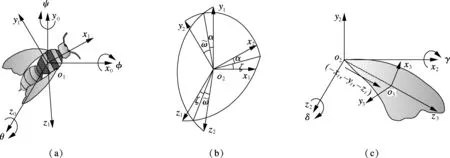
Fig.2 Transformation among four coordinate systems. (a) Transformation between global system and body-fixed system; (b) Transformation between body-fixed system and rigid wing-fixed system; (c) Transformation between rigid wing-fixed system and flexible wing-fixed system
As shown in Fig.2(b), the transformation between the body-fixed system and the rigid wing-fixed system can be written as
(2)
As shown in Fig.2(c), the transformation between the rigid wing-fixed system and the flexible wing-fixed system can be written as
(3)
whereK=(-xt,-yt,-zt), andKis a vector pointing fromo2too3.
1.3 Elliptic coordinate system
Although the above coordinate systems have the versatility, the elliptic coordinate system may be more helpful in 2-dimensional wing research. The computation of 2-dimensional insect hovering showed that a hovering motion can generate enough lift to support a typical insect weight[9]. As the cross-section of 2-dimensional wings is similar to an ellipse, wing chord can be simplified as an ellipse to facilitate the theoretical analysis and computation. The movement of the ellipse can be expressed in the elliptical coordinate. Fig.3 shows the established elliptic coordinate system.
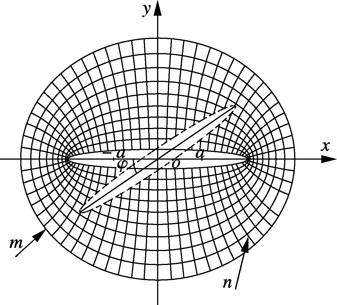
Fig.3 Established elliptic coordinate system
The conversion between the elliptic coordinate system and the Cartesian coordinate system is
x=acoshmcosn,y=asinhmsinn
(4)
where (-a, 0) and (a, 0) are two focuses of the ellipse; curves of constantmform ellipses, and curves of constantnform hyperbolae. The dashed ellipse represents the torsional wing chord andφis the torsion angle. The center of the ellipse coordinate system coincides with the center of the wings’ cross-section. The Navier-Stokes equation and the continuity equation expressed in the elliptic coordinate system have the following forms[10]:

(5)
whereuis the velocity field;wis the vorticity field;vis the velocity andSis the scaling factor. The mesh points are naturally clustered around the tips in the elliptical coordinate system. The radius of the computational boundary can be chosen to be 5 to 10 times the half-chord length[3]. While in the Cartesian coordinate system, this value is 20 to 50 times the half-chord length, so it can improve the computational accuracy and reduce the calculation complexity.
2 Computation Models and Methods
Fig.4(a) shows the forces and position of a rigid wing in the downstroke phase. During the hovering flight, the tip angle of the stroke plane is particularly small and the stroke plane is approximately horizontal. Hovering with a horizontal stroke plane is termed normal hovering[11]. The wing deformation of normal hovering flight can be represented as Fig.4(b). The thick line represents the wing chord and the filled circle represents the leading edge. In Fig.4,αis the angle of attack;φis the torsion angle;FLis the lift andFDis the drag. In hovering flight,FDis equal to thrust in the horizontal direction andFLis equal to the insect weight in the vertical direction. Insect wings have two forms of movements in one flapping cycle; the wing chord will distort at the beginning and end stage and translate at the middle stage in the stroke plane. The translational movement of a wing is governed byA(t)=A0/2 [cos(2πt/T)+1], and the rotational movement is governed bya(t)=π/[4(1-sin(2πt/T))][12]. Other wing flexure deformation parameters are set the same values as those in Ref.[13].
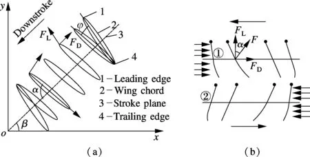
Fig.4 The generated forces and movement of wings. (a) Rigid wings in forward flight; (b) Flexible wings in hovering flight
The computational fluid dynamics problem is defined under the initial and boundary conditions. The solutions to the N-S equations require specific boundary conditions at the solid walls of dynamic flapping wings and the body as well as at the far-field outside boundary. The computational domain has a size of 50c×50c, wherecis the length of the wing chord. Extensive tests have been done to make sure that the domain is large enough to achieve satisfactory accuracy of the results. The outermost boundary of the computational domain is defined as the pressure-outlet wall. The wing boundary condition satisfiesvt=0=0 at the initial movement. The fluid velocity at fluid-wing boundaries is equal to that of the wing boundary. The no-slip condition for viscous fluids states that at the wing boundary, it satisfies the conditionvfluid=vwing.
The second-order up-wind numerical scheme and the SIMPLEC algorithm are used to solve 2-dimensional incompressible Navier-Stokes equations. At each time step, user-defined functions (UDFs) are used to control the wing’s motions and to obtain the aerodynamic performance. Dynamic mesh techniques are implemented by using the spring-based smoothing model and the local remeshing model.
The process to calculate the force, moment and power is as follows:
1) The pressure distribution of every face thread is obtained first, and then the pressure force is computed by looping over all face threads in the domain. The total force is the cumulative force of each face. In hovering flight, lift is the component of total force in the vertical direction,FL=Fcosα, and drag is the component of total force in the horizontal direction,FD=Fsinα(see Fig.4(b)).

3 Results and Discussion
The lift coefficient and the drag coefficient are defined as
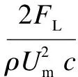
(6)
whereCL,CDare the lift coefficient and the drag coefficient, respectively;ρis the air density;Umis the average velocity of the wing chord;cis the wing chord length. The aerodynamic force acting on the wing is contributed by the pressure and viscous stress on the wing surface, and the total force is the sum of pressure force and viscous force. The lift and drag refer to the total lift and total drag. Fig.5 describes the computation results of lift coefficientCLand drag coefficientCD. Note that the lift coefficient and the drag coefficient are normalized and represented in the same diagram in order to compare the variation trend better. The results show thatCLandCDhave a similar variation trend with Wang’s research[3]. The small difference may be due to the parameter settings and wings flexible deformation. The wing is considered to be rigid in Wang’s research, while the wing is considered to be flexible in this paper.
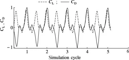
Fig.5 Computation results of lift and drag coefficients
The negative lift and drag means that the direction of lift and drag is opposite to definition. The large lift and drag peaks at the beginning and the end of the stroke can be explained by the superposition of the rapid translational acceleration, the fast pitching-up rotation of the wing and the wing’s rotation. The rotational circulation is caused by the Magnus effect, which makes the wing generate an upward force. This effect is similar to a rotational circulation mechanism[14]. Unlike the rigid wing’s results[15], the small peaks before large peaks in the first quarter-cycle can be explained by the convex flow effect. The wings are rigid in the translation process, so the drag has a steady increase at this stage. Then the wing has a flexible deformation (see Fig.4(b)①) before the rotation phase, and the wings area against airflow is reduced, so the drag has a slight decrease in this stage. The small peaks after large peaks in the second quarter-cycle can be explained by the concave flow effect, and the wings flexible deformation has not changed after the rotation phase (see Fig.4(b)②), so the wings area against airflow is increased and the drag has a slight increase an this stage. A similar theory can be used to explain the small drag peaks in the next half flapping cycle.
The average viscous force is probably 1/400 of the pressure force and the average viscous moment is only 1/775 of the pressure moment in our computation, as shown in Fig.6(a). The viscous force and moment can be ignored during the following insects’ normal hovering flight research. The total force and the total moment can be represented by the pressure force and the pressure moment, respectively. The average rotational power is probably 1/20 of the translational power, as shown in Fig.6(b), so insects will consume more energy for translational movement than for rotational movement. The positive power means that the flapping wings do work on fluid and the movement of wings needs to consume energy. The negative power means that the fluid produces work on flapping wings. This will help the wing form a convex flow shape and save the energy consumption of insect flight.
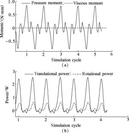
Fig.6 Aerodynamic moment changes and consumed power during several flapping cycles. (a) Comparison between pressure moment and viscous moment; (b) Comparison between translational power and rotational power
4 Conclusion
Four insect flapping flight coordinate systems are established to represent the bees’ position, attitude and wings deformation. Then the computation models of the 2-dimensional flexible wing are established, and the force, moment, and power changes are investigated. According to the computational results, the large lift and drag peaks at the beginning and end of the stroke can be explained by the superposition of the rapid translational acceleration, the fast pitching-up rotation and the Magnus effect. The small force and drag peaks can be explained by the convex flow effect and the concave flow effect. The viscous force, moment and rotational power are small and can be ignored. In the future research, a lot of work needs to be done to reveal the flight mechanism, such as numerical calculation of 3-dimensional flexible wing, quantitative analysis of force, moment and power. Understanding the mechanism of insect flight will be a great promotion of micro-flapping flight design and application.
[1]Ellington C P. The aerodynamics of hovering insect flight. VI. lift and power requirements[J].PhilosophicalTransactionsoftheRoyalSocietyofLondonSeriesB—BiologicalSciences, 1984,305(1122):145-181.
[2]Sun Mao, Tang Jian. Lift and power requirements of hovering flight in Drosophila virilis[J].TheJournalofExperimentalBiology, 2002,205(16): 2413-2427.
[3]Wang Z J, Birch J M, Dickinson M H. Unsteady forces and flows in low Reynolds number hovering flight: two-dimensional computations vs robotic wing experiments[J].TheJournalofExperimentalBiology, 2004,207(3):449-460.
[4]Liu Hao. Integrated modeling of insect flight: from morphology, kinematics to aerodynamics[J].JournalofComputationalPhysics, 2009,228(2): 439-459.
[5]Mountcastle A M, Combes S A. Wing flexibility enhances load-lifting capacity in bumblebees[J].ProceedingsoftheRoyalSocietyofSeriesB—BiologicalSciences, 2013,280(22): 1-8.
[6]Tian Fangbo, Luo Haoxiang, Song Jialei, et al. Force production and asymmetric deformation of a flexible flapping wing in forward flight[J].JournalofFluidsandStructures, 2013,36:149-161.
[7]Tanaka H, Whitney J P, Wood R J. Effect of flexural and torsional wing flexibility on lift generation in hoverfly flight[J].IntegrativeandComparativeBiology, 2011,51(1): 142-150.
[8]Fry S N, Sayaman R, Dickinson M H. The aerodynamics of hovering flight in Drosophila[J].TheJournalofExperimentalBiology, 2005,208(12):2303-2318.
[9]Wang Z J. Two dimensional mechanism for insect hovering[J].PhysicalReviewLetters, 2000,85(10): 2216-2219.
[10]Wang Z J. The role of drag in insect hovering[J].TheJournalofExperimentalBiology, 2004,207(23):4147-4155.
[11]Sun Mao. High-lift generation and power requirements of insect flight[J].FluidDynamicsResearch, 2005,37(1/2):21-39.
[12]Wang Z J. Computation of insect hovering[J].MathematicalMethodsintheAppliedSciences, 2001,24(17/18):1515-1521.
[13]Lu Guang, Yan Jingping, Zhang Zhisheng, et al. Dissection of a flexible wing’s performance for insect-inspired flapping-wing micro air vehicles[J].AdvancedRobotics, 2012,26(5/6): 409-435.
[14]Dickinson M H, Lehmann F O, Sane S. Wing rotation and the aerodynamic basis of insect flight[J].Science, 1999,284(5422):1954-1960.
[15]Zhang Genbao, Liu Yijun, Shi Wu, et al. Numerical simulation of two-dimensional flapping-wing MAVs[J].JournalofDonghuaUniversity:NaturalScience, 2011,37(2): 256-260. (in Chinese)
 Journal of Southeast University(English Edition)2013年4期
- Journal of Southeast University(English Edition)的其它文章
- Direct linear discriminant analysis based on column pivoting QR decomposition and economic SVD
- Construction of semisimple categoryover generalized Yetter-Drinfeld modules
- Exponential stabilization of distributed parameter switched systems under dwell time constraints
- Design and analysis of dual-mode structure repetitive control based hybrid current regulation scheme for active power filters
- Application of neural network merging model in dam deformation analysis
- Multiple solutions and fermion mass effect in QED3