
Distribution features, transport mechanism and destruction of cuttings bed in horizontal well*
2013-06-01 12:29ZHUXiaohua祝效华SUNChao孙超TONGHua童华
水动力学研究与进展 B辑 2013年4期
ZHU Xiao-hua (祝效华), SUN Chao (孙超), TONG Hua (童华)
School of Mechatronic Engineering, Southwest Petroleum University, Chengdu 610500, China, E-mail: zxhth113@163.com
Distribution features, transport mechanism and destruction of cuttings bed in horizontal well*
ZHU Xiao-hua (祝效华), SUN Chao (孙超), TONG Hua (童华)
School of Mechatronic Engineering, Southwest Petroleum University, Chengdu 610500, China, E-mail: zxhth113@163.com
(Received March 10, 2012, Revised December 10, 2012)
In an effort to develop methods of solving the issue of cuttings bed in horizontal wells, a 3-D transient model is established to simulate the distribution features and the transport mechanism of cuttings bed. The CFD calculation results show that the cuttings at the cross-sectional area of the mutation location such as the drilling pipe connector would easily settle down to build up a cuttings bed and the transport performance of the cuttings in a horizontal well can only be improved to some extent by adjusting the working parameters without using any destruction tools for the cuttings bed, thus the issue of a cuttings bed can not be solved in general. Accordingly, a new approach to effectively prevent and actively destroy the cuttings bed by using the Cuttings Bed Impeller (CBI) is proposed, the sensitivity analysis of which is conducted to determine the optimal structural parameters and the best matched working parameters from a perspective of the wellbore cleaning. Results show that the use of the CBI produces a number of benefits, including the reduced drill string torque to avoid the stuck pipe incidents with corresponding improvement in hole quality, a shorter trip time, and less wear on the drill string, the top drive and the casing. This research offers theoretical guidelines for the design of destruction tools for the cuttings bed and for the wellbore cleaning control in the horizontal drilling.
cuttings bed, Cuttings Bed Impeller (CBI), sensitivity analysis, stuck pipe
Introduction
Due to the severe deficiency in prospective hydrocarbon resources and the increasing difficulty in the exploratory development of oil and gas fields, the drilling technology calls for advancement into a new level to cost-effectively deal with the increasingly complex exploratory situation in China. The drilling technology of the horizontal well has been developed rapidly since the 1980s, and makes a great contribution in enhancing the recovery of oil because of its high well production and excellent overall efficiency of the oilfield development[1]. The drilling technology of the horizontal well was applied in Well Yun 2-Ping 1#, for example, which saved 4×10⁷of funds and reduced the cost of oil per ton by 7.28%[2]. However, the wellbore cleaning control of the horizontal well is one of three major problems in the horizontal drilling technology. In the process of the horizontal drilling, a cuttings bed might easily build up in a lower wall due to the effect of gravity, and the main potential hazards include: (1) the wellbore cleaning control is extremely difficult and it is adverse to the Rate Of Penetration (ROP), (2) the friction and the torque increase rapidly, which creates a risk of pipe stuck accidents. In 2000, the statistics from Anhui oil exploration and development company shows that the pipe stuck accidents in the horizontal well take up 3.43%-11.67% of the total completion time, and an economical loss of millions or even more dollars had been brought about under the condition of poor wellbore cleaning[3-5].
Although the cuttings transport was studied in recent years, the potential problems of cuttings in a horizontal well are not ultimately solved, especially, it still lacks a good understanding about the distribution features and the transport mechanism of the cuttings bed in a horizontal well.
So far, many positive measures like adjusting working parameters are adopted in the oilfield to solve the problems of the cuttings bed in the horizontal well. However, our numerical simulation results suggest that the transport performance of the cuttings in a horizontal wellbore can only be improved to some extent by adjusting working parameters without using any tools to destroy the cuttings bedl, which can not fundamentally solve the issue of the cuttings bed. In view of this, a new approach to effectively prevent and actively destroy the cuttings bed by using the destruction tool (Cuttings Bed Impeller (CBI)) is proposed, and a sensitivity analysis is made to determine the optimal structural parameters and the best matched working parameters in the context of the wellbore cleaning. Finally, numerical results are compared with the field test results of the CBI in Well J-NP12-168 of Jidong Oilfield, which shows that the CBI is an attractive and efficient method for solving the issue of the cuttings bed in the horizontal well.
In this study, the commercial CFD packages including Gambit 2.2.30 and Fluent 6.2.16, are used to generate the mesh and then to solve the governing equations with the finite volume method, and the renormalization-group (RNG) method is used to solve the Navier-Stokes equations with the conventional SIMPLEC algorithm for the continuous flow.
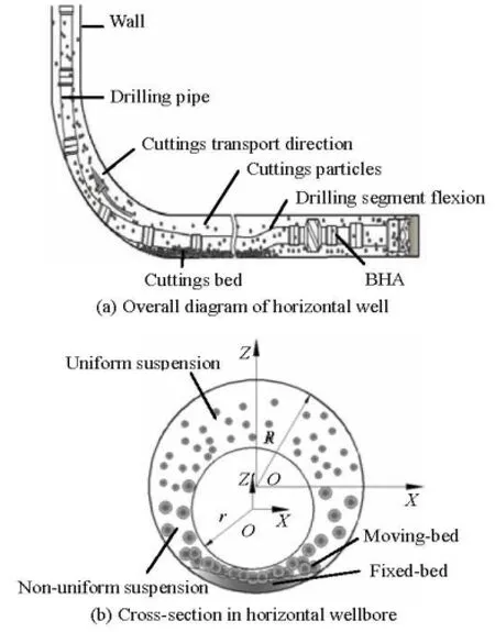
Fig.1 Cuttings transport patterns in horizontal wellbore
1. Analysis model
1.1 Cuttings transport patterns As was shown[6,7], the annular between the wellbore and the drilling pipe is with a eccentricity in the horizontal well because of the gravity in the drilling pipe, which creates a poor transport environment for the returned cuttings. Figure 1 shows four cuttings transport patterns in an eccentric wellbore of the horizontal well: the suspension types including the uniform suspension type and the non-uniform suspension type, the moving bed type and the fixed bed type.
1.2 Two-phase flow model
We will explain why the RNG -kε model is used for the numerical calculations in this paper.
The commercial code Fluent 6.2.16 mainly provides the following choices of -kε turbulence models: (1) the standard -kε model, (2) the RNG k-ε model, (3) the realizable k-ε model. Different k-ε models have different characteristics. For instance, the standard -kε model, proposed by Wilcox (1998), is the best choice for the isotropic turbulent motion without any rotational flow or the complex flow with associated secondary flows, which enjoys high stability, efficiency, and computational accuracy. The realizable -kε model, proposed by Shih et al. (1995), is mostly used in the simulation of a shear flow or a free flow and the RNG -kε model, which is derived by using a rigorous statistical technique and is proposed by Yakhot and Orzag (1986), is commonly used to deal with a distorted flow or a rotational flow, and is advantageous in dealing with high strain rate fluid flows.
Considering the research objectives in this paper and the fact that the returned drilling fluid with cuttings in the horizontal well is highly irregular high-Reynolds-number turbulence flow, the RNG -kε model should be the most appropriate method to solve the liquid-solid two-phase flow in this study.
1.2.1 Assumptions
(1) The mixing flow is in a 3-D and unsteady state.
(2) The drilling fluid is isothermal and Newtonian.
(3) Particles are simulated as balls, and their deformation and velocity slip during collisions are neglected to simplify the computation.
Based on the above assumptions and taking into account the influence of the volume fraction of the drilling fluid and the drag force between the fluidphase and the discrete-phase in the volume averaged Navier-Stokes equation, the governing equations that include those of continuity, momentum, turbulent kinetic energy ()k, turbulence dissipation rate ()ε and particles transport are expressed as follows[8-12].

Table 1 The calculation values of turbulence equation constants

Table 2 Input values for CFD models
1.2.2 Continuity and momentum equations
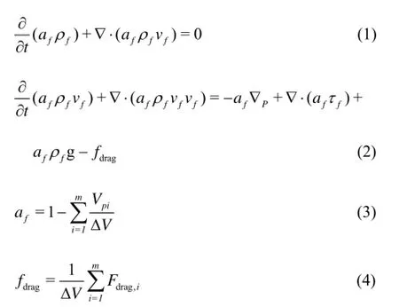
wherefρ,fa andfv represent the density, the volume fraction, and the velocity of the drilling fluid, respectively. Andfτ,dragf, g,piV, VΔ,dragF and m represent the drilling fluid shear stress, the volumetric fluid-particle interaction force, the gravitational acceleration, the volume of particles i inside this cell, the volume of a computational cell, the drilling fluid drag force on an individual particle, and the number of particles in the cell, respectively.
1.2.3 -kε equations of RNG -kε model
whereeffμ, k and ε represent the equivalent viscosity of the drilling fluid, the turbulent kinetic energy and the turbulence dissipation rate, respectively, Ek, Eband YMrepresent the generation of the turbulence kinetic energy due to the mean velocity gradients, the generation of the turbulence kinetic energy due to the buoyancy and the contribution of the fluctuating dilatation in the compressible turbulence to the overall dissipation rate, respectively, Skand Sεare the userdefined source terms, and αkand αεare the inverse effective Prandt1 numbers for k and ε, respectively.
According to the Launder’s recommended values and the experimental verification, the values of the RNG k-ε model parameters in subsequent calculations are listed in Table 1.
1.2.4 Particles transport equation
where ρp, mpand vpare the density, the mass and the velocity of the particle i, respectively, dvp/dt is the inertia force of the cuttings, FD(vf-vp) is the cuttings’ per unit mass drag force, and g(ρp-ρf)/ ρpis the cuttings’ gravity, F represents other forces.
1.2.5 Simulation conditions
In this study, the fluid-phase is the drilling fluid, and the discrete-phase is the particles of the cuttings. The simulation model has one inlet and one outlet for the drilling fluid and the cuttings, the positive direction of Z-axis is the direction of the gravitational field, and numerical computations for 2 000 m’s deep well was conducted under the conditions with the annular eccentricity ()ζ of 0.1, the inlet volume fraction of cuttings (Voverall) of 0.3% and the operating pressure (Pannular) of 2×10⁷Pa. The initial condition isa flow field with 10% turbulence intensity along with the mean flow velocity of 1.4 (vp=vf=1.4 m/s, according to the third assumptions) in the streamwise direction, and the SIMPLE algorithm is used for pressure-velocity coupling in calculations. The input values for the CFD models are listed in Table 2.
Fig.2 The schematic diagram of the calculation model of the drilling pipe

Fig.3 The grids for the numerical simulation model
1.3 Research objects and the grids
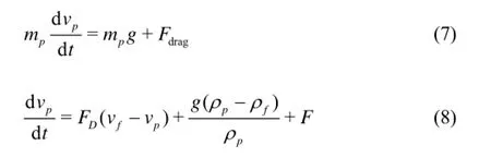
For describing the distribution features of the cuttings bed, the numerical calculations of the transport performance of the cuttings in an eccentric annular are carried out by adjusting the working parameters (the flow of the drilling fluid, the rotational speed of the drilling pipe and the viscosity of the drilling fluid) and taking four surfaces as research objects (the numerical simulations are carried out for two API drilling pipes, each of 9 m in length ): (1) the surface of the drilling pipe connector facing the cuttings (B, D), (2) the surface of the drilling pipe connector at the back of the cuttings (A, C), (3) the surface of the drilling pipe body, (4) the surface of the drilling pipe connector, as shown in Figs.2(a) and 2(b). As shown in Figs.2(a) and 2(c), the end of drilling pipe connector locates at Y=0m , and H represents the thickness of the cuttings bed in the lower annular. Note, we will use“pipe”, “connector” as simple replacements of the drilling pipe and the drilling pipe connector, respectively, in the discussions below.
In this paper, the grid method is employed to save the computer resource and the computation time. Thus, a composite grid (with the unstructured grid and the structured grid) is generated for above calculation models of the pipe by the Gambit 2.2.30, where the models are mainly meshed by using hexahedral grids rather than tetrahedral grids because of its high quality, high convergence rate and smaller discretization error. However, due to the division limitation of the grid generation, one has to use tetrahedral grids instead of hexahedral grids in some complex computational domains like the annular area of the connector which is partitioned by tetrahedral grids, and the rest parts of the numerical model are meshed by hexahedral grids, as shown in Fig.3. A total of 743 881 grids are generated for the whole domain: including (1) the annular domain around the body, (2) the annular domain around the connector, (3) the interface domain of the body and connector.
1.4 Influences of working parameters on transport performance of cuttings
In order to study the influence of the flow of the drilling fluid on the transport performance of the cuttings in a horizontal well, numerical calculations are carried out for the flow of the drilling fluid (qf) of 10 L/s-30 L/s. It is shown in Fig.4(a) that: (1) the volume fraction of the cuttings assumes the maximum value near the surface of the connector facing to the cuttings and the minimum value near the surface of the connector at the back of the cuttings, varying from small to large along with each drilling pipe, (2) the volume fraction of the cuttings decreases significantly when the flow of the drilling fluid (qf) increases, in-dicating that a large flow of the drilling fluid is recommended in the well-section such as the horizontal well-section where the cuttings bed is easily to build up.
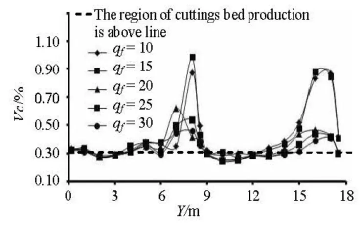
Fig.4(a) The volume fraction curve of cuttings for varius flows
Under the condition of qf=30 L/s, the numerical calculations are carried out with the rotational speeds of the pipe ()ω of 1 r/s-3 r/s. It is shown in Fig.4(b) that the rotational speed of the pipe has a negligible impact on the volume fraction of the cuttings.

Fig.4(b) The volume fraction curve of cuttings for various rotational speeds of the drilling pipe
Under the conditions of qf=30 L/s and ω= 1 r/s, the numerical simulations are conducted for the viscosity of the drilling fluid (μf) of 0.001 Pa·s-0.05 Pa·s. It is shown in Fig.4(c) that too large (μf>0.01Pa⋅s) or too small (μf<0.005Pa⋅s) viscosity of the drilling fluid is not conducive to the cuttings transportation in a horizontal well.

Fig.4(c) The volume fraction curve of cuttings for various viscosities
1.5 Analysis of distribution features and transport mechanism of cuttings bed
As the initial condition mentioned in Section 1.2.5, the inlet volume fraction of the cuttings (Voverall) is set as 0.3%, and it can be expected that the cuttings bed will built up while the volume fraction of the cuttings on the Y-direction cross-section is above 0.3%. From Fig.4 it is seen that the region of the cuttings bed production is mainly at the drilling pipe connector.

Fig.5 X-direction volume distribution slice of cuttings near connector at different moments
Based on the optimal working parameters as in the previous discussion, numerical calculations are carried out for the transport performance of the cut-tings near the connector. Figure 5 show the X-direction volume distributions of the cuttings near the connector at different moments in the horizontal well, and it is indicated that the cuttings are basically carried by the drilling fluid in the lower annular of the horizontal wellbore, and only a small amount of cuttings can be found in the upper annular closer to the upper surface of the pipe. With the passage of time, the volume fraction of the cuttings in the lower annular increases significantly, indicating that the cuttings begins to settle down and to build up a fixed cuttings bed, with its most obvious region at the connector.
It is shown that the cuttings at certain cross-sectional areas such as the connector can easily settle down to build up a fixed cuttings bed, especially, under some conditions: (1) a small flow of the drilling fluid, (2) a large viscosity of the drilling fluid, (3) a low-speed flowing of the drilling fluid. Above all, the transport performance of the cuttings in the horizontal wellbore can only be improved to some extent by adjusting working parameters without using any destruction tools for the cuttings bed, which can not fundamentally solve the issue of the cuttings bed.

Fig.6 Structure and working mechanism of CBI
2. Cuttings bed impeller

Fig.7 Finite element simulation model of CBI and flow field velocity vectors

Fig.8 Schematic diagram of the cuttings transport on the surface of CBI and contour line of drilling fluid near the connector in eccentric annular before and after using CBI
Inanefforttoeffectivelysolveorsubstantiallyalleviate the issue of the cuttings bed in a horizontal well, a new method of using CBI is proposed, which is designed with a double destruction methodology of hydraulics and mechanics. The schematic diagram of the structure and the working mechanism of the CBI are shown in Fig.6.
The CBI is a simple, one-piece string component designed for use in applications where the hole cleaning is critical. Fig.6(a) shows that the CBI is mainly composed of the body 1,the transition slope diversion 2, the neck 3, the export diversion slope 4, the spiralshaped impeller 5, the spiral-shaped groove 6 and the inlet diversion slope 7. The hydraulics and mechanics principles of the CBI are shown in Figs.6(b) and 6(c): the CBI’s spiral-shaped impeller not only can break the returned cuttings groups into small cuttings particles but also agitate the cuttings to prevent them to build up and facilitate their removal, and in addition, the rotation of the spiral-shaped groove can carry the cuttings bed which has built up in the lower wall to the high-speed zone of the upper annular. This results in a reduced drill string torque and erosion and reduces the likelihood of the pipe being stuck.
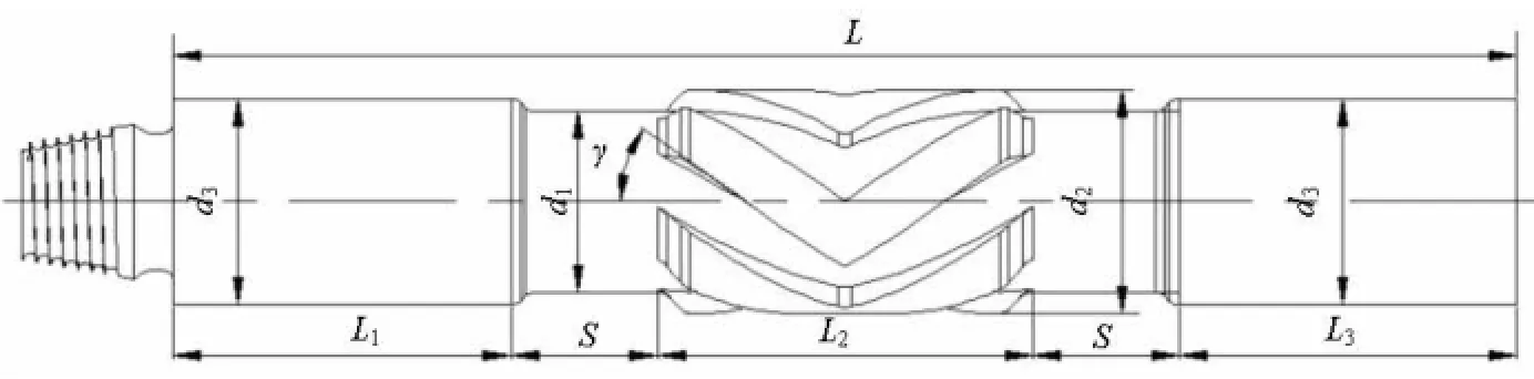
Fig.9 Schematic diagram of CBI’s structure design
3. Working characteristics analysis of CBI
In an effort to explore the engineering value in the use of the CBI, this paper adopts a 3-D unsteadystate model to simulate the cuttings transport with the CBI being installed in the horizontal wellbore, and the results are compared with those of the pipe of the same specification.
As is mentioned in Section 1.3, the parts of the complex computational domain including the annular areas of the connector and the CBI are partitioned by tetrahedral grids, and the rest parts of the numerical model are meshed by hexahedral grids. The grids of the annular domain around the CBI are shown in Fig.7(a). Figs.7(b) and 7(c) show the flow field velocity vectors of the pipe and the CBI, respectively. Fig.7(d) shows the flow field velocity vectors at the time of 5 s in the numerical calculation.
Figures 7(b), 7(c) and 7(d) show that as compared with the pipe of the same specification, obviously stronger turbulent flow can be formed for the drilling fluid around the spiral-shaped groove, which can effectively prevent the building up of the cuttings bed in the horizontal wellbore, and the velocity of the drilling fluid in the zone of the upper wall increases with the use of the CBI, which is conducive to improve the transport performance of the cuttings in an eccentric annular. In addition, the low-speed blue vector lines are replaced by the high-speed yellow lines at the moment of 5 s of the numerical calculation, indicating that the horizontal wellbore can be kept clean after using CBI for a while.
According to the simulation results, a schematic diagram of the cuttings transport on the surface of the CBI and the velocity contour lines of the cuttings near the connector in the eccentric annular before and after using the CBI are shown in Fig.8, respectively. Comparing Fig.8(b) with 8(c), the velocity of the drilling fluid in the upper annular changes from 2.18 m/s to 1.96 m/s before using the CBI while the value in the lower annular changes from 0.64 m/s to 1.09 m/s after using the CBI, which reduces the value difference between the high-speed zone in the suspension-layer and the low-speed zone in the fixed-layer.
4. Structural and working parameters optimization
To further explore the potential functions of the CBI, it is desirable to examine the influences of the structural parameters and the working parameters on the performance of the CBI. After repeated numerical calculations on the properties of the cuttings bed after using the CBI, the optimal structural parameters and the best matched working parameters of the CBI are determined.
Figure 9 shows a schematic diagram of the 2-D structure design of the CBI. A CBI of Φ 0.185 m in the specification (d2=0.185m)is selected as the research object in a commonly used wellbore (Φ 0.2159 m). The fixed parameters include the total length of the CBI ()L, the axial lengths of the body (1L and3L), the diameter of the neck1()d, the diameter of the spiral-shaped impeller2()d and the diameter of the body3()d. The variable parameters include the axial length of the spiral-shaped impeller2()L, the tilt angle ()γ, the neck length ()s and the number ofspiral-shaped impellers ()n.
4.1 Structural parameter optimization
According to the design principles “the spiralshaped impeller should be centralized within 360o”, the axial length of the spiral-shaped impeller 2()L, the diameter of the spiral-shaped impeller2()d, the number of the spiral-shaped impellers ()n and the tilt angle ()γ should satisfy the following relationship,
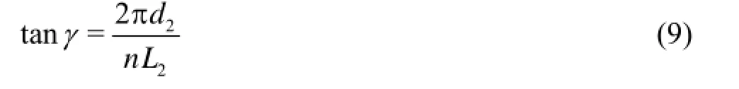
Once the tilt angle ()γ, the diameter of the spiral-shaped impeller2()d and the number of the spiral-shaped impellers ()n are selected, the axial length of the spiral-shaped impeller 2()L could be determined as well.
As was mentioned in literature[13-15], the turbulent intensity of the fluid can be simply characterized by its tangential velocity. In addition, it is evident that the turbulent intensities of the fluid and the cuttings represent the capacity of the CBI to prevent the building up of the cuttings bed. Thus, the subsequent numerical calculations are conducted by using the following evaluation criteria for the tangential velocity of the drilling fluid (τf) and the tangential velocity of the cuttings (τc).

Fig.10 Influences of the tilt angle on the performance of CBI
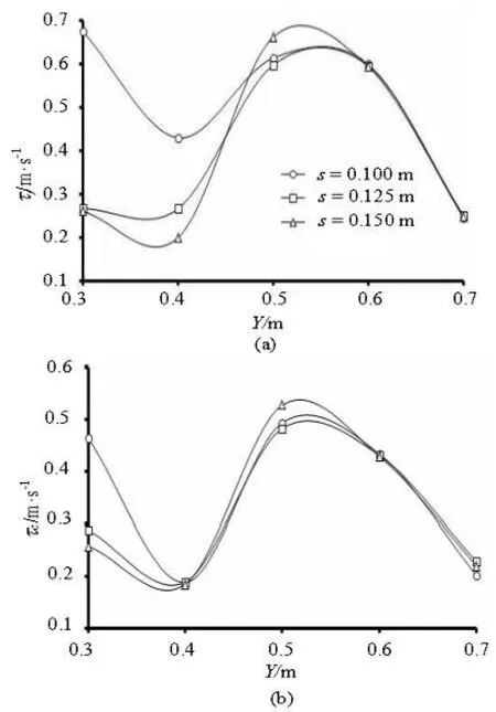
Fig.11 Influences of neck length on performance of CBI
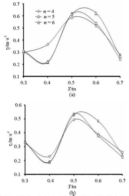
Fig.12 Influences of neck length on the performance of CBI
4.1.1 Influences of the tilt angle on the performance of the CBI
Under the initial conditions of =0.1ms and =n5, numerical calculations are conducted by changing the tilt angle ()γ in the range of 0o-30o, as shown in Fig.10 (Note: =1.2mL, =0mY is at the end of the CBI body). The numerical results show that increasing the value of the tilt angle is conducive to increase the turbulence intensity of the drilling fluid and the cuttings, and the tilt angle of a large value such as 30ois advisable in the horizontal wellbore where it is easy to build a cuttings bed.

Table 3 Numerical results for working parameters

Fig.13 Influence of working parameters on performance of CBI
4.1.2 Influences of the neck length on the performance of the CBI
Based on the previous discussion, numerical calculations are carried out for cases with the neck length ()s in the range of 0.1 m-0.15 m and the tilt angle is set to be a constant of 30o, as shown in Fig.11 (Note: L=1.2m , Y=0m is at the end of the CBI body). And the numerical results show that increasing the neck length has a negligible influence on the turbulent intensity of the drilling fluid and cuttings near the spiral-shaped impeller, but a significantly reduction around the neck. Consequently, the neck length is determined to be a small value such as 0.1 m.
4.1.3 Influences of number of spiral-shaped impellers on the performance of CBI
Based on the above discussions, numerical calculations are carried out with various numbers of spiralshaped impellers ()n of 4-6 where the tilt angle and the neck length are set to be constants of 30oand 0.1 m, respectively, as shown in Fig.12 (Note: =L 1.2 m, =0mY is at the end of the CBI body). The numerical results show that increasing the number of spiral-shaped impellers can increase a little the turbulent intensity of the drilling fluid and the cuttings around the spiral-shaped impeller, but lead to a significant reduction around the neck. Consequently, the number of spiral-shaped impellers should be selected to be 5 under the permitted conditions of the processing technology.
4.2 Optimization of the working parameters
Based on the numerical results in Section 1.4, the influences of working parameters on the performance of the CBI are studied with different flows of the drilling fluid (qf), viscosities of the drilling fluid (μf) and rotational speeds of the CBI (ωCBI). The numerical results for working parameters are shown in Table 3. In our research, two evaluation criteria are used to assess the influence of working parameters on the performance of the CBI: the volume fraction of the cuttings (Vc) and the velocity of the cuttings in different transport layers (vc).
Figure 13(a) shows the volume fraction curve of the cuttings related to the flow of the drilling fluid (qf), and it is indicated that increasing the flow of the drilling fluid is conducive to enlarge the volume fraction of the cuttings in the suspension layer and the moving bed layer, by which the ability of the CBI to prevent the bulding up of the cuttings bed in the horizontal wellbore can be improved in a moderate extent. Consequently, a large flow of the drilling fluid such as 30 L/s should be advisable if a specific drilling fluid is chosen.
Figure 13(b) shows the velocity curve of the cuttings related to the viscosity of the drilling fluid (μf), and it is indicated that the velocity of the cuttings in different transport layers after using the CBI increases with the increase of the viscosity of the drilling fluid when μf≤0.08Pa⋅s , in which the range of 0.001 Pa·s-0.01 Pa·s is the fastest growing region. Consequently, the viscosity of the drilling fluid of 0.01 Pa·s is a good choice for the CBI carrying the cuttings in a horizontal wellbore.
A comparison of two drilling pipes connected in front of and behind the CBI shows that the volume fraction of the cuttings in the lower wall behind the CBI is significantly lower than that in front of the CBI, as indicated in Fig.13(c). Fig.13(d) shows the velocity contour of the cuttings related toCBIω, and it is indicated that increasing rotational speed of the CBI can significantly increase the velocity of the cuttings transport in each layer. Accordingly, a large rotational speed of CBI such as 2 r/s-3 r/s should be advisable if a conventional flow of the drilling fluid such as 10 L/s-20 L/s is used.
Above all, the approaches of enhancing CBI’s efficiency of preventing the suspended cuttings from settling down to build up a fixed cuttings bed are established.
5. Case analysis and application of CBI
The prototype of the CBI is shown in Fig.14(a), which is also included in the drill string to facilitate the hole cleaning and maintain the hole quality in Well J-NP12-168 of Jidong oilfield. All the data mentioned below came from the actual case of the well, and the basic parameters are: the total well depth of 5 040 m, the vertical depth ()P of 2 547.36 m, the horizontal displacement of 3 802.32 m, the maximum deviation angle of 72.4o, the KCL forming-film sealing drilling fluid with density of 1240 Kg/m3. The schematic diagram of the drilling working conditions with the CBI and the field test results of the CBI are shown in Figs.14(b) and 14(c). From a comparison with the data prior to running the tools, it is shown that:
(1) A 20%-25% reduction in torque ()M after running the CBI.
(2) A 5%-10% growth in the ROP after running the CBI.
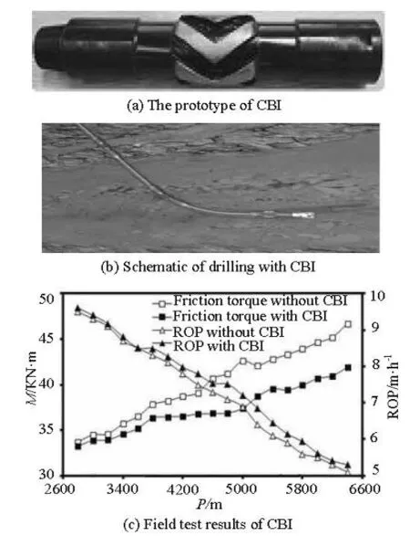
Fig.14 Field application of CBI
Based on the field test results of the CBI, it can be concluded that the method of using CBI is conducive to reduce the construction and completion cycle of the well. It becomes easier lifting or putting down the drill and the casing and making electrical measurements in the horizontal well-section of the well tested, in the process of which a primary benefit is the elimination of stuck pipe incidents with a corresponding improvement in the hole quality.
6. Conclusions
The following main conclusions can be drawn from this theoretical and experimental study:
In the horizontal well drilling, the cuttings at thecross-sectional area mutation location such as the connector can easily settle down to build up a fixed cuttings bed, especially under some certain conditions: (1) a small flow of the drilling fluid, (2) a large viscosity of the drilling fluid, (3) a low-speed flowing of the drilling fluid, and the transport performance of the cuttings in a horizontal wellbore can only be improved to some extent by adjusting working parameters without using any destruction tools for the cuttings bed, which can not fundamentally solve the issue of the cuttings bed.
A new approach to effectively prevent and actively destruct the cuttings bed by using the destruction tool (CBI) is proposed, the sensitivity analysis of which is conducted to determine the optimal structural parameters and the best matched working parameters from a perspective of the wellbore cleaning. The studies performed here show that the tilt angle of 30o, the neck length of 0.1 m and the number of spiral-shaped impellers of 5 are optimal for the CBI to effectively prevent the building up of the cuttings bed in the horizontal wellbore. The studies of the influence of working parameters on the performance of the CBI show that the approaches of enhancing CBI’s efficiency of preventing the suspended cuttings from settling down to build up a fixed cuttings bed include: (1) to set up a large flow of the drilling fluid such as 30 L/s if a specific drilling fluid is chosen, (2) to set up a large rotational speed of the CBI such as 2 r/s-3 r/s if a conventional flow of the drilling fluid such as 10 L/s-20 L/s is used, (3) the viscosity of the drilling fluid of 0.01 Pa·s is a good choice for the CBI carrying the cuttings in a horizontal wellbore.
The field tests show that the use of the CBI in Well J-NP12-168 of Jidong oilfield produces a number of benefits, including a reduced drill string torque, reducing the stuck pipe incidents with the corresponding improvement in the hole quality, a shorter trip time (no pumping out), and less wear on the drill string, the top drive and the casing.
In the present study, however, several assumptions are made, which should be kept in mind in the interpretation of the results. For instance, the drilling fluid in the eccentric annular is considered to be isothermal to simplify the computation. The particle deformation during collisions and the velocity slip between the fluid-phase and the discrete-phase are not considered in the RNG -kε model. Subsequent studies should overcome these weaknesses.
[1] WANG Rui-he, CHENG Rong-chao and WANG Haige et al. Numerical simulation of transient cuttings transport with foam fluid in horizontal wellbore[J]. Journal of Hydrodynamics, 2009, 21(4): 437-444.
[2] WANG Zhi-ming, ZHANG Zheng. A two-layer timedependent model for cuttings transport in extended reach horizontal wells[J]. Journal of Hydrodynamics, Ser. A, 2004, 19(5): 676-681(in Chinese).
[3] THE DEPARTMENT OF ENGINEERING TECHNOLOGY AND MARKET OF CHINA NATIONAL PETROLEUM CORPORATION. Exploration and production company of PetroChina company limited horizontal well technology seminar proceedings[M]. Beijing: Petroleum Industry Press, 2008(in Chinese).
[4] AZIZ T. N., RAIFORD J. P. and KHAN A. A. Numerical simulation of turbulent jets[J]. Engineering Applications of Computational Fluid Mechanics, 2008, 2(2): 234-243.
[5] SAINTPERE S., MARCILLAT Y. and BRUNI F. et al. Hole cleaning capabilities of drilling foams compared to conventional fluids[C]. SPE 63049. Dallas, Texas, USA, 2000.
[6] ZOU L., PATEL M. H. and HAN G. A new computer package for simulating cuttings transport and predicting hole cleaning in deviated and horizontal wells[C]. SPE 64646. Beijing, China, 2000.
[7] INDRA G., RUDI R. Determining cutting transport parameter in a horizontal coiled tubing underbalanced drilling operation[C]. SPE 101937. Melboume, Australia, 2002.
[8] LIOUMBAS J. S., KOLIMENOS C. and PARAS S. V. Liquid layer characteristics in gas-liquid flow in slightly inclined pipes[J]. Chemical Engineering Science, 2009, 64(24): 5162-5172.
[9] LONG Zhi-hui, WANG Zhi-ming and GUO Xiao-le. Transport mechanism of cuttings in annulus during deviated and horizontal drilling[J]. Journal of China University of Petroleum, (Edition of Natural Science), 2005, 29(5): 42-45(in Chinese).
[10] CHO H., SHAH S. N. and OSISANYA S. O. A Three segment hydraulic model for cuttings transport in coiled tubing horizontal and deviated drilling[J]. Journal of Canadian Petroleum Technology, 2002, 41(6): 32-39.
[11] QUAMRUL H. M., SIAMACK A. S. and BRENTON S. M. Prediction of solid particle erosive wear of elbows in multiphase annular flow-model development and experiment validations[J]. Journal of Energy Resources Technology, 2008, 130(2): 1-10.
[12] ZHU X. H., JING J. and TONG H. Causes and conditions for reamer blade balling during hole enlargement while drilling[J]. Engineering Applications of Computational Fluid Mechanics, 2012, 6(1): 87-99.
[13] NIU Y. Y., LIN Y. C. and CHANG C. H. A further work on multi-phase two-fluid approach for compressible multi-phase flows[J]. International Journal for Numerical Methods in Fluids, 2008, 58(8): 879-896.
[14] GRADECK M., LEBOUCHÉ M. Two-phase gas-liquid flow in horizontal corrugated channels[J]. International Journal of Multiphase Flow, 2000, 26(3): 435-443.
[15] BALASUBRAMANYAM M. S., BAZAROV V. G. and CHEN C. P. Numerical design investigation of a hydromechanical pulsator for rocket motor injector dynamics research[J]. Engineering Applications of Computational Fluid Mechanics, 2010, 4(2): 314-325.
10.1016/S1001-6058(11)60405-9
* Project supported by the National Natural Science Foundation of China (Grant Nos. 51222406, 51004082), the New Century Excellent Talents in University of China (Grant No. NCET-12-1061) and the Scientific Research Innovation Team Project of Sichuan colleges and universities (Grant No. 12TD007).
Biography: ZHU Xiao-hua (1978-), Male, Ph. D., Professor

- 水动力学研究与进展 B辑的其它文章
- Ship bow waves*
- Progress in numerical simulation of cavitating water jets*
- Three-dimensional large eddy simulation and vorticity analysis of unsteady cavitating flow around a twisted hydrofoil*
- Numerical simulation of shallow-water flooding using a two-dimensional finite volume model*
- Dynamical analysis of high-pressure supercritical carbon dioxide jet in well drilling*
- Micropaticle transport and deposition from electrokinetic microflow in a 90obend*