
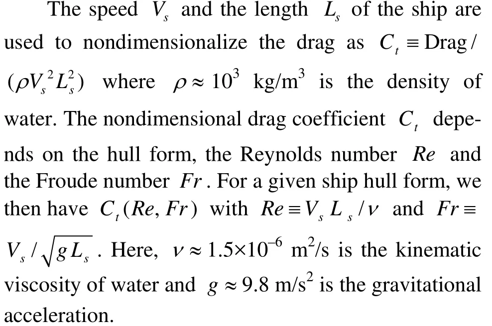
Practical evaluation of the drag of a ship for design and optimization*
2013-06-01 12:29YANGChiHUANGFuxin
水动力学研究与进展 B辑 2013年5期
YANG Chi, HUANG Fuxin
Center for Computational Fluid Dynamics, George Mason University, Fairfax, VA, USA,
E-mail: cyang@gmu.edu
NOBLESSE Francis
State Key Laboratory of Ocean Engineering and School of Naval Architecture, Ocean and Civil Engineering, Shanghai Jiao Tong University, Shanghai 200240, China
(Received June 8, 2013, Revised October 10, 2013)
Practical evaluation of the drag of a ship for design and optimization*
YANG Chi, HUANG Fuxin
Center for Computational Fluid Dynamics, George Mason University, Fairfax, VA, USA,
E-mail: cyang@gmu.edu
NOBLESSE Francis
State Key Laboratory of Ocean Engineering and School of Naval Architecture, Ocean and Civil Engineering, Shanghai Jiao Tong University, Shanghai 200240, China
(Received June 8, 2013, Revised October 10, 2013)
We consider two major components of the drag of a ship, the “friction drag” and the “wave drag”, that are related to viscous friction at the hull surface and wavemaking, and mostly depend on the Reynolds number and the Froude number, respectively. We also consider the influence of sinkage and trim, viscosity, and nonlinearities on the drag. The sum of the friction drag given by the classical ITTC friction formula and the wave drag predicted by the modification, called Neumann-Michell (NM) theory, of the classical Neumann-Kelvin theory of ship waves is found to be within about 10% of experimental drag measurements for four ship hulls for which theoretical predictions and experimental measurements are compared. The sum of the ITTC friction drag and the NM wave drag can then be expected to yield realistic practical estimates that can be useful for routine applications to design and hullform optimization of a broad range of displacement ships. Furthermore, we note several simple extensions of this highly simplified approach that can be expected to significantly improve accuracy.
friction drag, wave drag, Neumann-Michell (NM) theory, sinkage and trim, nonlinear effects
Introduction
The drag of a ship hull–that steadily advances at constant speed along a straight path in calm water of effectively infinite depth and lateral extent–is of considerable practical importance because the drag is a dominant and critical element of ship design. Accordingly, prediction of the flow around a ship hull is a classical basic ship-hydrodynamics problem that has been widely considered in a huge body of literature. Indeed, a number of alternative theoretical and numerical methods have been developed to compute the flow around a ship hull. A brief review of these alternative methods may be found in Ref.[1].
Ship design (especially early design) and hullform optimization (increasingly used for ship design) require computational methods that are realistic, i.e., that account for all dominant flow physics, yet are robust and practical. Indeed, robustness and efficiency are of particular importance for optimization, which requires computations for a very large number of alternative ship hulls with shapes that may be widely different. Accuracy (on one hand) and robustness, efficiency, and practicality (on the other hand) are essential, although competing and even contradictory, requirements for a computational tool to be useful for routine applications to design and optimization. In particular, a complete measure of success for an accurate CFD method–that fully accounts for flow unsteadiness and turbulence (needed to properly model bow waves and flows near ship sterns) and can predict the flow about a smooth or rough ship hull at full scale–is not whether the method yields more accurate predictions than approximate methods based on simplifying assumptions (evidently to be expected), but whether the method is sufficiently robust and practical to be used for systematic parametric studies, essentially required for optimization and early design. Similarly, a highly efficient approximate theory is of limited practical usefulness if it does not yield realistic predictions.
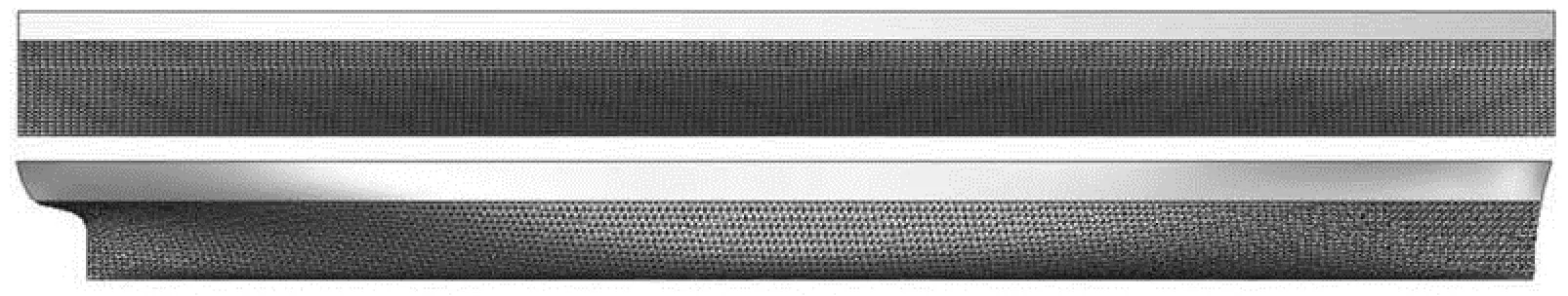
Fig.1 Wigley parabolic hull (top) and Series 60 (Cb=0.6) model (bottom)
Two major components of a ship drag are the“friction drag” and the “wave drag”, which are associated with viscous friction at the hull surface and wavemaking, and mostly depend on the Reynolds number and the Froude number, respectively. These two components are then considered here. Effects of sinkage and trim, viscosity, and nonlinearities on the drag are also considered. The sum of the friction drag given by the classical ITTC friction formula (for a smooth hull surface) and the wave drag predicted by the modification, called Neumann-Michell (NM) theory and given in Refs.[1-4], of the classical Neumann-Kelvin theory of ship waves is found to be within about 10% of experimental drag measurements for four ship hulls for which experimental measurements and theoretical predictions are compared. The sum of the ITTC friction drag and the NM wave drag can then be expected to yield realistic (although not very accurate) practical estimates that can be useful for routine applications to design and hull-form optimization of a broad range of ships. Furthermore, several extensions of this highly simplified approach can be expected to significantly improve accuracy.
1. Viscous friction and wavemaking
Two major components of a ship dragCtare the“friction drag”Cfand the “wave drag”Cwassociated with viscous friction at the hull surface and wavemaking. The friction dragCfand the wave dragCwmostly depend on the Reynolds numberReand the Froude numberFr, respectively. The dragCtcan then be expressed as
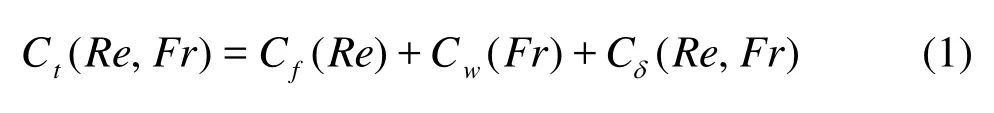
whereCδis the difference between the dragCtand the sumCw+Cfof the two major componentsCwandCf. The decomposition (1) provides a useful basis for the evaluation of the drag of a ship, as shown below.
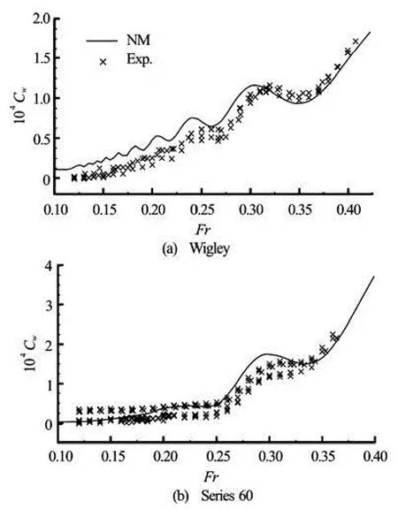
Fig.2 Wave drag predicted by the NM theory (NM) and experimental measurements of the residuary drag (Exp.) for the Wigley hull (top) and the Series 60 model (bottom) held“fixed” in their positions of equilibrium at rest (no sinkage or trim allowed)
A realistic estimate of the wave dragCwcan be obtained using potential flow theory with the linearized Kelvin-Michell boundary condition at the free surface. Specifically, the modification, expounded in Refs.[1-4] and called Neumann-Michell (NM) theory, of the classical Neumann-Kelvin theory of ship waves is used here to evaluate the wave dragCw. This practical theory provides a correction to the waves predicted by the classical Hogner approximation, which isdefined explicitly in terms of the ship speed, length and hull form.
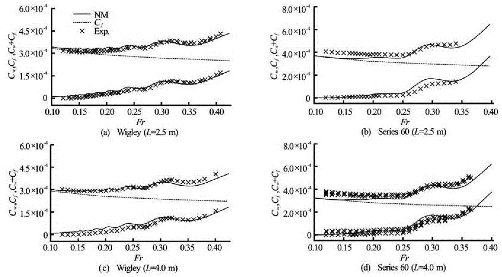
Fig.3 Wave dragCwpredicted by the NM theory and corresponding experimental measurements of the residuary drag (lower curves and data), ITTC friction dragCf(dashed line), and sumCw+Cfand experimental measurements of the dragCt(upper curves and data) for Wigley (left side) and Series 60 (right side) hulls of lengthsLm=2.5 m (top row) orLm=4 m (bottom row)
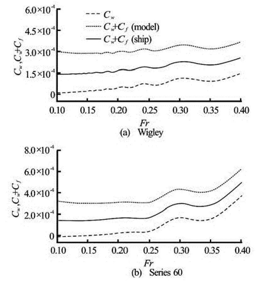
Fig.4 Wave dragCwpredicted by the NM theory, and sumCw+Cfof the wave dragCwand the ITTC friction dragCffor Wigley (top) and Series 60 (bottom) hulls of assumed model-scale lengthLm=4 m (model) or full-scale lengthLs=100 m (ship)
The NM theory yields realistic predictions of the wave dragCw(and other features of the flow around a ship hull), as now illustrated for the classical Wigley parabolic hull and the Series 60 (Cb=0.6) model depicted in Fig.1. This figure shows the sidesy≤0 of the Wigley and Series 60 hulls approximated by 8 000 flat triangular panels, used for the flow calculations. Figure 2 depicts the experimental measurements (Exp.) of the residuary drag reported in Refs.[5-7] and the predictions of the wave drag (determined via integration of the flow pressure at the ship hull surface) given by the NM theory (NM) for the Wigley hull (top) and the Series 60 model (bottom) depicted in Fig.1. The Wigley and Series 60 hulls are held “fixed” in their positions of equilibrium at rest (no sinkage or trim allowed) for both the NM flow evaluations and the experimental measurements shown in Fig.2.
A realistic estimate of the friction dragCffor a smooth ship hull surface is given by the classical ITTC friction formula
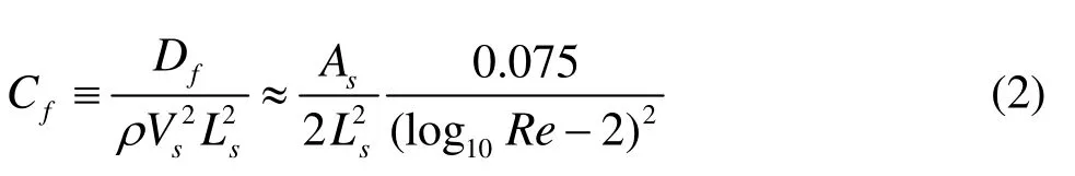
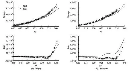
Fig.5 Experimental measurements (Exp.) and predictions given by the NM theory (NM) of the sinkage (top row) and the trim (bottom) experienced by the Wigley hull (left side) and the Series 60 model (right)
Figure 3 depicts the wave dragCwpredicted by the NM theory and the related experimental measurements of the residuary drag (already considered in Fig.2), the ITTC friction dragCf, the sumCw+Cfand the experimental measurements of the dragCtfor Wigley (left side) and Series 60 (right) hulls of lengthsLm=2.5 m (top row) orLm=4 m (bottom). The sumCw+Cfagrees relatively well with the experimental measurements of the total dragCt. Thus, the wave-and-friction dragCw+Cfin the decomposition (1) provides a reasonable estimate of the dragCtof a ship hull.
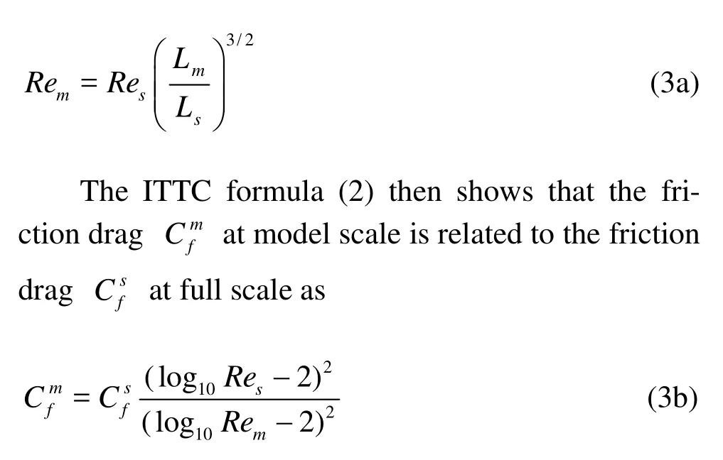
The drag of a ship is commonly measured experimentally by towing a ship model of lengthLmat the speedfor which the Froude number at model scaleLmis identical to the Froude number at full scaleLs. The Reynolds numberRemfor the ship model and the corresponding Reynolds numberResfor the full-scale ship are then related as For instance, at a scale factorLm=Ls/25, the relation (3a) yieldsRem=Res/125, and (3b) shows that we have?≈2?for a full-scale Reynolds numberRes=109. Thus, the dragCfdue to viscous friction is considerably larger at model scale than at full scale. This well-known fundamental model-scale distortion of the relative importance of the viscous drag is illustrated in Fig.4, where the wave dragCwpredicted by the NM theory (Cw) and the sumCw+Cfof the wave dragCwand the friction dragCfare depicted for Wigley (top) and Series 60 (bottom) models of lengthLm=4 m (model) or full-scale ships of lengthLs=100 m (ship). Figure 4 also shows that the friction dragCfor the wave dragCware the dominant drag components in the low-speed “friction” regimeFr<Frfor the high-speed “wavemaking” regimeFr>Frw, respectively, withFrf≈0.25 andFrw≈0.35 for a smooth hull at full scale, although the shape of the ship hull significantly affects the extent of the friction and wave regimes.
2. Sinkage and trim effects
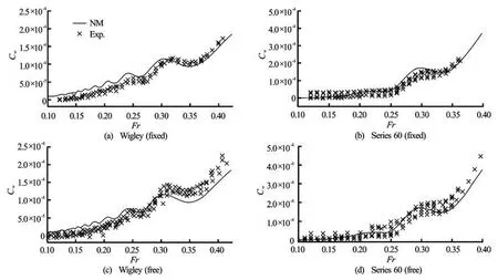
Fig.6 Wave drag predicted by the NM theory (NM) and experimental measurements of the residuary drag (Exp.) for the Wigley hull (left side) and the Series 60 model (right side). For the experimental measurements shown in the bottom and top rows, the models are “free” to sink and trim, or held ‘fixed’ in their positions of equilibrium at rest (no sinkage or trim allowed), respectively. The NM predictions shown in the top and bottom rows correspond to ‘fixed’ hulls (without sinkage or trim)
The dynamic flow pressure at a ship hull steadily advancing in calm water results in a hydrodynamic lift and pitch-moment that act upon the hull and cause the moving hull to sink and trim. The wetted hull surfaceof a ship advancing at speedVstherefore is not identical to the wetted hull surfaceof the ship at rest, as well known. Figure 5 shows experimental measurements (Exp.) of the sinkage (top row) and the trim (bottom) experienced by the Wigley hull (left side) and the Series 60 model (right). The sinkage and the trim predicted by the NM theory (NM), applied to the Wigley or Series 60 hullsat rest, are also shown in Fig.5. The difference between the wetted ship hull surfaceand the corresponding hull surface at restresults in variations of both the friction drag and the wave drag of the ship hull. These variations are now considered.
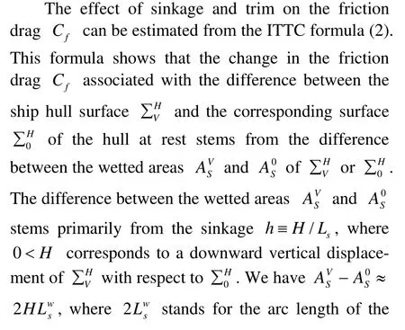
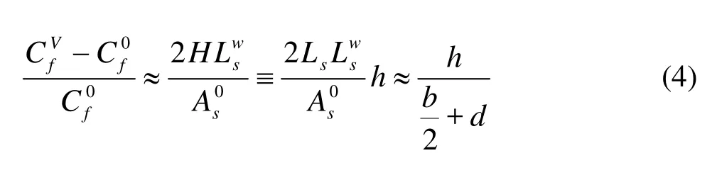
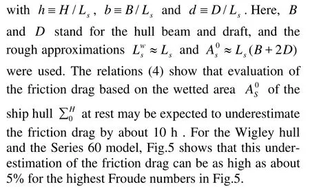
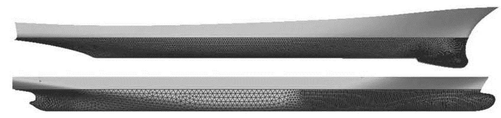
Fig.7 DTMB-5415 model (top) and KCS model (bottom)
Sinkage and trim effects on the wave dragCware now considered. An illustration of these effects is shown in Fig.6 for the Wigley hull (left side) and the Series 60 model (right). This figure depicts the experimental residuary drags (Exp.) for the “free” hullsallowed to sink and trim (bottom row), or the “fixed”hullsfor which no sinkage or trim is allowed in the experiments (top). The wave drags predicted by the NM theory (NM) applied to the “fixed” hullsare also depicted in Fig.6. Differences between the wave drags for the hullsandare appreciable, although not huge, for Froude numbersFrgreater than about 0.3. Furthermore, the bottom row of Fig.6 shows that the wave drags predicted by the NM theory for the hulls(without sinkage or trim) underpredict, but are in reasonable agreement with, the experimental residuary drags of the hulls.
Fig.8 Wave drag predicted by the NM theory (NM) and experimental measurements of the residuary drag (Exp.) for the DTMB-5415 hull (top) and the KCS hull (bottom) depicted in Fig.7
The NM theory is now applied to the DTMB-5415 model and the KCS model considered in Refs.[8, 9] and depicted in Fig.7. Specifically, the top and bottom rows of Fig.7 depict the sidesy≤0 of the DTMB-5415 and KCS hulls, respectively. These two (half) hulls are approximated by 9 928 or 9 452 flat triangular panels for the flow calculations. Figure 8 shows the experimental measurements (Exp.) of the residuary drag reported in Refs.[8,9] and the corresponding NM predictions (NM) of the wave drag for the DTMB-5415 hull (top) and the KCS hull (bottom) depicted in Fig.7. The NM flow calculations reported in Fig.8 were performed for the hullsin equilibrium positions when at rest (i.e., no sinkage or trim is considered in the calculations), whereas sinkage and trim are allowed for the experimental measurements.
The comparisons between NM predictions of the wave drag and experimental measurements of the residuary drag reported in Fig.8 and Fig.6 show that, for the four hull forms depicted in Fig.7 and Fig.1, the wave dragCwpredicted by the NM theory–applied to the hullin position of equilibrium at rest–provides a realistic estimate of the wave drag of the hullof the ship advancing with speedV.
s
3. Viscous effects
A characteristic transverse dimensionLBDof the ship hull is defined asLBD≡BD/(0.5B+D)whereBandDare the ship beam and draft. We haveLBD<BandLBD<2D. The hull slenderness is then

4. Nonlinear effects
Waves along a ship hull at midship–at some distance away from the ship bow and stern where the hull geometry varies rapidly–are largely determined by the ship speed. Specifically, “midship waves” are nearly sinusoidal, with wavelengthλ≈2π?/g. However, ship bow waves and stern waves–in the vicinity of a ship bow and stern–differ significantly from waves along a ship hull aft of the bow wave. Indeed, while waves along a ship hull aft of the ship bow are nearly sinusoidal as already noted, the portion of the wave profile between a ship stem and the crest of the bow wave, i.e., the bow wave front, is well approximated by a parabola[11,12]. A ship bow wave also contains more short divergent waves than waves along a ship hull aft of the bow wave, and is more directly affected by the hull geometry, specifically the shape of the ship bow. Indeed, a ship bow wave is strongly affected by near-field effects associated with a sudden change of flow direction at a ship bow[11].
Ship bow waves are then greatly affected by nonlinearities, which indeed cause two main flow regimes[11,13]. Fast ships with fine bows generate overturning bow waves that consist of detached thin sheets of water, which are roughly steady until they hit the water and undergo turbulent breaking up and diffusion. However, slow ships with blunt bows create highly unsteady and turbulent bow waves. The boundary between the “steady” overturning bow wave regime and the unsteady turbulent breaking bow wave regime follows from the upper boundEg/?≤0.5 for the elevationEof the free surface for steady flows[11].
5. Practical estimate of total drag
The foregoing brief elementary analysis of viscous and nonlinear effects shows that accurate numerical modeling of the flow around a ship hull steadily advancing in calm water requires CFD techniques that fully account for flow unsteadiness and turbulence, needed to properly model the bow wave and the flow near the stern, and that flow computations must be performed at full scale rather than at model scale (except of course for comparisons with model-scale experimental measurements). Furthermore, most ship hulls are not smooth surfaces, as commonly assumed, but rough. Such CFD computations of a ship drag are not practical, or indeed even necessary, for routine applications to ship design at early stages and hull-form optimization. Thus, we now consider the pragmatic alternative approach based on the sumCw+Cfof theITTC friction dragCfand the wave dragCwpredicted by the NM theory.
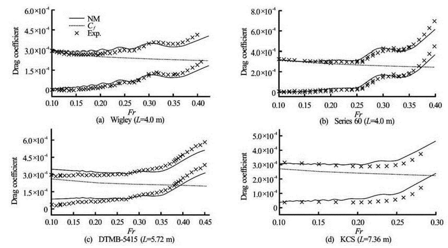
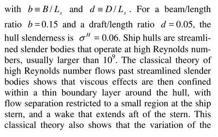
Fig.9 Wave dragCwpredicted by the NM theory and related experimental measurements of the residuary drag (lower curves and data), ITTC friction dragCf(dashed line), and sumCw+Cfand experimental measurements of the dragCt(upper curves and data) for the Wigley (top left corner), Series 60 (top right), DTMB-5415 (bottom left) and KCS (bottom right) models
Figure 9 shows the wave dragCwpredicted by the NM theory (lower curve), the ITTC friction dragCf(dashed line) and the dragCf+Cw(upper curve), and corresponding experimental measurements of the residuary dragCr(lower set of data) and of the total dragCt(upper set of data). The top row shows experimental measurements and theoretical predictions for the Wigley hull (left side) and the Series 60 model (right) of lengthLm=4 m that are depicted in Fig.1. The second row corresponds to the DTMB-5415 model (left) and the KCS model (right) depicted in Fig.7. The experimental drag measurements shown in Fig.9 correspond to “free” hullsallowed to sink and trim freely. The ITTC friction dragCfand the NM wave dragCwcorrespond to “fixed” hullsfor which effects of sinkage and trim are ignored. Figure 9 shows that the sumCf+Cwof the friction dragCfand the wave dragCwgiven by the ITTC formula (2) and the NM theory expounded in Refs.[1-4] provides a realistic estimate of the dragCtfor a range of d isplacement ship models.
Thisfinding is further illustrated in Fig.10 where the differenceCδ≡Ct-(Cf+Cw) is depicted for the four hulls considered in Fig.9. Specifically, Fig.10 shows the experimental dragCt(upper set of data), the theoretical dragCf+Cw(upper curve), the differenceCδ(lower set of data), and ±(Cf+Cw)/10 (two lower curves). This figure shows that the data corresponding to the differenceCδmostly lie between the two curves ±(Cf+Cw)/10. Thus, the error associated with the simple approximationCf+Cwis within about 10% of the dragCtfor the ship models considered in Fig.9 and Fig.10. This result also holds for the four additional ship hulls considered in Ref.[4].
6. Conclusions
The foregoing elementary analysis and comparisons between theoretical predictions and experimental measurements show that the sumCf+Cwof the friction dragCfand the wave dragCwgiven by the ITTC formula (2) and the NM theory expounded in Refs.[1-4] provides a realistic estimate of the dragCtof a ship hull. Specifically, Fig.10 shows that the error associated with the simple approximationCf+Cwcan be assumed to be within about 10% of the dragCtfor a broad class of displacement ships.
Fig.10 Experimental measurements of the dragCt(upper set of data), theoretical dragCf+Cw(upper curve), related (lower) curves ±(Cf+Cw)/10and (lower set of data) differenceCt-(Cf+Cw) for the four ship models considered in Fig.9
Thus, Fig.10 shows that, for a relatively broad class of ship hulls, the approximationCf+Cwaccounts for the dominant aspects of the physics of the flow around a hull advancing in calm water. Specifically, the influence of sinkage and trim, and of the complex features (notably flow unsteadiness and flow separation, nonlinear free-surface effects and wavebreaking) that are modeled in modern CFD methods (based on the URANS equations and turbulence models), essentially amount to a 10% correction to the predictions given by the simple approximationCf+Cw. Addition of CFD predictions to Fig.9 would provide a useful way of evaluating the improvements that can in fact be expected, for a range of Froude numbers and ship hulls, from the more precise account of flow physics considered in modern CFD methods.
While a 10% error in the prediction of the drag of a given ship hull may be too large for some practical purposes, hull-form optimization and the design process (notably at early stages) mainly require a hydrodynamic tool that can correctly predict if the drag of a hull is larger or smaller than the drag of a competing hull. This “ranking” (relative comparison) requirement indeed is critical for design and optimization. Although not considered here, a body of evidence[14-16], suggests that even an approximation based on a much less realistic flow model (slender-ship approximation) than the NM theory of ship waves considered here is usually able to provide correct relative comparisons of the drags of alternative hulls.
Furthermore, the approximation based on the ITTC friction drag and the NM wave drag can be corrected in several (simple) ways that may be expected to significantly improve accuracy. In particular, although sinkage and trim effects are ignored here, these effects can be fully taken into account in the NM theory. Figure 5 and Fig.9, and the elementary analysis given in Section 3, show that this correction for sinkage and trim can be expected to be most significant in the high Froude number rangeFr<0.3. Further improvements may be expected via a wake model to approximately account for flow separation near a ship stern, a correction (form factor) to the ITTC fri-ction drag, and corrections to the (linear) NM theory to approximately account for nonlinear effects.
Acknowledgement
This work was partly supported by the Office of Naval Research.
[1] NOBLESSE F., HUANG F. and YANG C. The Neumann-Michell theory of ship waves[J]. Journal of Engineering Mathematics, 2013, 79(1): 51-71.
[2] NOBLESSE F., DELHOMMEAU G. and HUANG F. et al. Practical mathematical representation of the flow due to a distribution of sources on a steadily-advancing ship hull[J]. Journal of Engineering Mathematics, 2011, 71(4): 367-392.
[3] NOBLESSE F., HUANG F. and YANG C. Evaluation of ship waves at the free surface and removal of short waves[J]. European Journal of Mechanics-B/Fluids, 2013, 38: 22-37.
[4] HUANG F., YANG C. and NOBLESSE F. Numerical implementation and validation of the Neumann-Michell theory of ship waves[J]. European Journal of Mechanics-B/Fluids, 2013, 42: 47-68.
[5] MCCARTHY J. H. Collected experimental resistance and flow data for three surface ship model hulls[R]. David W Taylor Naval Ship Research and Development Center, 1985, Report DTNSRDC-85/011.
[6] Experimental data for the Wigley hull are reported in cooperative experiments on the Wigley parabolic model in Japan[R]. Prepared for the 17th ITTC Resistance Committee. 2nd edition, 1983.
[7] Experimental data for the Series 60 model are reported in cooperative experiments on the Series 60 (Cb=0.6) model[R]. Prepared for the 18th ITTC Resistance Committee. 1986.
[8] OLIVIERI A., PISTANI F. and AVANZINI A.et al. Towing tank experiments of resistance, sinkage and trim, boundary layer, wake, and free surface flow around a naval combatant INSEAN 2340 model[R]. Iowa City, USA: University of Iowa, 2001, No. IIHRTR-421.
[9] KIM D. H., KIM W. J. and VAN S. H. Experimental investigation of local flow around KRISO 3600TEU container ship model in towing tank[J]. Journal of the Society of Naval Architects of Korea, 2000, 37: 1-10(in Korean).
[10] NEWMAN J. N. Marine hydrodynamics[M]. Cambirdge, Massachusetts, USA: MIT Press, 1977.
[11] NOBLESSE F., DELHOMMEAU G. and GUILBAUD M. et al. Simple analytical relations for ship bow waves[J]. Journal of Fluid Mechanics, 2008, 600: 105-132.
[12] SHAKERI M., TAVAKOLINEJAD M. and DUNCAN J. H. An experimental investigation of divergent bow waves simulated by a two-dimensional plus temporal wavemaker technique[J]. Journal of Fluid Mechanics, 2009, 634: 217- 243.
[13] DELHOMMEAU G., GUILBAUD M. and DAVID L. et al. Boundary between unsteady and overturning ship bow wave regimes[J]. Journal of Fluid Mechanics, 2009, 620: 167-175.
[14] LETCHER J. S., MARSHALL J. K. and OLIVER J. C. et al. Star and stripes[J]. Scientific American, 1987, 257: 34-40.
[15] PERCIVAL S., HENDRIX D. and NOBLESSE F. Hydrodynamic optimization of ship hull forms[J]. Applied Ocean Research, 2001, 23(6): 337-355.
[16] YANG C., SOTO O. and LÖHNER R. et al. Hydrodynamic optimization of a trimaran[J]. Ship Technology Research, 2001, 49(2): 70-92.
10.1016/S1001-6058(13)60409-6
* Biography: YANG Chi, Female, Ph. D., Professor

- 水动力学研究与进展 B辑的其它文章
- A one-dimensional polynomial chaos method in CFD–Based uncertainty quantification for ship hydrodynamic performance*
- Numerical analysis of cavitation within slanted axial-flow pump*
- Numerical simulation of hydro-elastic problems with smoothed particle hydrodynamics method*
- Analytic solutions of the interstitial fluid flow models*
- Experimental study of shell side flow-induced vibration of conical spiral tube bundle*
- A streamline approach for identification of the flowing and stagnant zones for five-spot well patterns in low permeability reservoirs*