
Erosion thermocouple temperature acquisition system
2013-11-01 01:26WANGFeiyue王飞跃ZHANGZhijie张志杰WANGWenlian王文廉
WANG Fei-yue(王飞跃), ZHANG Zhi-jie(张志杰), WANG Wen-lian(王文廉)
(College of Information and Communication Engineering, North University of China, Taiyuan 030051, China)
Erosion thermocouple temperature acquisition system
WANG Fei-yue(王飞跃), ZHANG Zhi-jie(张志杰), WANG Wen-lian(王文廉)
(College of Information and Communication Engineering, North University of China, Taiyuan 030051, China)
Aiming at high requirements of temperature measurement system in high temperature, high pressure, highly corrosive and other special environments, a temperature acquisition system based on field-programmable gate array (FPGA) which is the controller of the system is designed. Also a Flash memory is used as the memory and an erosion thermocouple is used as sensor of the system. Compared with the traditional system using complex programmable logic device (CPLD) and microcontroller unit (MCU) as the main body, this system has some advantages, such as short response time, small volume, no loss of data once power is off, high precision, stability and reliability. And the sensor of the system can be reused. In this paper, boiling water experiment is used to verify accuracy of the system. The millisecond level signal from firecrackers is for verifying the stability and fast response characteristics of the system. The results of experiment indicate that the temperature measurement system is more suitable for the field of explosion and other environments which have high requirements for the system.
Tungsten-Rhenium thermocouple; field-programmable gate array (FPGA); Flash memory
0 Introduction
The transient temperature measurement technology is always the key research at home and abroad, and the tested objects often occur in bad environment such as high temperature, high pressure, high corrosion and so on. Therefore there are higher requirements for the sensor and its measurement system. Recently, the system has greatly improved on the basis of the traditional temperature measurement system, by using single chip micyoco (SCM) and complex programmable logic device (CPLD) as controller, static random access memory (SRAM) for storage. Its advantages including upgrading and function expansion esaily, no loss of data when power goes off, higher stability and reliability, and response of the sensor is controlled and sensor is reused, etc[1-3].
This design uses erosion-type thermocouple applying to the explosion field with high corrosion resistance, high temperature and high pressure, which includes the thermocouple temperature sensor, signal disposal amplifier circuit, temperature compensation circuit, AD converter, Flash memory module, field programmable gate array (FPGA) controller circuit, and the battery[4-6]. The research is processed on how to obtain the rapid response and modular of the system program controller.
1 Overall design of the system
By analyzing the principle of thermocouple, the temperature acquisition system is designed using thermocouple, as shown in Fig.1.
In Fig.1, a powerful and high integrated programmable logic device, FPGA, is used as the core of the temperature measurement system which has a C expensive rhenium tungsten thermocouple temperature sensor of NANMAC company as the front end. When the sensor senses the temperature, the temperature signals are converted into electrical signals. After signals being conditioned, passing through AD, they are converted into 12-bit digital signals. After processed by first-in-first-out (FIFO) and FPGA, signals are compared and judged by the internal trigger module. According to the trigger state, FPGA takes corresponding control strategy on AD, FIFO and Flash module. Eventually, the data is stored in Flash memory. Data is extracted from Flash memory by FT245 via the internal USB control module of FPGA when reading. By FT245, the data is transferred to PC. Finally, the whole process of acquiring, storage and reading is completed. Here, 0, 1, 2, 5, 10, 20, 50 and 100 constitute the amplification coefficients of analog circuit of the system. The Flash memory has a storage capacity of 8 MB. The sampling frequency of AD is divided into 100 kHz, 500 kHz, 1 MHz, 2 MHz, which is adjustable. Also the negative delay is adjustable. CY7C4261V is a FIFO with a storage capacity of 16 KB.

Fig.1 Principle diagram of the system
2 Hardware circuit
2.1 Process and method of rapid responding erosion-type thermocouple
For self-updating thermocouples, some preparations must be done to make the thermocouple respond quickly. There are several methods to get quick response of the thermocouple.
The erosion thermocouple node ( self-updating thermocouple) is gained by grinding the end of sensor. This kind of connection form of nodes can make erosion thermocouple achieve a millisecond or even microsecond response time. Because of the special node, special attention has to be paid to the measurement of node resistance.
Turning the nodes (a line looks like a hair) of the thermocouple towards the flowing gas or liquid with 45°, according to description of the data sheet for erosion, is the suitable operation. This placement of the node makes sure that the erosion characteristics are maximized. If the induction end of thermocouple is oxidized, scratched or covered, the surface of induction end can be repaired by grinding.
If the loop resistance R1 of the thermocouple is more than lead resistance R2 plus 2-10 Ω (depending on wire length), new nodes have to be made. The specific procedure is as follows: Put a No.80 corundum sand paper (or alumina sand paper) on the smooth and hard surface. Make the thermocouple probe perpendicular to the ground at 45° toward the line of the node so as to grind conveniently. Grinding distance is 2-5 cm. Polishing with sand paper should be in the same direction but no dragging. Check the resistance of the nodes regularly, until achieving a stable consistent resistance (plus lead resistance) 2-10 Ω. This is the loop resistance of node. Chill the sensor for 10 s before the resistance measurement. In this way, we can get 10-20 ms response time easily when the temperature changes in levels.
To get a shorter response time, we can change size of the particles for scrubbing. Microsecond response can be got by using sand paper with grain of sand until the node is ground out. Once a node is polished out, the loop resistance will be greater than 1 000 Ω, which needs to use No.280-No.320 sand paper. Then there will be some high unstable resistance. Sand paper, a little thicker, can be used to gain a new node in the next step. Once the node resistance approaches about 8-12 Ω (depending on wire length), it will become the minimum/fastest thermocouple node, which creates the distinctive erosion type thermocouples. Any impurity or sediment cannot be in contact with induction head in use, or response time of the thermocouple will be increased, even touch of the sweat from skin could reduce the sensitivity. So it is important to keep the induction end under test clean.
Whether the thermocouple can be used correctly has a great influence upon the test results. If erosion type thermocouple is not polished following the steps above, we cannot get the ideal data or curve when the sensor is reused in the case of no grinding. Even considerable errors may be resulted.
2.2 Analog signal processing circuit
The analog signal processing circuit is shown in Fig.2. The circuit mainly includes power management, amplification, bias filter and temperature compensation. Working process of the analog circuit is as follows: When the thermocouple feels the outside temperature, the temperature signal is transferred into a potential signal, and the signal is transmitted to AD in the digital module after magnified and filtered by signal conditioning circuit.
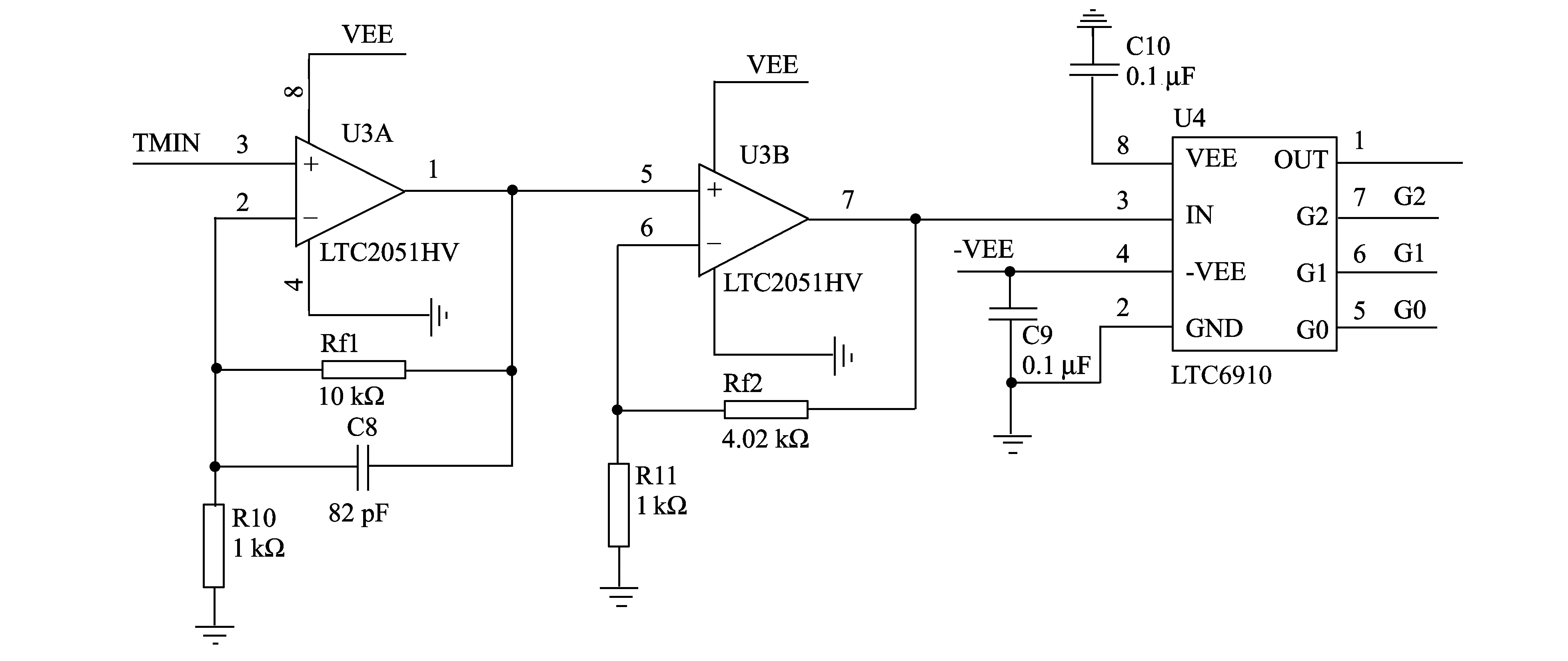
Fig.2 Analog signal processing circuit
The output voltage of power management is ±5 V. The signal is magnified 55 times by the first and second stages of the signal amplification circuit. The third stage is a programmable amplifier with eight adjustable magnifications which is followed by biasing circuit and second-order active filter. The cutoff frequency is

(1)
The result of calculation is f=194 kHz.
Output of the thermocouple is so small that impact of the drift to circuit voltage cannot be ignored. To improve precision of the system and reduce the voltage drift, high-precision resistance should be used in the circuit.
2.3 Digital signal processing circuit
Working process of digital signal processing circuit is as follows: Signal is transmitted to FIFO from the signal disposal section via AD and judged by FPGA. If the signal is greater than trigger level, the system begins to record useful data. System makes AD dormancy when the required data is enough. Then FIFO and Flash memory stop counting. After that, tie data is saved to the Flash memory eventually. The computer can read data at any time from Flash memory. The specific processes of digital signal processing circuit are shown in Fig.3.

Fig.3 Digital signal processing circuit module
The digital signal processing circuit includes power management, FPGA master controller, AD converter, FIFO and 256 MB Flash memory.
Power supply of 5V is supplied by power management circuit using LP2985. Voltages of 3.3 V and 1.2 V are supplied by TPS75003. They help the demands of FPGA, Flash, FIFO, FT245 and other chips to work well.
AD7482 is a digital-to-analog converter. Sampling rate is programmably set by AD controller module of FPGA, which includes 100 kHz, 500 kHz, 1 MHz and 2 MHz and is adjustable. It meets the requirements of different applications and data, which is widespread and ease of use.
The system uses Flash memory to store data avoding loss of data when power is off, which makes the system more suitable for the high-temperature, high-pressure and high-radiation harsh environment just like explosion field[7-9].
FIFO, which is conveniently controlled, not only makes the system get a data cache, but also makes it achieve negative delay of data. It ensures that the system saves 16 KB data before triggering, and it makes the data more reliable and more complete.
Devices above have corresponding function modules in FPGA and are programmed with hardware description language (VHDL). The traditional system with CPLD as a controller has not realized the function of the modularization in programming, which makes the program huge and muddled. The system cannot be optimized and improved expediently and is also shaky in reliability. Programming modules for AD controller, negative delay, FIFO control, Flash Memory reading and writing control and USB communication are convenient for system to upgrade, which makes the control of system more stable.
3 Overall flow chart based on FPGA
The system uses FPGA of the Spartan 3E series as controller. The controller is programmed with VHDL language, and machine of the data reading and writing is shown in Fig.4. The resources of FPGA is larger than CPLD, which solves problems of the traditional temperature test system with CPLD such as the system upgrade and more resources. Furthermore, table structure search makes the FPGA attain faster speed and stronger operation ability.

Fig.4 FPGA control flow chart
4 Experimental results and analysis
Fig.5 shows the experimental results. In Fig.5, the horizontal coordinate is time value and each lattice is 500 ms, the value of y-coordinate is bit. In the front, the level baseline value is 2 048 bit, and the full scale is 4 096 bit. The maximum of curve is 3 072 bit. Do the test trials with firecrackers, set the systematic magnification to 2 times, fix thermocouple, cut off half of the firecracker, show the gunpowder, aim at the thermocouple sensitive surface, fire the firecracker, and read data by temperature testing system of LabVIEW. The value of a signal obtained is Y=3 072 bit. The output voltage of sensor is calculated by

Fig.5 Temperature response curve

(2)
The unit of U is mV. Put Y=3 072 bit into Eq.(2), then U=5.586 mV. By comparing the sensor thermocouple indexing table, the temperature is got, Z1=354 ℃. Output value of the cold end temperature sensor DS600 is X=188 bit, and the formula is
The unit of Z2is degree. Put X into Eq.(3),then Z2= 15 ℃. Z1is just the difference between burning temperature of the gunpowder and cold end temperature, so the real temperature is Z1and Z2.
The boiling water from water fountain is used in water temperature testing. The thermocouple is inserted into hot water under test. The thermocouple should be taken out of water two min later after the system is triggered. Reading data by program temperature testing system of LabVIEW, value of the signal obtained is Y=2 194 bit. Put Y into Eq.(2), then U=0.810 mV. By comparing the sensor thermocouple indexing table, T1=61 ℃ is got. Output value of the cold end temperature sensor is X=204 bit. Put X into Eq.(3), then T=23 ℃. So the measured temperature of hot water is 84 ℃. Actual temperature of the water from water fountain is 85 ℃ which is given by a thermometer. Thus, the result is proved to be reliable and the temperature acquisition system is accurate enough[10,11].
5 Conclusion
According to the bad environment (such as shooting range, high temperature furnace, etc), the erosion thermocouple temperature acquisition system is designed in this paper, and the process and method of fast response are researched. Effectiveness of the system is proved by the firecrackers experiment. Compared with the traditional system with CPLD, single chip and SRAM memory, advantages of this system are such as faster response time, smaller size, higher accuracy, data retainment when power goes off, higher stability and reliability, more adequate function expansion space of FPGA, sensor reusing, more suitable for the environment with high temperature and pressure, such as the explosion field.
[1] Monica A C. Temperature measurement and acquisition system with smart temperature sensor. Serie Electrotechnique et Energetique, 2004, 49(1): 143-150.
[2] Grempler K. An improved airborne ocean temperature acquisition display and ananlysis system. Johns Hopkins Apl Technical Digest, 1993, 14(3): 253-258.
[3] LI Gong-qi, LI Dong-guang. Based on the high-speed CPLD the missile test system storage key techniques. Journal of theArrows and Guidance, 2007, 27(1): 360-362.
[4] KONG Wen-chuang, WANG Dai-hua, ZHANG Zhi-jie. A new temperature collection system. Nuclear Electronics & Detection Technology, 2011, 31(1): 73-78.
[5] REN Quan-hui, MA Lei. Design and implementation of temperature acquisition system based on FPGA and AT89C2051. Coal Technology, 2011, 12: 48-50.
[6] WU Lei, SHEN Shi-tao, GUO Chao-ping, et al. Design of embedded temperature acquisition system based on USB and FPGA. Journal of Computer Applications, 2011, 31(2): 222-224.
[7] ZU Yi-kang. Multiplex temperature collection system based on type-k thermocouple and MAX6675. Journal of Jiangxi University of Science and Technology, 2007, 4: 25-27.
[8] PAN Xue-tao, LI Lang, MENG Qing-yang, et al. Design of thermocouple temperature measurement system based on virtual instruments and USB technology. Computer Measurement & Control, 2011, 10: 2340-2343.
[9] TAO Wei-wei, LIU Ying-jie, XI Zhen-hua, et al. Wireless building temperature gathering system based on CC1110. Microcomputer & Its Applications, 2012, 1: 19-22.
[10] CHEN Ming-bao. Research on hardware performance for thermocouple temperature measurement modules. Automation & Instrumentation, 2012, 6: 16-20.
[11] ZHEN Guo-yong, WANG Xiang-ling, HOU Zhuo. Signal processing circuit of temperature measurement based on thermocouple. Nuclear Electronics & Detection Technology, 2012, 32(3): 269-271.
date: 2012-10-25
Natural Science Foundation of Shanxi Province (No. 2009011023)
WANG Fei-yue (wangfeiyue1985@163)
CLD number: TP274+.2 Document code: A
1674-8042(2013)01-0014-05
10.3969/j.issn.1674-8042.2013.01.004
 Journal of Measurement Science and Instrumentation2013年1期
- Journal of Measurement Science and Instrumentation的其它文章
- Radiation characteristics of ring patch antennas with capacitive feed patch
- Acetonitrile (CH3CN) and methyl isocyanide(CH3NC) adsorption on Pt(111) surface: a DFT study
- Image enhancement and post-processing for low resolution compressed video
- Dynamic calibration method of capacitive pressure measuring device
- Automatic measurement of air-pressure sensor based on two-pressure control instrument
- An experiment to estimate the revolution of DC motor