
SIMULATION OF TEMPERATURE FIELD IN ULTRA-HIGH FREQUENCY INDUCTION HEATING AND VERIFICATION
2013-12-02 01:39LiQilin李奇林XuJiuhua徐九华SuHonghua苏宏华
关键词:九华
Li Qilin(李奇林),Xu Jiuhua(徐九华),Su Honghua(苏宏华)
(College of Mechanical and Electrical Engineering,Nanjing University of Aeronautics and Astronautics,Nanjing,210016,P.R.China)
INTRODUCTION
Induction heating is one of the most widely used methods for heating treatment of steel.It provides faster and more precise heating of local areas,consumes less energy and is considered more environmentally friendly than other methods[1-3].In general,the exciting frequency above 5—10times of the previous can be called ultrahigh frequency induction heating.According to the skin effect,the induced current density mainly distributes on the surface along workpiece thickness (radius).Approximately 86%of the power will be concentrated in the surface layer of workpiece,which is called skin depthδ,and described in meter as[4]
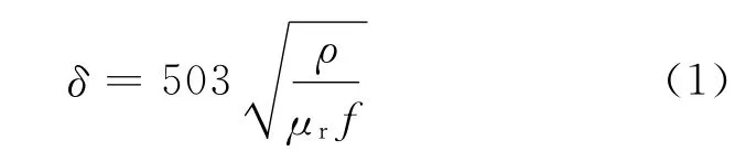
whereρis the electrical resistivity of the workpiece,μrthe relative magnetic permeability,and fthe current frequency.
When applying induction current with higher frequency,especially ultra-high frequency,the Joule heat concentrates more likely on the surface of workpiece.Therefore,much higher heating efficiency and faster temperature increase can be achieved.Besides that,the deformation of workpiece can decrease remarkably with localized heating.
Because of the dramatic advantages mentioned above,induction heating with ultra-high frequency comes to industrial applications in recent years.It is suitable for small workpiece treating or localized heating for large-scale workpiece,such as razor blade impulse hardening,metallic spectacle frames brazing,etc[5].
On the other hand,induction heating is a complex process including electromagnetic,thermal and metallurgic phenomena. During the process of induction heating,the temperature of the heated material changes on such a large scale that introduction of non-linear temperature-dependent material properties is necessary[6-8].Therefore,the planning of induction heating sys-tem,including choosing the proper shape and position of the coil and adjusting the electric current properties to attain a desired temperature profile in the workpiece,is difficult.As a result,numerical methods such as finite element method through computer calculation are necessary and have been used extensively[9-13].However,the previous research focused on the high frequency induction heating[14-15],while the characteristic of the temperature field induced in ultra-high frequency induction heating is not involved yet.
In order to investigate the temperature distribution characteristic in ultra-high induction heating,and with an aim of predicting the thermal history of the workpiece,the numerical simulation of temperature field in ultra-high frequency induction heating is implemented by using FLUX 2Dsoftware.The experiment is carried out to validate the numerical simulation result.Furthermore,the influence facts such as the induction frequency,the gap between coil and workpiece and the dimensions of coil on brazing temperature field induced in the workpiece are investigated and discussed.
1 PHYSICAL DESCRIPTION AND EXPERIMENTAL SETUP
Fig.1(a)shows the schematic of ultra-high frequency induction heating,which consists of 50mm×50mm×10mm ISO C45plate,rectangular-type oxygen-free high conductivity copper coil and C-shaped ferrite core.Here the dimension of coil cross-section is rectangular 2mm×3mm (the width of coil a=2mm),which is surrounded by C-shaped ferrite core.The gap between coil and workpiece his 2mm (Fig.1(b)).The ultra-high frequency induction heating power supplies the power of 6kW with the frequency of 1MHz.The actual setup for experiment is shown as Fig.1(c).The temperature signal is collected by a thermocouple which is placed on the surface of metallic workpiece.The thermoelectric potential signal is input to the computer through a data acquisition card.Since the thermocouple is conductive and in the ultra-high frequency electromagnetic field,electromotive force will be induced,which is the interference on the thermoelectric signal.In order to minimize the induced electromotive force,the two of the thermocouple wires are put in each side of the vertical direction of the coil respectively.As a result,the magnetic flux that passes through the thermocouple loop is nearly zero,and the induced electromotive force is negligible.
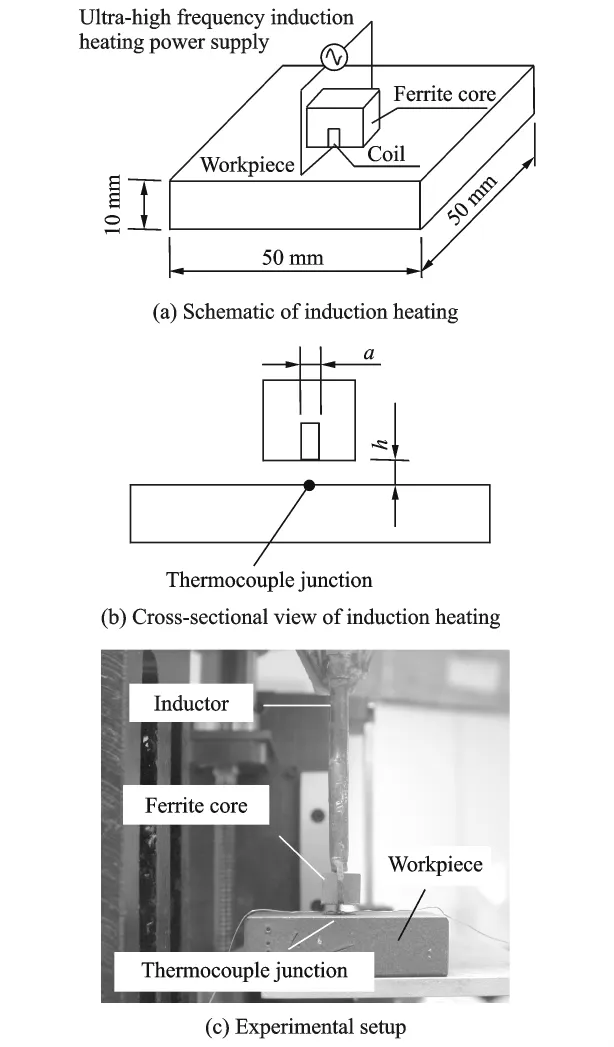
Fig.1 Physical description of induction heating
2 FINITE ELEMENT MODEL AND CALCULATION
2.1 Magnetic-thermal coupling method
Since the material properties of the ISO C45 steel are temperature dependent,the finite element calculation is performed using the magnetic coupled to transient thermal module.Since the electrical and magnetic property laws depend on temperature,a high coupling grade between thermal and electromagnetic equations arises.In fact,the heat source consists of the eddy currents induced by the magnetic field variations (Joule effect).Fig.2shows the flowchart of coupled electromagnetic thermal analysis of induction heating for steel workpiece.The time axis of the thermal calculation is divided into micro step,Δt.When the initial temperature is known,the intensity of the eddy current value can be calculated by electromagnetic analysis.This value is then used to compute the heat generated by the Joule effect.According to the specific heat capacity Cpof the C45steel,the temperature can be determined through thermal analysis.For each magnetic substep,the temperature value is recalculated until a steady state between the heat generated by the Joule effect and the temperature field,resulting from the thermal analysis,is reached[10].
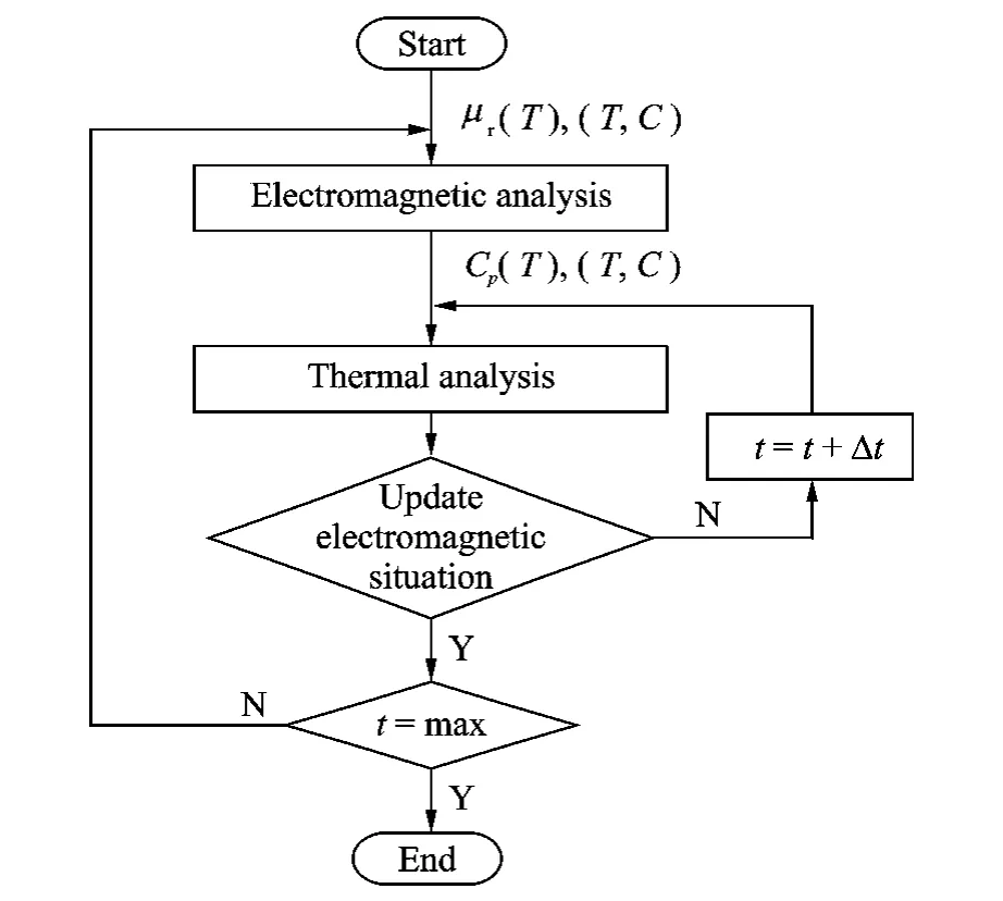
Fig.2 Flowchart of coupled electromagnetic thermal analysis
2.2 Geometry model and mesh
Finite element analysis is carried out using commercial FLUX®2Dsoftware.Finite element models are shown as Fig.3.For the axisymmetrical conditions,only a half section of the whole geometry is modeled.
There are at least two meshes in the skin depth to ensure the calculation accuracy in view ofthe noticeable skin effect of the ultra-high frequency electromagnetic field in workpiece and coil[12].In this study,the frequency of electromagnetic field is 1MHz,so according to Eq.(1),the skin depth of coil and workpiece is 8×10⁻²mm and 2×10⁻²mm respectively.Correspondingly,the finest meshes of the skin layer of coil and workpiece are 2×10⁻²mm and 6×10⁻³mm.Although the meshes can be further refined,the numerical accuracy cannot be further improved.The mesh scheme is shown in Fig.4.To improve the numerical accuracy,the surface layer of metal and the air domain close to the exciting source of electromagnetic field must be finely meshed.On the contrary,the meshes of the inner part of workpiece and the air domain,far from the exciting source of electromagnetic field,where the gradient is small,should be enlarged for the purpose of enhancing the computational efficiency.
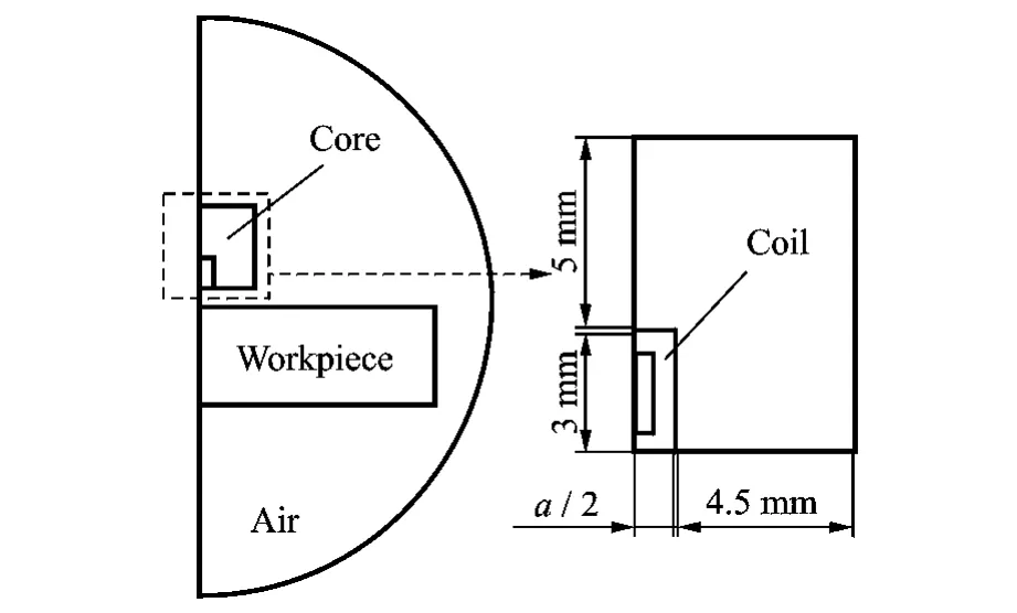
Fig.3 Geometry model
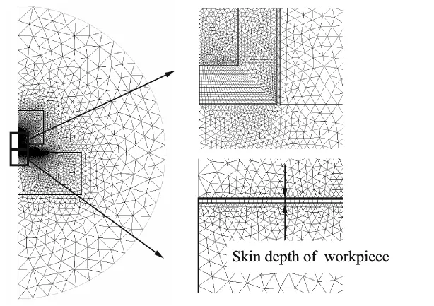
Fig.4 Mesh scheme
2.3 Magnetical properties of workpiece
Thermal and magnetic properties of the ISO C45steel are temperature dependent.Specific heat Cp(J/(kg· K)),thermal conductivity λ(W/(m·K)),electric resistivityρ(Ω·m),and relative permeability,are functions of temperature T and their values are shown in Fig.5[15].
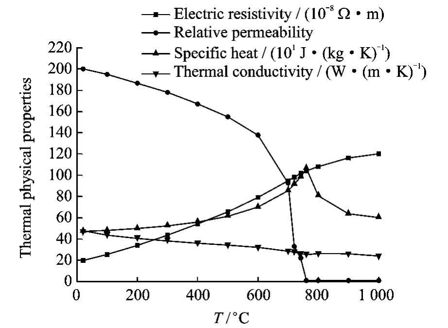
Fig.5 Material properties of ISO C45steel
3 SIMULATION RESULTS AND DISCUSSION
3.1 Experimental verification
The surface temperature history of workpiece at different exciting currents of ultra-high frequency(f=1MHz)induction heating using temperature-dependent material properties is shown in Fig.6.The workpiece is heated for 15sand then cooled down in the air.Moreover,a comparison between experimental and simulation results is also illustrated,and a relatively good agreement between them can be observed.The maximum error is about 7.9%which occurs at t=2.5sand I=30A,where the simulation and experimental values are 1 001,1 087°C respectively.There may be minor measurement errors due to strong electromagnetic interferences caused by ultra-high frequency electric currents in the induction coil.However,these interferences are negligible comparing with thermoelectric signal.It can be drawn the conclusion that the numerical model and simulation results are both reliable.
3.2 Influence of induction frequency on temperature
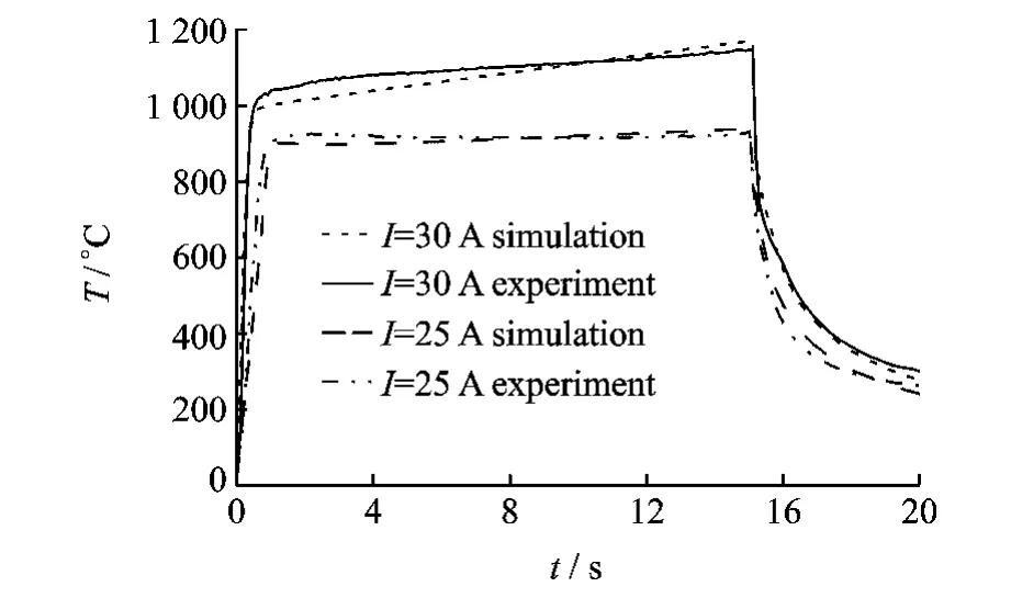
Fig.6 Surface temperature of workpiece at different exciting currents
According to Eq.(1),with the induction fre-quency fincreasing,the skin depth decreases,and the heat source concentrates on the surface of workpiece.The simulation result demonstrates the influence of induction frequency on surface temperature,and is illustrated in Fig.7.Here the dimension of coil cross-section is rectangular 2mm×3mm,h=2mm,and I=30A.It is shown that the increase of surface temperature becomes slow when the induction frequency decreases.Besides that,the surface temperature has nonlinear relationship with the induction frequency.It can be seen that the temperature rises very slowly and reaches about 600°C at the end of heating when f=100kHz.While in the other cases,the surface temperature is in the range from about 900°C to 1 100°C at the end.The surface temperature increases slowly at the beginning when the frequency fis less than 500kHz.On the contrary,when the frequency fis more than 500kHz,the surface temperature raises very fast and reaches above 900°C within 0.4s.As a result,ultra-high frequency induction heating has the advantage of faster heating rate and temperature.
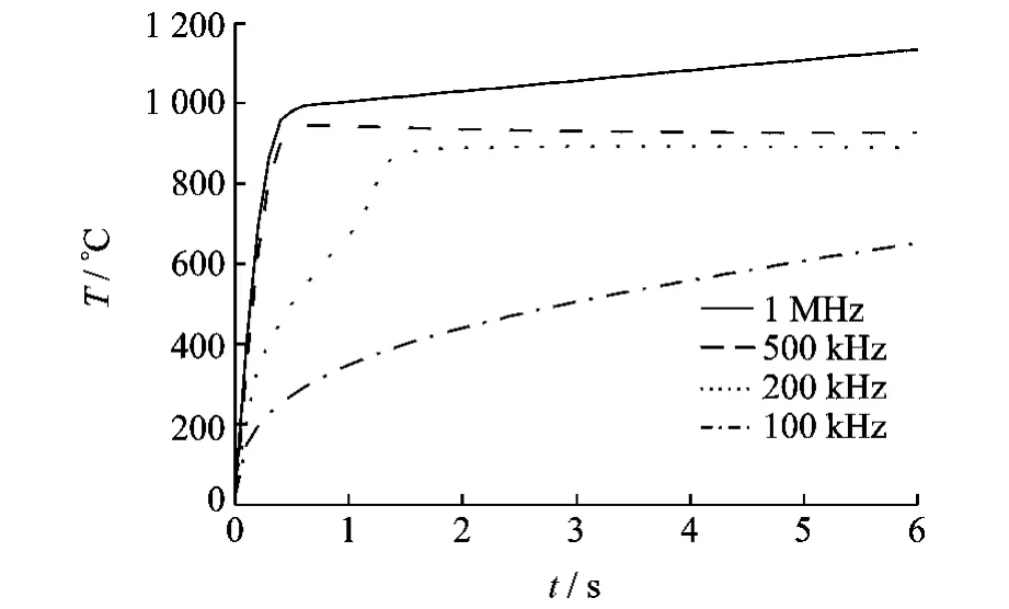
Fig.7 Surface temperature of workpiece at different induction frequencies
3.3 Influence of gap on temperature
The maximum surface temperature on workpiece after heating for 6sis shown in Fig.8.Here the dimension of coil cross-section is rectangular 2 mm×3mm with f=1MHz and I=25A.The maximum surface temperature decreases from 1 600°C to 760°C with the gap h becoming wider.Fig.8also indicates a fact that the influence of gap on maximum temperature is nonlinear.With the gap becoming wider,the temperature decreases significantly at the beginning,and then decreases slowly down.The curve fitting equation of the simulation results can be expressed as

where Tis the maximum surface temperature.Eq.(2)demonstrates that the maximum surface temperature is in inverse proportion to the gap between coil and workpiece.
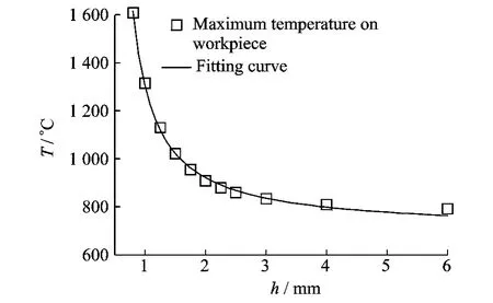
Fig.8 Maximum temperature versus gap
In order to simplify the problem,the dimension of coil in single-pass induction heating can be ignored.And the current passes through the coil.Therefore,the total power Pgenerated by induction in workpiece is in inverse proportion to the gap between coil and workpiece h,and is determined as[1]whereδis the skin depth in workpiece,and Ithe current in coil.
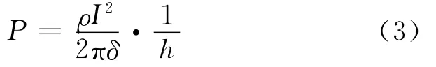
The total power P transforms mostly to Joule heat causing the temperature of the workpiece increasing.In this sense,it can be qualitatively concluded that the higher power Pin the workpiece means higher surface temperature.As a result,with the gap between coil and workpiece h becoming wider,the surface temperature decreases rapidly.
3.4 Influence of dimension of coil section on temperature distribution
Fig.9shows the simulation result of temperature distribution cloud chart with varying width of coil a.Here h=1.5mm,f=1MHz and I=25A.It can be seen that with the width of coil a increasing,the width of heated area in workpiece increases slightly.The width of main heated area is about 2mm in all cases.The maximum temperature in workpiece decreases from 1 080°C to 850°C with the width of coil aincreasing(Fig.10).It indicates that the dimension of coil section have small influence on temperature distribution in this study.The coil structure mainly has influence on the maximum temperature in workpiece.
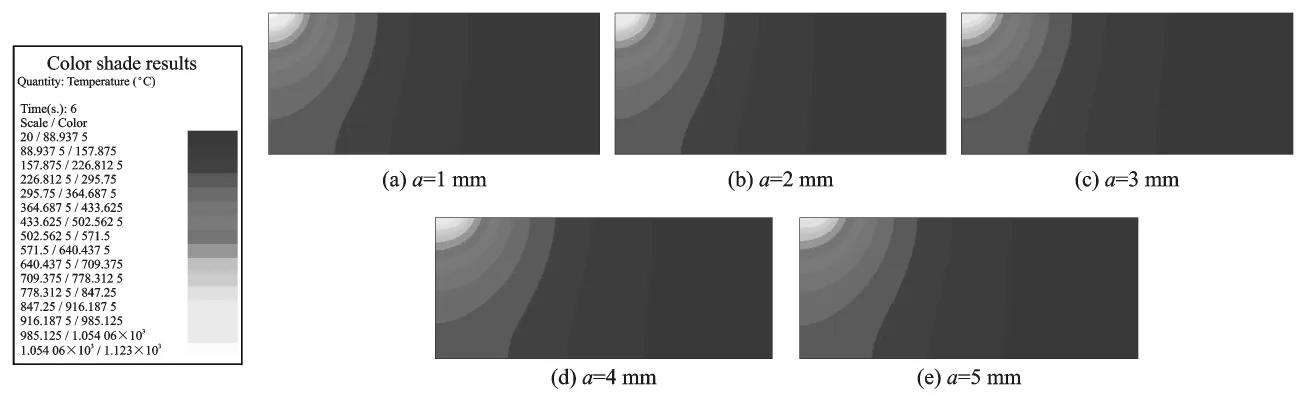
Fig.9 Temperature distribution cloud chart with varying width of coil
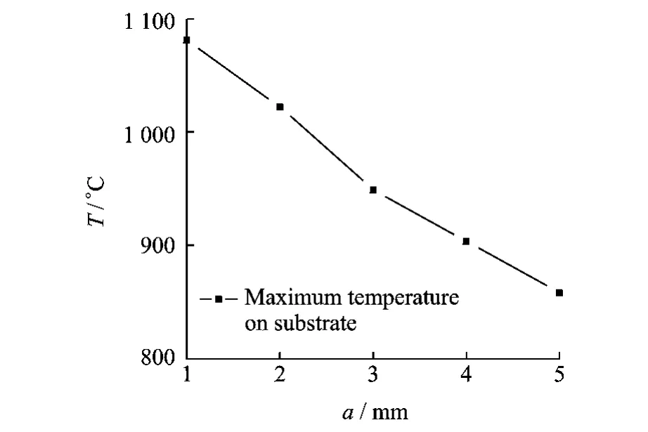
Fig.10 Maximum temperature versus width of coil
During induction heating,the eddy current distribution is considered approximately as the projection of coil geometry on workpiece surface[14].The smaller the size of coil section is,the narrower the width of the projection of coil geometry on workpiece surface is.Therefore,the density of eddy current is stronger under the condition of the same heating power supply.Consequently,much higher heating rate and temperature can be achieved.
4 CONCLUSIONS
(1)The numerical model of induction heating solving the temperature field is described taking temperature-dependent material properties into account.The experiment is carried out to verify the numerical simulation result.A good agreement is observed between experimental result and numerical value with 7.9%errors.The numerical model and simulation results are both reliable.
(2)Numerical simulation results indicate that the increase of surface temperature becomes faster when the induction frequency fincreases.Ultra-high frequency induction heating has the advantage of lower skin depth,and faster heating rate, when the frequency f is more than 500kHz.
(3)The maximum surface temperature of workpiece is in inverse proportion to the gap be-tween coil and workpiece h.With the gap h becoming wider,the maximum surface temperature decreases rapidly.
(4)The dimension of coil section ahas small influence on temperature distribution in this study.And it mainly has influence on the maximum surface temperature of workpiece.
[1] John D,Peter S.Induction heating handbook[M].London:Mcgraw-hill book Company(UK)Limited,1979:139-140.
[2] Ma Bojiang,Xu Hongjun,Xiao Bin,et al.Interfacial characteristics of diamond brazed by high-frequency induction[J].Transactions of the China Welding Institution,2005,26(3):50-54.(in Chinese)
[3] Xu Zhengya,Xu Hongjun,Fu Yucan,et al.Induction brazing diamond grinding wheel with Ni-Cr filler alloy[C]//12th Internation Manufacturing Conference.Switzerland:Trams Tech Publications Ltd,2006:377-380.
[4] Valery R,Don L,Raymond C,et al.Handbook of induction heat[M].New York:Marcel Dekker Inc.,2003.
[5] Nemkov V.Frequency selection for induction heattreating operations[J].Industrial Heating,2005,72(5):61-63.
[6] Enokizono M,Tanabe H.Numerical analysis of high-frequency induction heating includeing temperature dependence of material characteristics[J].IEEE Transactions on Magnetics,1995,31(4):2438-2444.
[7] Drobenko B,Hachkevych O,Kournyts′kyi T.A mathematical simulation of high temperature induction heating of electroconductive solids[J].International Journal Heat Mass Transfer,2007,50(3/4):616-624.
[8] Sun Y,Sun J,Niu D.Numerical simulation of induction heating of steel bar with nonlinear material properties[C]//Proceedings of the 2009IEEE International Conference on Automation and Logistics.Piscataway,NJ,USA:IEEE,2009:450-454.
[9] Shen H,Yao Z Q,Shi Y J,et al.Study on temperature field induced in high frequency induction heating[J].Acta Metallurgica Sinica (English Letters),2006,19(3):190-196.
[10]Magnabosco I,Ferro P,Tiziani A,et al.Induction heat treatment of a ISO C45steel bar:Experimental and numerical analysis[J].Computational Materials Science,2006,35(2):98-106.
[11]Matej K,Anze Z,Damijan M,et al.Numerical analysis and thermographic investigation of induction heating[J].International Journal of Heat and Mass Transfer,2010,53(17/18):3585-3591.
[12]Yu Enlin,Han Yi,Fan Yuliu,et al.Simulation of coupling of electromagnetic and thermal fields for process of high-frequency induction heating of HFW pipe[J].Transactions of the China Welding Institution,2010,31(4):5-8.(in Chinese)
[13]Lee K S,Eom D H,Kim S W,et al.A study on temperature distribution and curved structure for thick plate by single-pass induction heating[C]//10th International Conference on Numerical Methods in Industrial Forming Processes.USA:American Institute of Physics,2010:659-665.
[14]Yang Xiaoguang,Wang Youhua.The effect of coil geometry on the distributions of eddy current and temperature in transverse flux induction heating equipment[J].Heat Treatment of Metals,2003,28(7):49-54.(in Chinese)
[15]Arita H,Todaka T,Enokizono M.Thermal magnetic characteristic for high frequency induction heating analysis[J].Journal of Applied Physics,2002,91(10):8317-8318.
猜你喜欢
清风(2022年12期)2023-01-03
小学生学习指导(中年级)(2021年12期)2021-12-30
宝藏(2020年5期)2020-10-17
作文·小学低年级(2020年8期)2020-10-09
宝藏(2019年5期)2019-06-21
作文周刊·小学三年级版(2016年42期)2017-06-05
中国医疗保险(2017年1期)2017-05-18
股市动态分析(2016年27期)2016-07-26
 Transactions of Nanjing University of Aeronautics and Astronautics2013年2期
- Transactions of Nanjing University of Aeronautics and Astronautics的其它文章
- FLEXURAL CAPACITY OF RC BEAM STRENGTHENED WITH PRESTRESSED C/AFRP SHEETS
- MINIMUM ATTRIBUTE CO-REDUCTION ALGORITHM BASED ON MULTILEVEL EVOLUTIONARY TREE WITH SELF-ADAPTIVE SUBPOPULATIONS
- OUTPUT MAXIMIZATION CONTROL FOR VSCF WIND ENERGY CONVERSION SYSTEM USING EXTREMUM CONTROL STRATEGY
- ACTIVE VIBRATION CONTROL OF TWO-BEAM STRUCTURES
- IMPROVED DOPPLER WARPING METHOD FOR AIRBORNE RADAR WITH NON-SIDELOOKING ARRAY
- MULTI-OBJECTIVE PROGRAMMING FOR AIRPORT GATE REASSIGNMENT