
Effects of Thermo-Mechanical Loads on Aeroelastic Instabilities of Metallic and Composite Panels
2014-04-24 10:53ErasmoCarreraMariaCinefraEnricoZappinoLorenzoSucci
ErasmoCarrera,Maria Cinefra,Enrico Zappino**,Lorenzo Succi
1.Department of Mechanical and Aerospace Engineering,Politecnico di Torino,Corso Duca degli Abruzzi 24,10129Torino,Italy;2.School of Aerospace,Mechanical and Manufacturing Engineering,RMIT University,Melbourne,Australia
1 Introduction
Panel flutter is an aeroelastic phenomena that can cause failure of panels of wings,fuselages,and missiles.The panel flutter phenomena involves mainly the aeronautic structures but it appears also on space structure during the coasting phase.The new launcher generations try to improve the performance by introducing new panels,and they must protect the cryogenics stage during the coasting phase.These panels,called the versatile thermal insulation(VTI)panels,are bigger than the common aeronautical panels and usually are connected with the main structure by means of pinched points.The dimension,the boundary conditions(BCs)and the weight requirements make the VTI panels very flexible and so they may easily occur in aeroelastic phenomena.The aerodynamic heating on the external surface and the cryogenic fluid on the inner surface,create a high thermal gradient along the thickness of the panel.The stress field due to the differential thermal loads could strongly affect the dynamic behavior of the panel and can plays an important role in the aeroelastic instability,as shown by Dixon et al[1].
The analysis of composite structures subjected to thermal loads is a challenging problem and many works were presented on this topic.A valuable example are the works by Noor and Burton[2],as well as Khdeir[3].Carrera[4-5]proposed the use of advanced structural models in the thermo-mechanical analysis of composite panels in order to introduce a more refined solution over the panels thickness.The improvements introduced by the use of refined models allow a non-constant temperature profile to be considered obtaining accurate results,as shown in Ref.[5].More recent application of higher-order shell models to the thermo-mechanical analysis are those by Wu and Chen[5],as well as Fazzolari and Carrera[6].
In this paper,an aero-thermo-mechanical analysis is performed using a refined shell theory[7]for the structural model including the thermal effects and the Piston theory[8],in its linear form,for the aerodynamic loads.A cylindrical shell finite element derived by means of the Carrera unified formulation(CUF)[9]is adopted.The higher-order models derived by means of the CUF approach allow the thermo-mechanical problem to be addressed with very high accuracy.Different material laminations are considered:isotropic,composite,and sandwich material.Only supersonic regimes are investigated.The results show that the thermal loads can afflict the aeroelastic behavior of the panel.The results also show the effect of the use of the refined shell elements respect to the classical one.The advantages of these models are pointed out mainly in the composite and sandwich panels.
2 Aeroelastic Model
The aeroelastic model used in the present work can be derived imposing the equilibrium of the work virtual variations.The principle of virtual displacement(PVD)states that

where Lintis the work due to the elastic forces,Linethe inertial work,Laerthe work made by the aerodynamic forces,and Lheatthe thermal work.δ denotes the virtual variation.If the solution is supposed to be harmonic and the contributions are expressed in a matrix form,the previous Eq.(1)becomes
From left to right,it is possible to see the mass matrix of the structure M,the aerodynamic dumping matrix Da,the structural stiffness matrix K,the aerodynamic stiffness matrix Ka,and finally the thermal stress matrix Kheat.The matrices are derived in terms of fundamental nuclei,a 3×3matrix that is independent of the used model.The CUF approach is used both for structural and aerodynamic matrices.More details on CUF can be found in Refs.[9-10].
2.1 Unified formulation
The generic three-dimensional(3D)displacement model can be written as

The 3Dformulation can be reduced to the two-dimensional(2D)formulation by introducing the function Fτ.This function introduces an expansion over the thickness of the structure.Therefore the displacement field can be written as

where Fτis a function expansion used to approximate the displacement over the thickness of the structure.The formulation of the expansion can be assumed by using an equivalent single layer(ESL)approach or in a layer wise(LW)formulation(see Ref.[9]).The former approach uses a global approximation over the thickness,and the latter is able to provide a local description introducing an expansion over each layer.The finit element method(FEM)approach is used to solve the problem over the reference surface.By introducing the shape functions Ni,the displacements can be written in the following formulation

where Niare the Lagrange functions and Kis the number of node of the used element.
2.2 Elastic work
The elastic work can be derived by the classical formulation of stress and strain

The expression of D can be found in Ref.[11].The components of Care the material coefficients whose explicit expressions are not reported here for the sake of brevity,they can be found in Ref.[5].The internal work can be written as

2.3 Inertial work
The mass matrix formulation derives from the variation of the work made by the inertial forces
A single dot denotes the derivative with respect to time,therefore,in the case of the displacement vector u,double dots denote acceleration.
2.4 Thermal work
The strain and the stress fields related to the thermal load is assumed as

whereαpcontains the in-plane thermal expansion coefficients along the x,yand xydirections,ΔT is a vector(3×1)containing the temperature gradient and Cpis the in-plane material matrix coefficients.In order to obtain the fundamental nuclei the Von Karman non-linear formulation is used
For thin structures,the fundamental nuclei of thermal stress matrix(3×3)has only the third diagonal element different from zero,and the other can be assumed negligible.The complete formulation can be found in Ref.[6].
2.5 Aerodynamic work
The aerodynamic forces are described using the Piston theory model.Piston theory was introduced for the first time by Ashley and Zartarian[8].It provides an easy formulation of the aerodynamic forces,but it is valid only starting from Ma=1.7and predicts only coupled mode flutter.Piston theory assumes the pressure distribution as
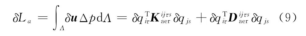
The differential pressure is a function of two contributions.The first is caused by the vertical velocity,while the second originates from the slope of the structure in the flow direction.The work due to the aerodynamic forces can be written as whereΛis the surface exposed at the air flow.The complete formulation has not been reported for sake of brevity.
3 Results
In this section are presented the results obtained by using the model introduced in the previous section.The complete aero-thermo-mechanical model is introduced step by step.The first analysis is devoted to the assessment of the mechanical model.Therefore the thermo-mechanical model is introduced.The last example is devoted to the aero-thermo-mechanical analysis of a VTI panel.
3.1 Mechanical buckling of a composite panel
A four-layer square panel is considered.The panel has a lateral dimension of 0.1mand a thickness of 0.002m.The panel is considered simply supported and the staking sequence of the lamination is[0/90/90/0].The mechanical properties are:E1=127.6×10+9Pa,E2=E3=11.3×10+9Pa,G12=G13=6.0×10+9Pa,G23=1.8×10+9Pa,ν12=ν13=0.3,ν23=0.36.A second-order layer wise model is used in the analyses.The critical stressσxxis investigated imposing a constant value ofσyy.
Fig.1shows the evolution of the critical load σxx-cr,at different preloadσyy.The results show that by increasing the preload,the critical load decreases as expected.The numerical results are reported in Table 2,where the reference value presented in Ref.[6]are also reported.

Fig.1 Evolution of the critical valueσxxat differentσyy preloads
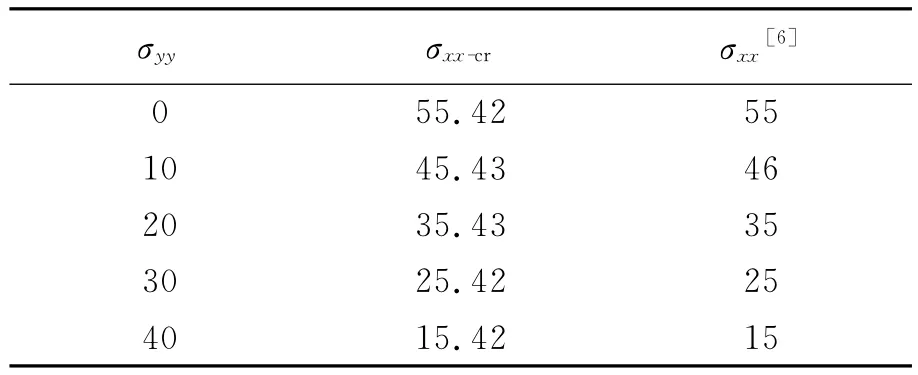
Table 1 Critical stress loadσxx-crat differentσyypreloads
3.2 Thermal buckling of a composite panel
In order to validate the thermo-mechanical solver,a five-layer composite panel with stacking sequence[θ/-θ/θ/-θ/θ]is considered.The reference test case presented in Ref.[6]uses a Ritz/Galerkin approach for evaluating the thermal buckling load and varying the fibers orientation.The panel has the following characteristics:length l=1m,width w=1m,h=0.01m,e1=40×10+9Pa,e2=e3=1×10+9Pa,G12=G13=0.6×10+9Pa,G23=0.5×10+9Pa,ν12=ν13=ν23=0.25,α1=2×10⁻⁸K-1,α2=2.25×10⁻⁵K-1.A second-order LW model is used in the analyses.
As expected,in correspondence ofθequal to 0or 90°,both results obtained using Galerkin and FEM approach,are in good agreement.Varying the fiber orientation,FEM formulation provides more conservative results.It is known that Ritz/Galerkin-based solvers,are less capable of correctly implementing the BCs for angle-ply thin structures.Fig.2shows critical temperature trends with both the approaches.
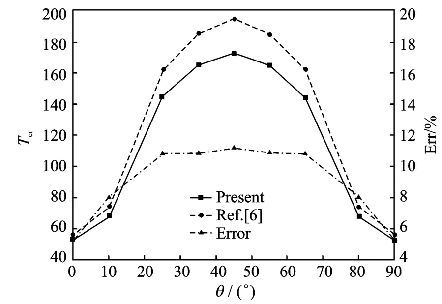
Fig.2 Critical temperatures vs lamination angles
3.3 Aero-thermo-mechanical analysis of VTI panel
Let us consider 1/3of cylinder arc length VTI sandwich panel.Characteristics of this con-figuration are:a=1.5m,b=3.12m,htot=0.012m,hl-skin=0.000 5m,hcore=0.01m,R=1.49m.Core-E=5.4×10+7Pa,G=2.3×10+7Pa,ν =0.173 9,ρ=80kg/m3,α=10-6K-1.Skins-E11=85.0×10+9Pa,E22=E33=1.5×10+9Pa,G12=G13=1.6×10+9Pa,G23=1.8×10+9Pa,ν12=ν13=0.3,ν23=0.45,α1=0.9×10-6K-1,α2=27.0×10-6K-1.
Since this analysis is used an LW theory of the second-order,it corresponds to 2 754degrees of freedom(Dofs).The panel is simply supported along the sides in the span-wise direction.The combined effects of curvature,thickness,and sandwich configuration provides an elevated momentum of inertia of the panel.So,this involves a very high critical temperature,for thermal buckling.The obtained results indicate that Tcr=17 080K,which is obviously unrealistic for any current application.Hence,the lower temperature is chosen.
Table 2shows the critical Mach numbers at different temperatures for a reference density of ρ=0.8kg/m3.The temperatures do not have significant effects on the aeroelastic behavior in terms of stability boundary.Applying higher thermal stress,expressed as a fraction of the critical temperature,results notify a relevant reduction of the stability margin,as shown in Table 3.
Fig.3shows the modal damping variation for different temperatures.
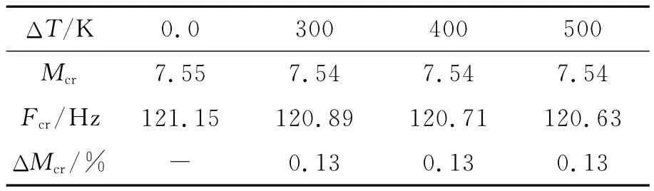
Table 2 Critical Mach number at different temperatureΔT

Table 3 Critical Mach numbers at different temperatures ΔT/ΔTcr

Fig.3 Modal damping evolution at different temperaturesΔT/ΔTcr
4 Conclusions
In this paper,an advanced 2Dmodel,deriver using the CUF is used to perform the aero-thermo-mechanical analysis of composite panels.The present aeroelastic model shows good agreement with the reference results.The higher-order formulation allows sandwich and composite materials to be investigated.The tests carried out for the VTI panel,shown the influence of the thermal loads on the flutter boundary.Typical operative conditions,with temperature in the operational range of the materials,entail a minimal reduction of the critical Mach,expressed in percentage,compared to the un-stressed condition.Future developments should be devoted to implement a thermal theory,which could represent thermal gradients along the thickness and correctly predict the in-plane stress related to pinched point constraints.
[1] Dixon S C,Shideler J L,Shore C P.Flutter at Mach 3of thermally stressed panels and comparison with theory for panel with edge rotational restraint[R].NASA-TN-D-D3498,1966.
[2] Noor A K,Burton W S.Computational models for high-temperature multilayered composite plates and shells[J].Applied Mechanics Reviews,1992,45(10):419-446.
[3] Khdeir A A.Thermoelastic analysis of cross-ply laminated circular cylindrical shells International Jou-rnal of Solids and Structures,1996,33(27):4007-4017.
[4] Carrera E.An assessment of mixed and classical theories for the thermal stress analysis of orthotropic multilayered plates[J].Journal Thermal Stress,2000,23(9):797-831.
[5] Carrera E.Temperature profile influence on layered plates response considering classical and advanced theories[J].AIAA J,2002,40(9):1885-1896.
[5] Wu Z,Chen W.A global-local higher order theory for multilayered shells and the analysis of laminated cylindrical shell panels[J].Composite Structures,2008,84(4),pp.350-361.
[6] Fazzolari F A,Carrera E.Thermo-mechanical buckling analysis of anisotropic multilayered composite and sandwich plates by using refined variable-kinematics theories[J].Journal of Thermal Stresses,2013,36(4):321-350.
[7] Cinfera M,Chinosi C,Della Croce L.MITC9shell elements based on refined theories for the analysis of isotropic cylindrical strucutures[J].Mechanics of Advanced Materials and Strucutures,2011.
[8] Ashley H,Zartarian G.Piston theory—A new aerodynamic tool for the aeroelastician[J].Composites Structures,1956:1109-1118.
[9] Carrera E,Brischetto S,Nali P.Plates and shells for smart structures:classical and advanced theories for modeling and analysis[M].[S.l.]:John Wiley &Sons,2011.
[10]Carrera E,Cinefra M,Petrolo M,et al.Finite element analysis of structures through unified formulation[M].[S.l.]:John Wiley &Sons,2014.
[11]Reddy J N.Mechanics of laminated composite plates and shells.Theory and Analysis[M].2nd Ed.[S.l.]:CRC Press,2004.
 Transactions of Nanjing University of Aeronautics and Astronautics2014年2期
- Transactions of Nanjing University of Aeronautics and Astronautics的其它文章
- Thin Film Lithium-Ionbatteries Crack Initiation Due to Thermal and Electric Effects
- Influence of Patch Side of Heat-Ray Absorbing Film on One-Dimensional Unsteady Thermal Stresses in Window Glass
- One-Dimensional-Unsteady Thermal Stress in Heat-Ray Absorbing Sheet Glass:Influence of a Sudden Weather Change
- General Solutions of Thermoelastic Plane Problems of Two-Dimensional Quasicrystals
- Temperature-Dependence of Microstructure Evolution in a Ferroelectric Single Crystal with Conducting Crack
- Problem of Circular Hole in Thermopiezoelectric Media with Semi-permeable Thermal Boundary Condition