
Panoram ic Imaging System Inspired by Insect Com pound Eyes*
2014-05-05 22:55XingQiang邢强WangHao王浩DaiZhendong戴振东
关键词:王浩
Xing Qiang(邢强),Wang Hao(王浩),Dai Zhendong(戴振东)*
1.Institute of Bio-inspired Structure and Surface Engineering,Nanjing University of Aeronautics and Astronautics,Nanjing,210016,P.R.China;2.College of Mechanical and Electrical Engineering,Nanjing University of Aeronautics and Astronautics,Nanjing,210016,P.R.China
1 Introduction
Visual navigation systems have many advantages,such as abundant information,autonomy,low cost,and reliability.They have become a hot research field for unmanned aerial vehicles(UAVs),deep space explorers,and underwater robot navigation[1,2].Traditional visual navigation systems aremainly developed for autonomous land robots.Their small view anglemakes it difficult tomeet the needs of three-dimensional space navigation and panoramic information acquisition.With the development of visual guiding in UAVs, moon exploration, and ocean exploration fields,visual systemswith a large field of view(FOV)and panoramic imaging capability are particularly important and attract the most attention.Analogously,in bionic systems compound eyes have a large FOV and high perception sensitivity in moving target detection,thus having a reasonable prospect of applying to military,medical,and aerospace areas[3].
A number of scholars have attempted to imitate the characteristics of compound eyes[4-9].There are threemain types of central projection imaging system for wide FOVs,namely,fisheye lens,micro-lens arrays,and ring rotation imaging systems.A fisheye lens is a super-wide-angle objective lens.It has a very short focal length,and image distortion.Fisheye lenses increase the edge distortion of an image by expanding the lens'FOV[4].Micro-lens imaging systems are often combined with the optical relay elements of fibers,aperture arrays,ormulti-channelmicro-lens arrays[5-9].They use a large area of single charge-coupled device(CCD),and have imaging characteristics of high synchronization with a wide FOV.However,the perspective of its scene information means that image details have a relatively low resolution.The ring image system adops a single CCD rotating around a fixed axis.Although this system is low cost with high resolution,it must continuously work to track moving objects.
To obtain an imaging system with a large viewing angle,high resolution,and small distortion,it is easy to implement a CCD camera array[10,11].However,how to deal with the multi-channel image data synchronization in real-time becomes a key technical problem.Using complex programmable logic device(CPLD)and audio-video receivers(AVR)to control the linear CCD array is a good way to improve the synchronization in real-time,avoiding large amounts of two-dimensional image data processing[12].With the development of embedded technology,advanced RISCmachines(ARM)is used for themulti-channel acquisition of temperature, force, and light data[13,14].Moreover,embedded systems can be used in a multi-channel monitoring system.Web/PC clients implement cameras through TCP/IP,and the client’s window shows the image transmission in motion joint photographic experts group stream (MJPEGSTREAM),paying no attention to the synchronization of slaves over every channel[15].
In this paper,using the function of ARM-based slave image acquisition and a server multi-thread method,authors develop a multi-channel image system with synchronous panoramic image acquisition and high-speed V4L2 video stream capture.
2 Design of Image Acquisition System
2.1 Hardware design of the system
The ARM consists of an S3C2440 CPU chip and peripheral interface circuits,which is a core part of the hardware design,as shown in Fig.1.The hardware circuit includes four USB ports,an Ethernet port chip,synchronous dynamic random access memory(SDRAM),and FLASH.The image data transmission utilizes universal serial bus(USB)and local area network(LAN)technologies.The system can be used inmobile robots for remote transmission of visual data.

Fig.1 Slave computer hardware structure
2.2 Software design of the system
The software program has different functions in slave and host computers.In the slave computer,the program is used to collect images,receive commands,and transmit synchronization images to the host.In the host computer,the program is used to send commands,receive images,and display image data.
2.2.1 Construction of slave computer
The slave computer is employed to collect images.It is developed using the standard C language and Linux-2.6.32.2 kernel operating system,with transplanted USB and a V4L2 driver.Itsmain functions are to capture multi-channel video/images and execute instructions from the host computer.The flowchart of themain program is shown in Fig.2.
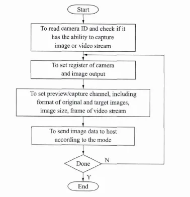
Fig.2 Acquisition procedure of video/frame images by USB camera
Based on the V4L2 camera device driver,one design the system to work in two modes[16].One is the Poll/Read mode:the slave computer controls the camera so as to collect images in the specified order.Using a non-blockingmode to obtain image data from the kernel is time-consuming and requires a lot of memory space to switch and copy byte-by-byte.However,it is a simple way to implementmulti-channel single-frame image acquisition.It can control the USB camera arrays to collect images and send static single-frame image sequences to the host computer server.In addition,information data describing the surrounding environment can be collected.The other is the video preview mode:the slave computer controls one camera to collect images,which is more suitable when the slave computer uses a single camera to capturemovement.
When observing“sensitive”objects in the video preview mode,the slave computer controls all USB cameras to capture images under the Poll/Read protocol.After obtaining these images,the host computer stitches the panoramic images together.
2.2.2 Control ofmulti-channel image acquisition
In the proposed system,authors use TCP for remote data transmission.On the slave side,the system creates a socket file descriptor to complete the TCP connection and receive/transmit data.On the host side,we create DevListen(·),DevSend(·),and DevRecv(·)threads to listen,send,and receive image data to a server port,respectively.
The architecture of the TCP/IP connection is shown in Fig.3.Firstly,the host reads the config.txt file when the slave sends a link request;secondly,the host checks the client's IP address and judges whether the request is legal;finally,the host establishes the connection with the slaves.After connecting to the TCP/IP transmission channel,image data is sent via the DevSend(·)thread,and received by the host’s DevRecv(·)thread in RFC1055 format.
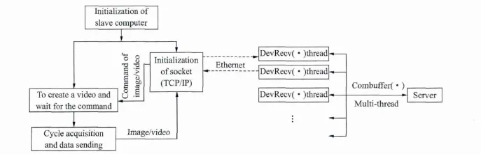
Fig.3 Workflow ofmulti-thread monitoring system based on TCP/IP
2.2.3 Control ofmulti-thread image stitching
A commonly used multi-channelmodel is shown in Fig.4(a)[13,14].The server issues the command to the slaves in the TCP/IP connection through the socket port.The slaves then capture images and send them to the server.The server only receives and shows the images over these channels,but does not solve the image transfer process in order.Thread A collects image sequence A1/A2/A3/… Ai.The uploaded images of thread A,B,C and Dmay be in the order A1/B1/C1/A2/B2/D1/D2/A3….If it is necessary to manage the collected images,they are commonly arranged by query process ID.
To achieve a synchronous panoramic image from multiple channels,the stitched sequence of the image must be synchronized.The collected image data is disordered by themodel in Fig.4(a).In the collected image sequence A1/B1/C1/A2/B2/D1/D2/A3,one should collect images A1/B1/C1/D1and stitch them together.If the model is used for continuous multi-image stitching,it will reduce the synchronization of panoramic image acquisition.
The model can capture multi-channel synchronous images successively,as shown in Fig.4(b).In themodel,the panoramic image stitching program is taken as themain-thread,while every slave connected by TCP is considered to be one child-thread in the thread pool[17].With the above setting,the childthreadswill not appear as omissions and duplications in the process of image stitching.Themodel succeeds in collecting the image from each thread synchronously,and then performs the next command.To achieve the function of the model,two problems must be solved.One is the synchronization between the main thread and child-threads,and the other is the mutex in child-threads.

Fig.4 Threadingmodel ofmulti-channel image acquisition
In the multi-thread management,the “Event”has the advantage of synchronization between themain thread and child-threads,and the“signal lock”and“critical region”are more effective in controlling the mutex of child threads,as shown in Fig.5.

Fig.5 Flowchart ofmutex and synchronization of multithreading program
To regulate the data transmission,authors add the timer DevTimer(·)and the state machine Dev-Core(·).By setting amutex or public semaphore in the program,one can ensure that the read and write threads work at the same time.The details of the procedure are shown in Fig.6.In thisway,the hostmachine is protected against the accidental loss of data caused by logical confusion.

Fig.6 Synchronization test for two image cameras
2.3 Synchronization test for image acquisition system
LED lights are designed to test the system synchronization.The test procedure is as follows:
(1)To use MCU to control the LED diode array to flash in a fixed time interval;
(2)Twenty LEDs light and extinguish in order;
(3)The host computer controls the slave computers to take pictures.The image acquisition diagram is shown in Fig.6.
Multiple images are taken in the Poll/Readmode with a V4L2 video stream.The results show that the cameras can realize 10 f/s video capture in the V4L2 video mode,and 10 ms imaging synchronization in the Poll/Read mode.
3 Result Discussion
In this experiment,authors use 16 small USB cameraswith an image size of 640 pixel×480 pixel and a frame rate of15 f/s,arranged as shown in Fig.7(a).To ensure that the annular CCD array do not cause large deflections or pitch,it is fixed on an 80 mm positioning structure.Under the control of the host software,the slave computer collects the circular images as shown in Fig.7(b).While collecting a video stream,the system can obtain multi-channel images.
Compared with the scale-invariant feature transform(SIFT)panorama stitching algorithms,continuous stitching overlay graphicswill lead to deformation,though it can be adjusted by automatic straigh-tening,as shown in Figs.7(d,e)[18].The automatic straightening algorithm will increase the computational complexity of the system.To improve the speed of panorama stitching,neighboring pictures should have only a translational relationship in the overlapping area[19].The phase correlation method of stitching the images directly is better[20].The panoramic image is shown in Fig.7(c).A better association between the images will help improve the image stitching speed.
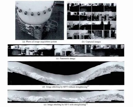
Fig.7 System and 360°panoramic images
4 Conclusions
In terms of its hardware design,the proposed system allows different USB cameras to be selected for the remote transmission of images.Functionally,the system achieves the synchronization of captured photos in 10 ms,and matches video streams at 10 f/s.By addingmachine storage and embedded image processing,the system can realize the intermittent timing transmission of“sensitive”images.The proposed system is also energy efficient and stealthy.
Compared with annular rotating panoramic imaging systems,the AMR-embedded system has an advantage of continuous tracking of moving targets in time.It can easily be connected to USB cameras,and meets the need of long-distance data transmission via LAN.Thus,the proposed system has advantages of convenient software migration,easy hardware upgrades,a short production cycle,and low production cost.
[1] Huang Xianlin,Jiang Xiaonan,Lu Hongqian,et al.Survey of vision for autonomous navigation[J].Journal of Jiling University:Information Science Edition,2010,23(2):158-163.(in Chinese)
[2] Guo Li,Ang Haisong,Zheng Xiangming.Monocular vision based motion estimation of indoor micro air vehicle and structure recovery[J].Journal of Nanjing University of Aeronautics and Astronautics,2012,44(2):165-171.(in Chinese)
[3] Lu Liming,Wang Guofeng,Zhang Ke,et al.Research onmulti-modemissile based on ommateum[J].Infrared Technology,2001,23(5):9-10.(in Chinese)
[4] Feng Weijia,Zhang Baofeng,Zhu Junchao,et al.Research on an embedded omnidirectional vision navigation[J].Journal of Optoelectronics Laser,2011,22(8):1147-1152.(in Chinese)
[5] Tanida J,Kumagai T,Yamada K,et al.Thin observationmodule by bound optics(TOMBO):Concept and experimental verification[J].Appl Opt,2001,40(11):1806-1813.
[6] Horisaki R,Tanida J.Preconditioning formulti dimensional TOMBO imaging[J].Optics Letters,2011,36(11):2071-2073.
[7] Zhu Difeng,Zeng Xuefeng,Li Chenhui,et al.Focustunablemicrolens arrays fabricated on spherical surfaces[J].Journal of Microl-electromechanical Systems,2011,20(2):389-395.
[8] Li Lei,Yi AY.Development of a 3D artificial compound eye[J].Opt Express,2010,18:18125-18137.
[9] Zhang Hao,Li Lei,David LM,et al.Development of a low cost high precision three layer 3D artifical compound eye[J].Optics Express,2013,21(19):22232-22245.
[10] Ji Zhen,LiQi,Zhang Jihong.Image panoramicmosaicing with global and local registration[J].Transactions of Nanjing University of Aeronautics and Astronautics,2001,18(1):68-74.
[11]Thierry M.Vision system dedicated to panoramic three dimensional scene reconstruction[J].Journal of Electronic Imaging,1998,7(3):672-676.
[12] Wang Yongsong,Hao Qun,Song Yong,et al.An ommidirectional target monitoring system based on compound eyes technology[J].Optical Technique,2006,32(Suppl):158-161.(in Chinese)
[13] Li Na.FPGA based real-time video image acquisition and storage system[J].Transactions of Nanjing University of Aeronautics and Astronautics,2012,29(4):404-410.
[14] Li Bo.Design and realization ofmulti-channel data collection implement based on ARM[D].Harbin,China:Harbin Engineering University,2011.(in Chinese)
[15]Alkar A Z,Karaca M A.An internet-based interactive embedded data-acquisition system for real-time applications[J].IEEE Transactions on Instrumentation and Measurement,2009,58(3):522-529.
[16] Chen Mingjie,Gu Guohua,Chen Qian,et al.A multichannel CCD data processing and transmission system based on FPGA[J].Infrared Technology,2013,35(3):161-165.(in Chinese)
[17]Jefferey R,Christophe N.Windows Via C/C++[M].Beijing:Tsinghua University Press,2008.
[18] Matthew B,David G L.Automatic panoramic image stitching using invariant features[J].International Journal of Computer Vision,2007,74(1):59-73.
[19] Wang Zhihe,Shu Rong,He Zhiping,et al.New method of CCD camera calibration based on collimator[J].J Infrared Millim Waves,2007,26(6):465-468.
[20]Benson J B,Wright C H,Barrett S F.Redesign and construction of an artificial compound eye visual sensor[J].ISA Biomed Sci Instrum,2008,44:367-372.
猜你喜欢
少儿美术·书法版(2021年7期)2021-10-20
作文大王·低年级(2018年5期)2018-06-20
作文大王·低年级(2018年4期)2018-05-24
Defence Technology(2011年4期)2011-07-25
私蜜(2009年2期)2009-03-25
 Transactions of Nanjing University of Aeronautics and Astronautics2014年3期
- Transactions of Nanjing University of Aeronautics and Astronautics的其它文章
- Experiment on Adiabatic Film Cooling Effectiveness in Front Zone of Effusion Cooling Configuration*
- Analysis for Transm ission of Com posite Structure w ith Graphene Using Equivalent Circuit M odel*
- Control System in M issiles for W hole-Trajectory-Controlled Trajectory Correction Projectile Based on DSP
- Geometric Covariance Modeling for Surface Variation of Compliant Parts Based on Hybrid Polynomial Approximation and Spectrum Analysis*
- Fast SSED-MoM/FEM Analysis for Electromagnetic Scattering of Large-Scale Periodic Dielectric Structures*
- Focus Reflective Shock Wave Interaction with Flame