
Numerical simulation of hull/propeller interaction of submarine in submergence and near surface conditions*
2014-06-01 12:29ZHANGNan张楠ZHANGShengli张胜利
水动力学研究与进展 B辑 2014年1期
ZHANG Nan (张楠), ZHANG Sheng-li (张胜利)
China Ship Scientific Research Center, Wuxi 214082, China, E-mail: zn_nan@sina.com
Numerical simulation of hull/propeller interaction of submarine in submergence and near surface conditions*
ZHANG Nan (张楠), ZHANG Sheng-li (张胜利)
China Ship Scientific Research Center, Wuxi 214082, China, E-mail: zn_nan@sina.com
(Received December 1, 2012, Revised March 2, 2013)
Hull/propeller interaction is of great importance for powering performance prediction. The features of hull/propeller interaction of a submarine model with a high-skew five blade propeller in submergence and near surface conditions are numerically simulated. The effect of propeller rotation is simulated by the sliding mesh technique. Free surface is captured by the volume of fluid (VOF) method. Computed results including resistance, thrust, torque and self-propulsion factor are compared with experimental data. It shows fairly good agreement. The resistance and wave pattern of the model at different depths of submergence are computed. And the thrust, torque and self-propulsion factor of the model in submergence and near surface condition are compared to analyze the effect of free surface on self-propulsion performance. The results indicate that free surface has more influence on resistance than that on self-propulsion factors.
submarine, hull/propeller interaction, numerical simulation, sliding mesh, volume of fluid (VOF) method
Introduction
The simulation of hull/propeller interaction is of great interest to ship design community for powering performance analysis. In this field, the key requirement is an accurate prediction of the forces acting on the hull with appendages and propeller. There are two traditional approaches to estimate the hydrodynamic characteristics of ship with propeller, i.e., the hull/ propeller interaction. One is a semi-empirical theoretical approach which only requires information about the geometry of ship with propeller and operating condition. The other is more reliable and long-standing approach which is model test carried out in towing tanks.
Computational fluid dynamics (CFD) has been developed rapidly in capability and practicality during past years. Potential flow methods are used regularly. Viscous methods using the Reynolds-averaged Navier-Stokes (RANS) model, are rapidly becoming feasible with the development of computational resources, and the accuracy is improved. Scale-model tests usually provide resistance and powering curves, which are difficult for providing detailed data in important regions. Computations provide the flow field that could help researchers understand the hull/propeller development process. Now CFD is considered as a fast and robust tool in modern ship design stage. It is also an important approach for investigating the physics of complex flow phenomena around ships and underwater vehicles. Today, numerical simulation tools are continuously developed and increasingly used. The development of numerical methods and high-performance computing technology mean that CFD methods have matured to calculate the flow around realistic geometries of ship and underwater vehicle. A combination of model test and computation is the best approach in the ship hydrodynamics field, and should be promoted even further.
The research on numerical simulation of viscous flow field of submarine has been widely carried out in past decades. Most of them were focus on submergence condition without considering free surface. Bull[1]simulated the viscous flow around SUBOFF AFF-1 and AFF-8 configurations with different flow solvers, turbulence models and grid topologies. The capability of the CFD approach to the prediction of nominal wake has been quantified by comparison with experimental data. Hyams and Sreenivas[2]computed the axial forces, normal forces and pitching moments atseveral angles of attack of SUBOFF hull by using S-A and qω- turbulence models. Zhang et al.[3]computed the resistances and flow fields of two submarine models SUBOFF and CSSRC SM-x by solving RANS equations with the kε-, RNG kε- and kω- turbulence models. The wake distributions of sail with fillet and stern appendages with fillets were predicted and mechanism of flow around fillet was studied from the viewpoint of vorticity.
McDonald and Whitfield[4]used the code Navier-Stokes/6-DOF to study the trajectory prediction of two kinds of fully appended self-propelled submarines, one with a body-force propeller and the other with an actual rotating propeller. Cash[5]examined the hull/ propeller interaction of fully submerged submarine model. With the exception of the bare hull configuration, all simulations resulted in solutions with excellent agreement to experimental data, which showed that the flow solver U2NCLE could lead to valid results for forward propelled and crashback submarine simulations. Pankajakshan et al.[6]confirmed the validation of numerical simulation for submarine hull/propeller interaction using the CFD code U2NCLE. Alin et al.[7]investigated the effect of propeller by an actuator disc model for SUBOFF AFF8 case, and both “towed” and“self-propelled” conditions were analyzed.
Nowadays computations of viscous turbulence flow around submarine without consideration of the free surface have been widely conducted to predict the wake distribution and the hydrodynamic forces. But the free surface effect on flow around submarine is an important and interesting problem. Griffin[8]developed a method for coupling a RANS computer code with an inviscid panel code to predict the maneuvering characteristics of submarines operating near the free surface. Five submarine geometries operating at five depths, seven Froude numbers and several pitch angles have been considered to obtain the relationships between these parameters and the vertical force and pitching moment on the bodies. Yang[9]studied the viscous flow around a submarine operating near the free surface, and gave the related wave patterns. Dawson et al.[10]made an experimental investigation into the wave making resistance of an appended submarine operating near the free surface. Two model configurations, bare hull with and without the sail, were towed in a straight line at zero angle of incidence for a range of depths and speeds. The results showed increased resistance for both configurations at shallow depths when compared to the deep-water one. Renilson et al.[11]identified the effects of depth and speed on the submarine resistance increment caused by operating close to the free surface. The models were tested over a range of depths and speeds, and the resistances at shallow depths were compared with the deep-water ones. Renilson and Ranmuthugala[12]studied several operational factors which influence the wave making resistance and the vertical forces and moments. These factors included the submergence depth, forward speed, size and configuretion of the appendages, and the length to diameter (/)L D ratio. A series of captive model experiments were conducted to quantify these effects. They also computed the SUBOFF geometry at different /L D ratios and Froude numbers by using the RANS approach to determine the influence of these parameters.
Zhang et al.[13,14]computed the flow fields around a submarine moving on and near the free surface. Computed results, including resistances and wave patterns, were analyzed. Zhang et al.[15]studied hull/propeller interaction of SUBOFF in near-surface condition. The SUBOFF with a traditional five-blade propeller was adopted, which was a hypothetical submarine model. The geometries of SUBOFF and the traditional five-blade propeller are simple, so it is an initial research of hull/propeller interaction in nearsurface condition, and the computation accuracy needs to be improved.
The above-mentioned works are valuable for simulating the hull/propeller interaction of submarine. In the present paper, the numerical simulations of hull/ propeller interaction of a submarine model which has a realistic geometry in submergence and near-surface conditions are presented. The model is a benchmark model at the CSSRC for validating the related CFD techniques. The propeller is a high-skew five-blade propeller, so the technical problem is more difficult than that in Ref.[15].
1. Computational method
Both water and air are assumed to be incompressible and isothermal Newtonian fluids. Flow is threedimensional and turbulent. The continuity equation and RANS equations can be written in Cartesian tensor notation as
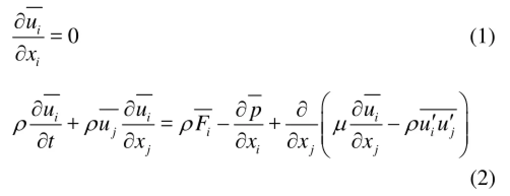
where uiis the mean velocity component, and ui' is the fluctuating velocity component (i=1,2,3).
The volume of fluid (VOF) method is adopted in simulating the free surface flow. The VOF algorithm was designed to capture discontinuous layer. It introduces a volume fraction of fluid as an additional dependent variable. In this method, αidenotes the ithfluid volume fraction in the cell. It is used to determine the position and shape of interface. For twophase flow, the continuity equation includes both phases (water and air). Mass for each phase will be conservative. The tracking of the interface between the two phases is accomplished by the solution of a continuity equation for the volume fraction. For the water, this equation has the following form

where the subscriptwdenotes the water andadenotes the air.
The renormalization group (RNG)kε- turbulence model is used in the present study.
The boundary conditions are composed of the following:
At inlet boundary, velocity and volume fraction is prescribed.
At outlet boundary, hydrostatic pressure is set.
At outer boundary, velocity and volume fraction is prescribed.
Symmetry boundary which is only used in the towed condition (resistance computation), zero normal velocity and zero normal gradients of all variables are set.
At wall boundary, the wall function is introduced.

Fig.1 Computation domain
Figure 1 shows the computational domain, whereLis the length of submarine andDis the diameter of propeller.
The effect of propeller rotation is simulated by sliding mesh method. The hub and blades of propeller are rotating solid walls. The block boundaries where rotational and stationary surfaces are coincident are defined as interfaces to keep connectivity. Figure 2 shows the sketch of sliding mesh method.
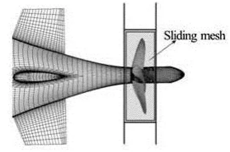
Fig.2 Sketch of sliding mesh method
The differential equations are discretized by the finite volume method. For convection term, the second-order upwind difference scheme is applied. For diffusion term, the central difference scheme is applied. The velocity-pressure coupling is based on the SIMPLE algorithm and algebraic multigrid method is employed to accelerate the solution convergence. The time step is 0.001 s.
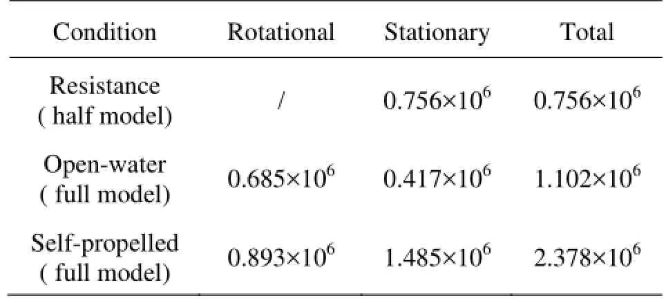
Table 1 Numbers of cells in the computations
2. Geometry and mesh
The numerical simulation of hull/propeller interaction of model SubM01 with ProM01 is carried out in the present paper. SubM01 is one of the benchmark submarine series with a lengthL≈5 m. The highskew propeller model ProM01 has five blades with the diameter of 0.2 m. It belongs to the hypothetical propeller series models for submarines. Experimental investigations have been made for this hull and propeller in the CSSRC, which are suitable for validation of CFD code and verification of numerical results. The numbers of cells used in resistance, open-water, selfpropulsion conditions are shown in Table 1, which have been validated by grid convergence studies. Figure 3 illustrates the grids on the submarine and propeller surfaces. All the computational cases are discretized by structured cells.
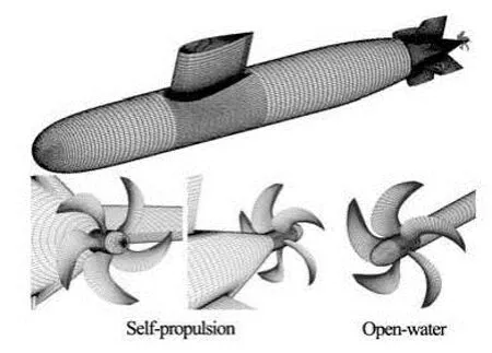
Fig.3 Grids on the surfaces of SubM01 and ProM01
3. Results and discussion
3.1Submergence condition
The thrust identity method is adopted to analyze the performance of hull/propeller interaction and selfpropulsion factors. So the resistance of submarine, the thrust/torque of propeller in open-water condition and the forces of submarine with propeller in self-propulsion condition are required.

Fig.4 Comparison between measured and computed results for total resistance coefficient in submergence condition
Firstly, the resistance of submarine model SubM01 in submergence condition at different Reynolds numbers,Re≈2× 10⁷-5× 10⁷(based on the hull length), are computed. The calculated total resistance coefficients (Ct) are shown in Fig.4 and compared with the experimental data. Overall variation tendency and magnitude of the total resistance coefficient is well predicted. The computational accuracy is within 2.0%-3.1% in comparison with measurements and the relative error decreases asReincreases. The Reynolds numbers adopted in numerical simulation are the same as that in experiment. It indicates that the computational accuracies are different for different Reynolds numbers, the accuracy at high speed is better than that that at low speeds because the full developed turbulence simulation is used in CFD. In tests, there are laminar and transition disturbances in low speed. Lots of past researches validated the phenomenon.
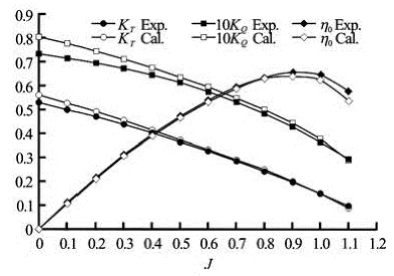
Fig.5 Comparison between measured and computed performance coefficients of propeller
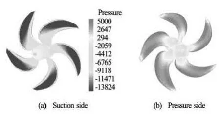
Fig.6 Distribution of pressure on the surface of ProM01
Secondly, the thrust and torque of propeller model ProM01 in open-water condition are computed. In open-water tests, the axial inflow is varying and the propeller rotational speed is kept constant, and the thrust/torque of propeller are measured. Computations are performed under the same condition. Figure 5 compares the computed performance coefficients with the experimental data at the advanced number 0-1.1. The differences are about 1%-6% from measurements in the prediction of thrust coefficient (KT). The torque coefficient (KQ) is over-predicted about 2%-10%. The computational accuracy of torque is worse than that of thrust, because the thrust is mainly gained by pressure integral which is insensitive toy+, while the torque is mainly gained by shear stress integral which is sensitive toy+. And the magnitude of torque is very small compared with thrust, 10KQis the same order of magnitude asKT. In the condition ofJ=0 (i.e., in moored condition), the low relaxation factor and small time step is required to achieve the convergence. In particular,KTandKQare predicted very accurately at the advance number 0.4-1.0, and the computational difference compared with measurement is within 3%. For other advance numbers, the difference is a little larger but reasonable, and the thrust isbetter predicted. The computed open-water efficiency agrees well with the experimantal results, and the relative error is within 1%-3%. It is beneficial to the powering performance prediction. Figure 6 shows the pressure distribution on the surface of propeller.
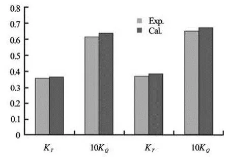
Fig.7 Comparison between measured and computed performance coefficients at two self-propulsion points
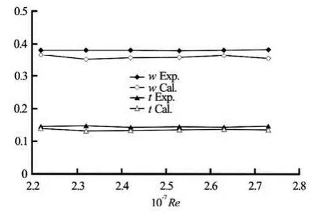
Fig.8 Comparison between measured and computed self-propulsion factors

Fig.9 Distribution of pressure on the surface of SubM01 with ProM01 in self-propulsion condition
Finally, the forces of submarine with a propeller in self-propulsion condition are computed. In self-propulsion tests, the axial inflow is invariable, the propeller rotational speed is changed for every towing speed, and six towing speeds are adopted. Computations are performed under the same condition. Figure 7 compares the computed performance coefficients at two selfpropulsion points with the experimental data. The differences are about 4%-6% from measurements in the prediction ofTKandQK. The comparison between measured and computed effective wake fraction and thrust deduction are showed in Fig.8. Distribution of pressure on the surface of model in self-propulsion condition is presented in Fig.9.
By comparing computed results with experimental data, it indicates that numerical approach is creditable to predict the resistance, thrust and torque. So the numerical simulation method to analyze the hull/ propeller interaction of submarine is validated.
3.2Near surface condition
The application of CFD to study the resistance and hull/propeller interaction of a submarine in nearsurface condition is the topic under discussion here.
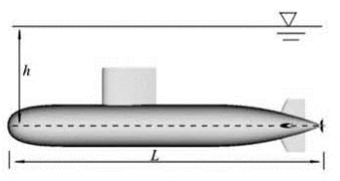
Fig.10 Sketch of submarine operating near free surface
In the condition of a submarine operating near the free surface, the depth of submergencehrepresents the distance from the axis of submarine hull to the still water level, as shown in Fig.10. The changes of resistance and wave pattern with the depth of submergence are investigated. The resistance and free surface flow at different depths of submergence, i.e.,h/Lof 0.2, 0.25, 0.3, 0.35, are simulated respectively. Computations are carried out at the Froude number (Fr) of 0.17-0.38, and only the calculation atFrof 0.35 are presented in this paper.Fris based on the hull length.
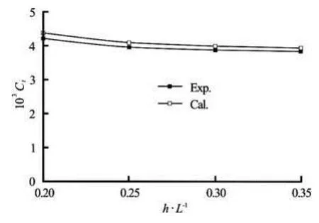
Fig.11 Comparison between measured and computed total resistance coefficient in near-surface condition
The computed total resistance coefficients for different depths of submergence are shown in Fig.11. It shows that the computed resistance coefficients of submarine operating near the free surface agree well with experimental results. Compared with the resistance coefficient in unbounded flow, the computed resi-stance coefficient incrementstCΔ at different depths of submergence are shown in Fig.12. The resistance of wave making decreases as the depth of submergence increases. It indicates that the free surface has a negligible effect on the resistance as long as the depth of submergence is greater than 1/3 submarine length.
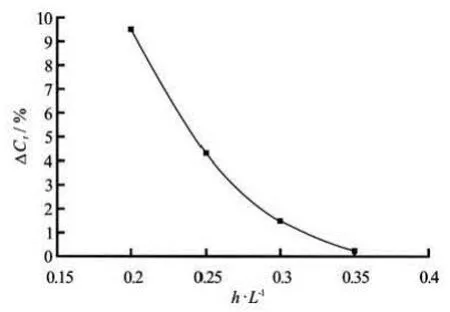
Fig.12 Resistance coefficient increments at different depths of submergence
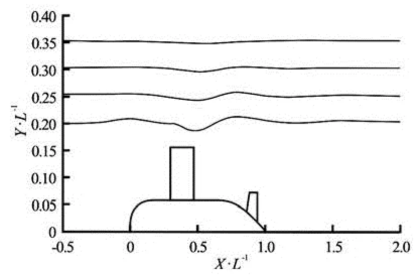
Fig.13 Wave profiles in symmetry plane at different values of h/ L
The simulated wave profiles in symmetry plane are shown in Fig.13 and the wave patterns at different depths of submergence are shown in Fig.14. Computed results indicate that significant wave occurs in the vicinity of the sail. The wave decays rapidly far from the stern.
The wave amplitude caused by submarine decreases as the depth of submergence increases as shown in Fig.13. There is not a significant wave profile at /h Lof 0.35. The phenomenon is also evident in Fig.14. There is an obvious wave around sail. So the sail is an important source of wave making. The wave height around sail is about 5%Las the /h Lis 0.2, and when the /h Lof 0.3, the wave height decreased to 0.2%L. It indicates that there is no significant wave when the depth of submergence is greater than 1/3 submarine length.
The simulated wave pattern in self-propulsion condition is shown in Fig.15. The comparison between self-propulsion factors in submergence and near-surface condition (h/L=0.2) is presented in Fig.16.
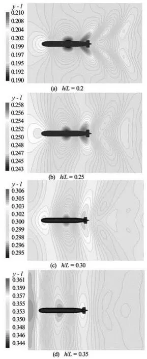
Fig.14 Wave patterns at different depths of submergence (worm’s-eye view)
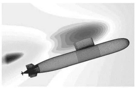
Fig.15 Wave patterns of self-propulsion submarine in near-surface condition
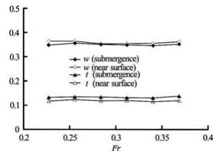
Fig.16 Comparison between self-propulsion factors in submergence and near-surface condition (h/ L=0.2)
We can find that the wave pattern of “self-propelled” submarine operating close to the free surface is different from that of “towed” submarine without propeller. The wave crest and tough are shifted to the stern under the influence of propeller rotation.
According to the procedure for the open-water test, the propeller immersion has to be selected such that air drawing from the water surface is avoided in any test condition. As a guide line, an immersion of the propeller shaft of at least 1.5Dis recommended. In this paper, the minimum /h Lis 0.2, and the immersion of propeller shaft is 5D, so the free surface effect can be ignored, which is validated by Fig.16. The difference of self-propulsion factor of submergence and near-surface condition is small from the viewpoint of powering performance prediction.
4. Conclusions
The RANS simulation of hull/propeller interaction of a submarine model with a propeller in submergence and near surface condition is presented. Compared with the experimental data, the numerical simulation reaches the reasonable accuracy for engineering purpose.
In near-surface condition, the free surface has a negligible effect on resistance and wave pattern as long as the depth of submergence is greater than 1/3 submarine length. The sail is an important source of wave making as it is the biggest appendage of submarine and close to the free surface. The variation of self-propulsion factors is small in near-surface condition compared with that in submergence condition.
In the future, it is necessary to carry out the study on more submarine models for the CFD verification, validation and new hull form design.
[1] BULL P. The validation of CFD predictions of nominal wake for the SUBOFF fully appended geometry[C]. Proceedings of 21st Symposium on Naval Hydrodynamics. Trondheim, Norway, 1996, 160-175.
[2] HYAMS D., SREENIVAS K. An unstructured multielement solution algorithm for complex geometry hydrodynamic simulations[C]. Proceedings of 23rd Symposium on Naval Hydrodynamics. Val de Reuil, France, 2000.
[3] ZHANG Nan, SHEN Hong-cui and YAO Hui-zhi. Validation of numerical simulation on resistance and flow field of submarine and numerical optimization of submarine hull form[J]. Journal of Ship Mechanics, 2005, 9(1): 1-13(in Chinese).
[4] MCDONALD H., WHITFIELD D. Self-propelled maneuvering underwater vehicle[C]. Proceedings of 21st Symposium on Naval Hydrodynamics. Trondheim, Norway, 1996, 478-489.
[5] CASH A. N. Computational studies of fully submerged bodies, propulsors, and body/propulsor interactions[D]. Master Thesis, Starkville, Mississippi, UK: Mississippi State University, 2001.
[6] PANKAJAKSHAN R., REMOTIGUE M. G. and TAYLOR L. K. et al. Validation of control-surface induced Ssbmarine maneuvering simulations using U2NCLE[C]. Proceedings of 24th Symposium on Naval Hydrodynamics. Fukuoka, Japan, 2002.
[7] ALIN N., BENSOW R. E. and FUREBY C. et al. Current capabilities of DES and LES for submarine at straight course[J]. Journal of Ship Research, 2010, 54(3): 184-196.
[8] GRIFFIN J. M. Numerical prediction of the maneuvering characteristics of submarine operating near the free surface[D]. Doctoral Thesis, Cambirge, Massachusetts, USA: Massachusetts Institute of Technology, 2002.
[9] YANG C. The future of CFD in hydrodynamics-Prediction and optimization[C]. Proceedings of the Conference of Global Chinese Scholars on Hydrodynamics. Wuxi, China, 2004, 60-73.
[10] DAWSON E., ANDERSON B. and Van STEEL S. C. et al. An experimental investigation into the effects of near-surface operation on the wave-making resistance of SSK type submarines[C]. Proceedings of MAST 2010. Rome, Italy, 2010, 1-8.
[11] RENILSON M. R., RANMUTHUGALA S. and DAWSON E. et al. Hydrodynamic design implications for a submarine operating near the surface[C]. Proceedings of Warship 2011: Naval Submarines and UUVs. Bath, UK, 2011, 1-7.
[12] RENILSON M. R., RANMUTHUGALA S. D. The effect of proximity to free surface on the optimum length/ diameter ratio for a submarine[C]. Proceedings of the First International Conference on Submarine Technology and Marine Robotics (ICSTaMR 2012). New Delhi, India, 2012.
[13] ZHANG N., SHEN H. and YAO H. et al. Numerical simulation of flow around submarine under full surface and submerged conditions[C]. The 5th Osaka Colloquium on Advanced Research on Ship Viscous Flow and Hull Form Design by EFD and CFD Approaches. Osaka, Japan, 2005.
[14] ZHANG Nan, SHEN Hong-cui and YAO Hui-zhi. Numerical simulation of flow around submarine operating close to the bottom or near surface[J]. Journal of Ship Mechanics, 2007, 11(4): 498-507(in Chinese).
[15] ZHANG Nan, ZHANG Sheng-li and SHEN Hong-cui et al. Numerical simulation of hull/propeller interaction with free surface[J]. Chinese Journal of Hydrodynamics, 2012, 27(1): 127-132(in Chinese).
10.1016/S1001-6058(14)60006-8
* Biography: ZHANG Nan (1977-), Male, Ph. D., Senior Engineer
猜你喜欢
美与时代·城市版(2022年3期)2022-04-25
环球时报(2022-04-02)2022-04-02
考试与评价·七年级版(2021年5期)2021-08-14
辽金历史与考古(2021年0期)2021-07-29
文化产业(2020年29期)2020-12-09
疯狂英语·新悦读(2019年11期)2019-12-18
电影文学(2019年6期)2019-11-15
NBA特刊(2018年21期)2018-11-24
中学生百科·大语文(2018年4期)2018-06-13
岷峨诗稿(2017年4期)2017-11-25

- 水动力学研究与进展 B辑的其它文章
- Deepwater gas kick simulation with consideration of the gas hydrate phase transition*
- Estimation of discharge and its distribution in compound channels*
- Influences of soil hydraulic and mechanical parameters on land subsidence and ground fissures caused by groundwater exploitation*
- A hybrid DEM/CFD approach for solid-liquid flows*
- An ocean circulation model based on Eulerian forward-backward difference scheme and three-dimensional, primitive equations and its application in regional simulations*
- Scale analysis of turbulent channel flow with varying pressure gradient*