
In-situ Observation of the Growth of Fibrous and Dendritic Crystals in Quasi-2-dimensional Poly(ethylene oxide) Ultrathin Films*
2014-07-24 15:40ZHOUYuanHANXiaLIUHonglai刘洪来andHUYing
ZHOU Yuan (周 圆), HAN Xia (韩 霞), LIU Honglai (刘洪来) and HU Ying (胡 英)
Key Laboratory for Advanced Materials and Department of Chemistry, East China University of Science and Technology, Shanghai 200237, China
In-situ Observation of the Growth of Fibrous and Dendritic Crystals in Quasi-2-dimensional Poly(ethylene oxide) Ultrathin Films*
ZHOU Yuan (周 圆), HAN Xia (韩 霞)**, LIU Honglai (刘洪来) and HU Ying (胡 英)
Key Laboratory for Advanced Materials and Department of Chemistry, East China University of Science and Technology, Shanghai 200237, China
Crystal growth processes of poly(ethylene oxide) were followed from the original nucleation sites by using atomic force microscopy. Two distinct quasi-2-dimensional crystals about 4 nm thick were obtained from as-spun polymer ultrathin films: fibrous crystals, generated by the shearing field via spin-coating, coexist with conventional dendrites. The growth of the two structures is dominated by diffusion limited aggregation, though the growth rate of the fibrous crystals is around one order of magnitude faster than that of the dendrites. The fibrous crystals are more stable than the dendritic ones.
polymer crystallization, crystal pattern formation, atomic force microscopy, poly(ethylene oxide)
1 INTRODUCTION
Poly(ethylene oxide) (PEO) has a simple chain structure with a low melting temperature, which makes it an ideal model for studying the morphology of semicrystalline polymers. The morphological behavior of PEO has been extensively studied and is well-understood. In general, polymer chains fold back and forth to form lamellae, further organizing to spherulites in the isotropic melt [1-3]. Under confinement, however, the isotropically growth is hampered and quasi-two-dimensional (quasi-2D) crystals form [4-10]. Typical quasi-2D geometries of PEO are always fractal patterns such as dendrite and seaweed, dominated by the diffusion limited aggregation [4, 5]. On the other hand, fibrous crystals can be generated by shearing and stretching. Limited by the processing methods, current studies on shear induced crystallization are mostly in the melt [11]. Little has been published with respect to the orientated crystallization under nanometer confinement, which is important for potential applications of nanofibers and nanowires. For this purpose, spin-coating may be an easy method. It is one of the most commonly used casting methods to obtain very thin and controllable film thickness. In addition, a shearing and stretching field can be generated to orientate flexible polymer coils during the casting process, which has been proved by various polymers [12, 13]. In this work, we use spin-coating to achieve two quasi-2D PEO crystal structures in ultrathin films: a conventional dendrite and a shearinduced fibrous crystal. Their crystallization processes on the nanometer scale are followed in-situ by the atomic force microscopy (AFM) from the original nuclei to observe the growth of both polymer crystals and growth rates. The possible origin of crystal growth patterns is discussed.
2 EXPERIMENTAL
2.1 Materials
Poly(ethylene oxide) (PEO) (Mw=9000−12500 g·mol−1) and Pluronic F127, poly(ethylene oxide)-poly(propylene oxide)-poly(ethylene oxide) (PEOPPO-PEO) (Mw=12500 g·mol−1with 30% PPO), were used as received.
2.2 Sample preparation
Samples were deposited onto freshly cleaved mica surfaces by spin coating from 4.0×10⁻⁴-4.0×10⁻⁵g·ml−1dilute benzene solutions at 4000-8000 r·min−1. The polymer then crystallized at ambient condition with the room temperature kept at around 15 °C.
2.3 Atomic force microscopy
The polymer crystallization processes were followed in-situ by AFM immediately after spin-coating. The AFM topography images were obtained by a tapping mode AFM (AJ-III, Aijian nanotechnology Inc., China) with a triangular micro fabricated cantilever (Mikro Masch Co., Russia) mounted with a Si tip of a length of 100 µm without coating and a spring constant of 48 N·m−1. The measurements were carried out at ambient condition at around 15 °C.
3 RESULTS AND DISCUSSION
In contrast to the formation of spherulites in thick films, which happens in minutes, the crystallization of quasi-2D geometries in ultrathin films starts at surfacenucleation sites with long induction periods usually several hours. However, most of the observations focus merely on the evolution of crystal morphology rather than from the very beginning of nucleation because the latter could be very difficult to monitor. In this work, we observe that the onset of the crystallization starts at some 10 h after spin-coating. As shown in Fig. 1 (a), three dots A, B, and C present 640, 950, and 600 nm in dimension and 20, 19 and 14 nm in height, respectively. Their lateral dimensions are much larger than that of the embryos in the previous work, which is smaller than 10 nm [14]. Despite the slight drift during AFM scanning, it is evident in the following images [Fig. 1 (b, d)] that the 2D crystals are originated from the nucleation sites A and B. Dot C finally fails to be a nucleus, quickly depletes and diffuses to the growth front of other crystals. This may be due to the thermodynamic fluctuation beyond a critical size, evidenced by the local instability in the AFM images [Fig. 1 (b, c)]. Although the mechanism of nucleation has not been fully understood, recent studies propose that nucleation would be preceded by preordered precursors that attain a certain critical size [15-17]. Under confinement, this induction stage could be strongly suppressed due to the low density of absorbed polymer chains. The verification of pre-ordering is outside the scope of this work. However, our observation at nucleation sites A and B with long induction period is in line with the assumption. In this study, the thickness of the amorphous zone is around 1 nm (Appendix Fig. A7). In such a small length scale, the attractive interfacial interactions between PEO and mica substrate could slow the relaxation and mobility of polymer chains greatly [18-20], and therefore slow the preordering enormously. Even though this induction stage may be hampered, our experiment suggests that it is still possible for nuclei to form when the thickness of precursor region is confined to 19 nm at low temperature. This critical thickness to become a nucleus is in good agreement with the value of 15 nm given by previous work [21].
Dendritic morphology with flat-on orientation is frequently observed in ultrathin films. In our experiment, the crystal originated from nucleus A is a typical dendrite: the smooth circular droplet first turns into zigzagged flower-like pattern without clear direction [Fig. 1 (d)], then goes on crystallizing into branched morphology in four orthogonal directions [Fig. 1 (e-j)]. The site of original nucleus remains to be the center of the dendrite and is a bit thicker [(8±1) nm] than the surrounded flat-on crystal [(4±1) nm]. The formation of the morphology is the consequence of diffusion limited aggregation [22, 23]: under confinement, amorphous polymer chains will diffuse via the shortest path to the edge of the crystal and attach to it, leading to unstable crystal front and eventually to the formation of fractal patterns. These fractal patterns are generally found in the supercooled ultrathin polymer films [4, 5]. In the case of dendrite from nucleus A, the behavior of polymer chains is similar and the diffusion process is central-symmetric in the first place as the four branches grow almost at the same speed. As timepasses by, molecules are running out in the vicinity of crystal, retarding the growth rate. This is evident in Fig. 1 (k), which was taken about 9 h after the beginning of crystallization: crystals A and B compete to attract molecules in the area in between and branch (I) of crystal A stops growing due to lack of supplementary molecules. By contrast, with less competition, two side branches (II) and (III) grow faster than branch (I). The supplement is sufficient at the bottom so that branch (IV) continues to grow slowly and steadily for hours. It should be noted that the edge of original fractal pattern is blurred after the slow deposition process, indicating the equal attachment probability.
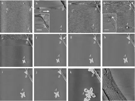
Figure 1 AFM images for crystallization of PEO dendrites and fibers spin-cast from 4×10⁻⁵g·ml−1dilute benzene solution on freshly cleaved mica at 15 °C
The quasi-2D geometry in region B tells a different story. Interestingly, two distinct crystal morphologies, i.e. conventional dendrites and fibrous crystals, are originated from the same single nucleus B at the same time [Fig. 1 (b)]. However, the dendrite in crystal B grows only on the left side of the nucleus, while in crystal A the dendrite grows in four directions. Both dendrites are of the same thickness [(4±1) nm]. The fibrous crystal behaves differently. In Fig. 1 (b), four branches, straight or curved, grow at once in different directions from the nucleus. Meanwhile, fluctuation appears nearby, indicating dramatic diffusion of molecules. During the growing process, new branches, marked by white arrows in Fig. 1 (d, f), emerge from the original nucleation site. And the previous fibers widen in the same period. The latest growing branch, indicated by the arrow in Fig. 1 (f), becomes the widest among all the branches after hours of growing in Fig. 1 (k), while the others keep their shapes and sizes. This demonstrates that the growth of fibrous crystals is diffusion controlled as well, as the supplementary molecules on the right side of the fiber would diffuse and deposit only onto the nearest crystal front. As shown in the phase image of Fig. 1 (l), the wider fiber consists of several parallel aligned lamellae. The average width of a lamella is measured to be (52±3) nm, comparable to the extended, parallel aligned polymer chains [Fig. 2 (b)], since the maximum length of the crystalline PEO in the fully extended state is: L=luN=57-79 nm with lu=0.2783 nm and N is the number of monomer of used PEO [4, 24]. The average thickness of the fibrous crystal is (4±1) nm.
It is difficult to tell the difference between the nucleation sites that give rise to distinct morphologies in Fig. 1. Here, we compare the evolution of the two morphologies in Fig. 2. The formation of conventional dendritic crystal is dominated by the diffusion of polymer coils [Fig. 2 (a)], while the growth of fibrous crystal is from the stretching of polymer chains [Fig. 2 (b)]. In a thin spin-coated film, polymer chains are generally believed to have a distorted chain conformation with reduced inter-chain entanglement [25-28]. And the distorted chains could facilitate the formation of ordered crystalline state due to the lower conformational entropy in the initial stage. The fibrous crystal appears when more orientated chains further deposit onto the preordered crystalline structure. Moreover, the pre-oriented chain conformation in the amorphous region could accelerate the growth rate of the fiber. As shown in Fig. 2 (c), the growth rates of both morphologies could be obtained by following the quickest growing crystal fronts: the lengths of the branches growing fastest are linearly proportional to time. This means that the growth rates are constant with respect to time. Therefore, the growth rate of the fibrous crystal is about 0.5 μm·min−1, while the dendritic one in crystal B grows at the rate of about 0.07 μm·min−1. The growth rate of crystal is usually considered to be thickness dependent according to the results of Sawamura et al. [29]

where G(d) is the growth rate in the thin films of thickness d, G(∞) is the growth rate for infinitely thick films, and a is a constant corresponding to the tube diameter in de Gennes’ reptation model of polymer dynamics. In our case, however, the fiber grows much faster than its dendritic counterpart even though both crystals have about the same thickness. The acceleration in growth rate is attributed to the increase of mobility of the non-equilibrium conformations of the polymer chains, which has been observed in some recent work on spin-cast films [25-28]. Meanwhile, the dendritic crystals have similar behavior to those from the supercooled ultrathin films. In other words, the fibrous crystal may have a smaller constant a value than the dendritic case in the reptation model.
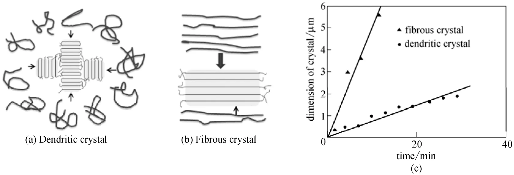
Figure 2 Growth of dendritic (a) and fibrous (b) crystals and their evolution in region B as a function of time on mica at 15 °C (c)

Figure 3 AFM height images for crystallization
We also studied the crystalline PEO ultrathin films in larger area. As illustrated in Fig. 3 (a), the fibrous crystals cover the majority of the substrate and mix with dendrites that could hardly be seen in the image. The crystallization of block copolymer that contains a crystallizable block in the ultrathin films is shown in Fig. 3 (b). Pluronic F127, poly(ethylene oxide)-poly (propylene oxide)-poly(ethylene oxide) (PEO-PPO-PEO), shows similar coexistence of dendritic and fibrous morphologies. The block copolymer crystals are less dense than the pure PEO crystals as expected because of the existence of amorphous block. It is also interesting that the fibrous crystals are more endurable than the dendritic ones. As we know, when crystallization proceeds at a sufficiently high rate, the resulting dendrites tend to be trapped in the non-equilibrium state. Those metastable folded lamellae would relax and reorganize after growth leading to the rearrangement of morphology even well below the melting temperature [6]. Stored at room temperature, the relaxation of dendritic crystals may occur in a period of one week. Meanwhile, the fibrous crystals, marked by the arrow in the bottom insert in Fig. 3 (b), could nicely keep their shapes, indicating the stability of the structure. The large-scale stable fibrous crystals may be useful, for example, for the fabrication of nanofiber-based devices via self-assembly during crystallization. 4 CONCLUSIONS
In a crystallization process of PEO ultrathin film, the formation of two quasi-2D crystal morphologies, i.e. the conventional dendrites and the fibrous crystals, was observed from the original nucleation sites. Both structures grow linearly with time and their growth is dominated by diffusion limited aggregation. Comparing to the dendrites, the fibrous crystals exhibit a faster growth rate due to the shear-induced orientated polymer chains and they are also more stable crystals.
REFERENCES
1 Pearce, R., Vancso, G.J., “Imaging of melting and crystallization of poly(ethylene oxide) in real-time by hot-stage atomic force microscopy”, Macromolecules, 30 (19), 5843-5848 (1997).
2 Pearce, R., Vancso, G.J., “Real-time imaging of melting and crystallization in poly(ethylene oxide) by atomic force microscopy” , Polymer, 39 (5), 1237-1242 (1998).
3 Schultz, J.M., Miles, M.J., “AFM study of morphological development during the melt-crystallization of poly(ethylene oxide)”, J. Polym. Sci. B, 36, 2311-2325 (1998).
4 Reiter, G., Sommer, J.U., “Crystallization of adsorbed polymer monolayers”, Phys. Rev. Lett., 80 (17), 3771-3774 (1998).
5 Reiter, G., Sommer, J.U., “Polymer crystallization in quasi-two dimensions. I. Experimental results”, J. Chem. Phys., 112 (9), 4376-4383 (2000).
6 Reiter, G., Castelein, G., Sommer, J.U., “Liquidlike morphological transformations in mono-lamellar polymer crystals”, Phys. Rev. Lett., 86 (26), 5918-25921 (2001).
7 Zhai, X., Wang, W., Zhang, G., He, B., “Crystal pattern formation and transitions of PEO monolayers on solid substrates from nonequilibrium to near equilibrium”, Macromolecules, 39 (1), 324-329 (2006).
8 Hobbs, J.K., “Insights into polymer crystallization from in-situ atomic force microscopy”, Lect. Notes Phys., 714, 373-389 (2007).
9 Zhang, G., Jin, L., Zheng, P., Shi, A.C., Wang, W., “Labyrinthine pattern of polymer crystals from supercooled ultrathin films”, Polymer, 51, 554-562 (2010).
10 Zhang, G., Cao, Y., Jin, L., Zheng, P., van Horn, R. M., Lotz, B., Cheng, S.Z.D., Wang, W., “Crystal growth pattern changes in low molecular weight poly(ethylene oxide) ultra thin films”, Polymer, 52, 1133-1140 (2011).
11 Shen, B., Liang, Y., Zhang, C., Hang, C.C., “Shear-induced crystallization at polymer-substrate interface: the slippage hypothesis”, Macromolecules, 44 (17), 6919-6927 (2011).
12 Han, X., Hu, J., Liu, H., Hu, Y., “SEBS aggregate patterning at a surface studied by atomic force microscopy”, Langmuir, 22, 3428-3433 (2006).
13 He, G.L., Messina, R., Lowen, H., Kiriy, A., Bocharova, V., Stamm, M., “Shear-induced stretching of adsorbed polymer chains”, Soft Matter, 5, 3014-3017 (2009).
14 Li, L., Chan, C.M., Li, J.X., Ng, K.M., Yeung, K.L., Weng, L.T., “A direct observation of the formation of nuclei and the development of lamellae in polymer spherulites”, Macromolecules, 32, 8240-8242 (1999).
15 Baert, J., van Puyvelde, P., “Density fluctuations during the early stages of polymer crystallization: An overview”, Macrom. Mater. Eng., 293, 255-273 (2008).
16 Chuang, W.T., Su, W.B., Jeng, U.S., “Formation of mesomorphic domains and subsequent structural evolution during cold crystallization of poly(trimethylene terephthalate)”, Macromolecules, 44, 1140-1148 (2011).
17 Russo, J., Tanaka, H., “Selection mechanism of polymorphs in the crystal nucleation of the Gaussian core model”, Soft Matter, 8,4206-4215 (2012).
18 Borodin, O., Smith, G.D., Bandyopadhyaha, R., Byutner, O., “Molecular dynamics study of the influence of solid interfaces on poly(ethylene oxide) structure and dynamics”, Macromolecules, 36, 7873-7883 (2003).
19 Vogel, M., “Rotational and conformational dynamics of a model polymer melt at solid interfaces”, Macromolecules, 42, 9498-9505 (2009).
20 Wang, Y., Sun, J., Li, L., “What is the role of the interfacial interaction in the slow relaxation of nanometer-thick polymer melts on a solid surface?”, Langmuir, 28 (14), 6151-6156 (2012).
21 Despotopoulou, M.M., Frank, C.W., Miller, R.D., “Kinetics of chain organization in ultrathin poly(di-n-hexylsilane) films”, Macromolecules, 29, 5797-5804 (1996).
22 Witten, T.A., Sander J, L.M., “Diffusion-limited aggregation, a kinetic critical phenomenon”, Phys. Rev. Lett., 47, 1400-1403 (1981)
23 Ball, R., Nauenberg, M., Witten, T.A., “Diffusion-controlled aggregation in the continuum approximation”, Phys. Rev. A, 29, 2017 (1984).
24 Kovacs, A.J., Gonthier, A., Kolloid, Z.Z., “Crystallization and fusion of self-seeded polymer: II. Growth rate, morphology and isothermal thickening of single crystals of low molecular weight poly(ethyleneoxide) fractions”, Polymer, 250 (5), 530-551(1972).
25 Raegen, A., Chowdhury, M., Calers, C., Schmatulla, A., Steiner, U., Reiter, G., “Aging of thin polymer films cast from a near-theta solvent”, Phys. Rev. Lett., 105, 227801 (2010)
26 Reiter, G., de Gennes, P., “Spin-cast, thin, glassy polymer films: Highly metastable forms of matter”, Eur. Phys. J. E, 6, 25-28 (2001)
27 Barbero, D.B., Steiner, U., “Nonequilibrium polymer rheology in spin-cast films”, Phys. Rev. Lett., 102, 248303 (2009)
28 Thomas, K.R., Chenneviere, A., Reiter, G., Steiner, U., “Nonequilibrium behavior of thin polymer films”, Phys. Rev. E, 83, 021804 (2011)
29 Sawamura, S., Miyaji, H., Izumi, K., Sutton, S.J., Miyamoto, Y.,“Growth rate of isotactic polystyrene crystals in thin films”, J. Phys. Jpn., 67 (10), 3338-3341(1998).
APPENDIX
A1 Crystallization in PEO ultrathin films
A1.1 Films casting from 4×10⁻⁵g·ml−1solution
The crystallization processes of fibrous and dendritic crystals have been observed on various samples. The growths of separate fibers and dendrites were followed by AFM on samples spin-cast from a 4×10⁻⁵g·ml−1dilute benzene solution on freshly cleaved mica at 15 °C.
A1.2 Films casting from 4×10⁻⁴g·ml−1solution
Samples cast from more concentrated solutions see similar morphologies as well, though they are always accompanied by‘knot’ structures due to the thicker initial films. PEO crystal morphologies on samples spin-cast from a 4×10⁻⁴g·ml−1dilute benzene solution on freshly cleaved mica at 15 °C were shown below.
A2 Crystallization in F127 ultrathin films
A2.1 Films casting from 4×10⁻⁵g·ml−1solution
The crystallization of triblock copolymer F127 (PEO-PPO-PEO) was also investigated, which showed the similar coexistence of the dendritic and fibrous morphologies. As shown below, F127 crystal morphologies were obtained from samples spin-cast from a 4×10⁻⁵g·ml−1dilute benzene solution on freshly cleaved mica at 15 °C.
A2.2 Films casting from 4×10⁻⁴g·ml−1solution
Unlike the pure PEO thicker films with knot structures, samples spin-cast from a 4×10⁻⁴g·ml−1F127 dilute benzene solution exhibited similar morphologies to that from thinner films (i.e. from 4×10⁻⁵g·ml−1solution) because of the less crystalline of the block copolymer.

Figure A1 A sequence of in-situ AFM height images (20 μm×20 μm) of PEO fibrous crystal taken at (a) t=0 min; (b) t=8 min; (c) t=40 min, the arrow indicates the beginning of a side branch; and (d) t=83 min. The thickness of the crystal is (4±1) nm

Figure A2 A sequence of in-situ AFM height images (20 μm×20 μm) of PEO dendritic crystal taken at (a) t=0 min, (b) t=3 min, (c) t=6 min, and (d) t=91 min (the scale bar is 1 μm). The arrows indicate the depletion of an amorphous droplet. The thickness of the dendritic crystal is about 3-5 nm
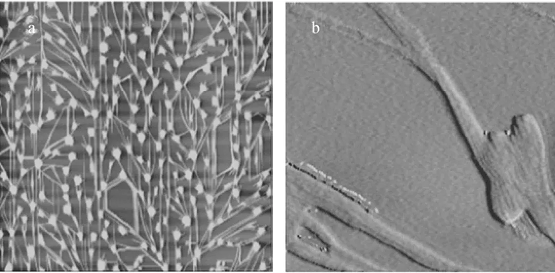
Figure A3 (a) AFM height images of PEO fibrous crystal (20 μm×20 μm). (b) Phase image of the fibrous crystals connected by knot consists of parallel aligned crystal lamellae (1μm×1 μm). The thickness of the fibers is about 5 nm and that of the knot is about 10 nm
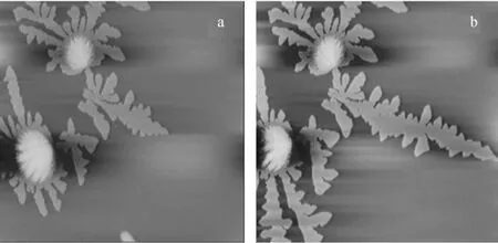
Figure A4 In-situ AFM height images (20μm×20 μm) of PEO dendritic crystal taken at (a) t=0 min, and (b) t=4 min. Like the fibrous crystals (Fig. A3), the dendrites consist of knot crystals as well. The thickness of the crystal is about 3 nm and that of the knot is about 15 nm
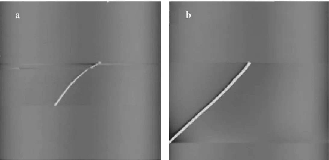
Figure A5 In-situ AFM height images (20 μm×20 μm) of F127 fibrous crystal taken at (a) t=0 min, and (b) t=4 min. The thickness of the dendrite is from 3-4 nm (a) to about 9 nm (b)
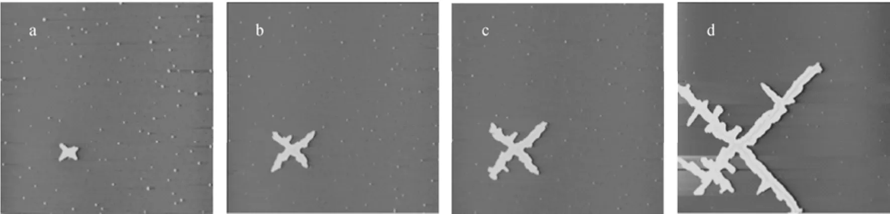
Figure A6 A sequence of in-situ AFM height images (20μm×20 μm) of F127 dendritic crystal taken at (a) t=0 min, (b) t=3 min, (c) t=7 min, and (d) t=34 min. The thickness of the dendrite is from 6 nm (a) to 7 nm (d). The edge of the crystal is a bit thicker than the interior (around 12 nm) (d)
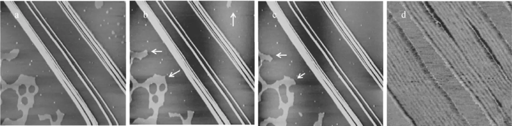
Figure A7 A sequence of in-situ AFM height images (20 μm×20 μm) of F127 fibrous crystal taken at (a) t=0 min, (b) t=62 min, and (c) t=150 min. The arrows indicate the depletion of the amorphous zones. The thicknesses of the crystal and amorphous zones are about 4 and 1 nm, respectively. (d) Phase image of the fibrous crystals consist of parallel aligned crystal lamellae (1μm×1 μm). The average width of a lamella is (26±2) nm corresponding to the extended PEO chains. The theoretical calculation of the maximum length of the crystalline PEO block in the fully extended state is: L=luN=28 nm (lu=0.2783 nm and N is the number of monomer of PEO block)
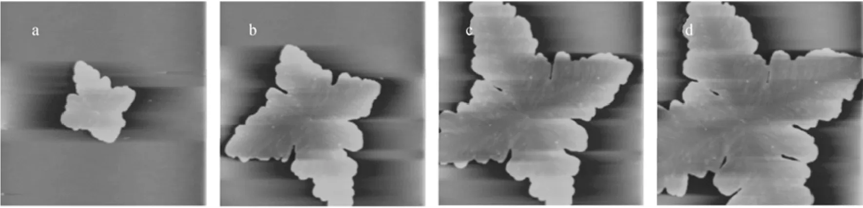
Figure A8 A sequence of in-situ AFM height images (20 μm×20 μm) of F127 dendritic crystal taken at (a) t=0 min, (b) t=4 min, (c) t=9 min, and (d) t=13 min. The thickness of the dendrite is (4.5±1) nm
CHEMICAL ENGINEERING THERMODYNAMICS
Chinese Journal of Chemical Engineering, 22(3) 339—345 (2014)
10.1016/S1004-9541(14)60046-X
2012-11-18, accepted 2013-03-18.
*Supported by the National Natural Science Foundation of China (21176065, 21136004), the 111 Project (B08021) and the Fundamental Research Funds for the central Universities of China.
**To whom correspondence should be addressed. E-mail: xhan@ecust.edu.cn
 Chinese Journal of Chemical Engineering2014年3期
- Chinese Journal of Chemical Engineering的其它文章
- A Bi-component Cu Catalyst for the Direct Synthesis of Methylchlorosilane from Silicon and Methyl Chloride
- Hydrodynamics and Mass Transfer of Oily Micro-emulsions in An External Loop Airlift Reactor
- Effects of Shape and Quantity of Helical Baffle on the Shell-side Heat Transfer and Flow Performance of Heat Exchangers*
- A Contraction-expansion Helical Mixer in the Laminar Regime*
- Preparation and Characterization of Sodium Sulfate/Silica Composite as a Shape-stabilized Phase Change Material by Sol-gel Method*
- Determination of Transport Properties of Dilute Binary Mixtures Containing Carbon Dioxide through Isotropic Pair Potential Energies