
Calibration method for electrode gains in an axially symmetric stripline BPM∗
2014-08-05 09:13WUFangFang吴芳芳ZHOUZeRan周泽然YANGYongLiang杨永良SUNBaoGen孙葆根ZOUJunYin邹俊颖LUPing卢平CHENGChaoCai程超才LUOQing罗箐andXUJun徐君
Nuclear Science and Techniques 2014年5期
WU Fang-Fang(吴芳芳),ZHOU Ze-Ran(周泽然),YANG Yong-Liang(杨永良),SUN Bao-Gen(孙葆根),,ZOU Jun-Yin(邹俊颖),LU Ping(卢平),CHENG Chao-Cai(程超才),LUO Qing(罗箐),and XU Jun(徐君)
1National Synchrotron Radiation Laboratory&School of Nuclear Science and Technology, University of Science and Technology of China,Hefei 230029,China
Calibration method for electrode gains in an axially symmetric stripline BPM∗
WU Fang-Fang(吴芳芳),1ZHOU Ze-Ran(周泽然),1YANG Yong-Liang(杨永良),1SUN Bao-Gen(孙葆根),1,†ZOU Jun-Yin(邹俊颖),1LU Ping(卢平),1CHENG Chao-Cai(程超才),1LUO Qing(罗箐),1and XU Jun(徐君)1
1National Synchrotron Radiation Laboratory&School of Nuclear Science and Technology, University of Science and Technology of China,Hefei 230029,China
The four electrodes in the stripline beam position monitor(BPM)for Hefei Light Source(HLS II)storage ring are of axially symmetric type.We have derived a new calibration method of electrode gains for this type stripline BPM.The gain fi t error of different data grids was analyzed,and the±5mm by±5mm grid is the best. The electrode gains of two stripline BPMs(HLS II SR-BD-STLB1 and HLS II SR-BD-STLB2)were obtained based on of fl ine calibrated data.The results show that data after fi tting gains are improved,with the electrode gains being between 0.94 and 1.15.
Stripline beam position monitor,Electrode gain,Axially symmetric,Calibration
I.INTRODUCTION
The Hefei Light Source(HLS)is being upgraded to HLS II.Three stripline BPMs are designed to measure the beam position,emittance and momentum dispersion in the storage ring.To decrease beam emittance,the circular vacuum chamberofthestorageringwillbechangedtoanoctagonaltype.A cross-sectionofthestriplineBPMisshowninFig.1(inmm). Due to mechanical errors of the stripline BPM,the four axially symmetric electrodes,labeled with#R,#L,#T and#B to denote the horizontal(left and right)and vertical(top and bottom)electrodes,do not have the same relative gain.The differences in electrode gain will couple the measured horizontal position with the vertical position,resulting in measurement errors[1].To measure beam parameters correctly, the electrode gains of a stripline BPM shall be measured.
Electrode gain for button BPM was measured by Rubinet al.[1].This method requires mirror symmetry geometry of the four BPM electrodes.Geometry of the four BPM electrodes can be mirroring symmetric or axially symmetric.The measurement method of electrode gains for stripline BPM of the mirroring symmetric type is the same as the method for buttonBPMs.ThegeometryofBPMelectrodesontheHLSII storage ring is axially symmetric,and an of fl ine measurement method is developed to measure the electrode gains,which uses three electrode gains and a correction factor.
II.METHODS
The quadrupole component with difference/sum method for the stripline BPM can be expressed as Eq.(1):
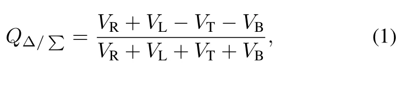
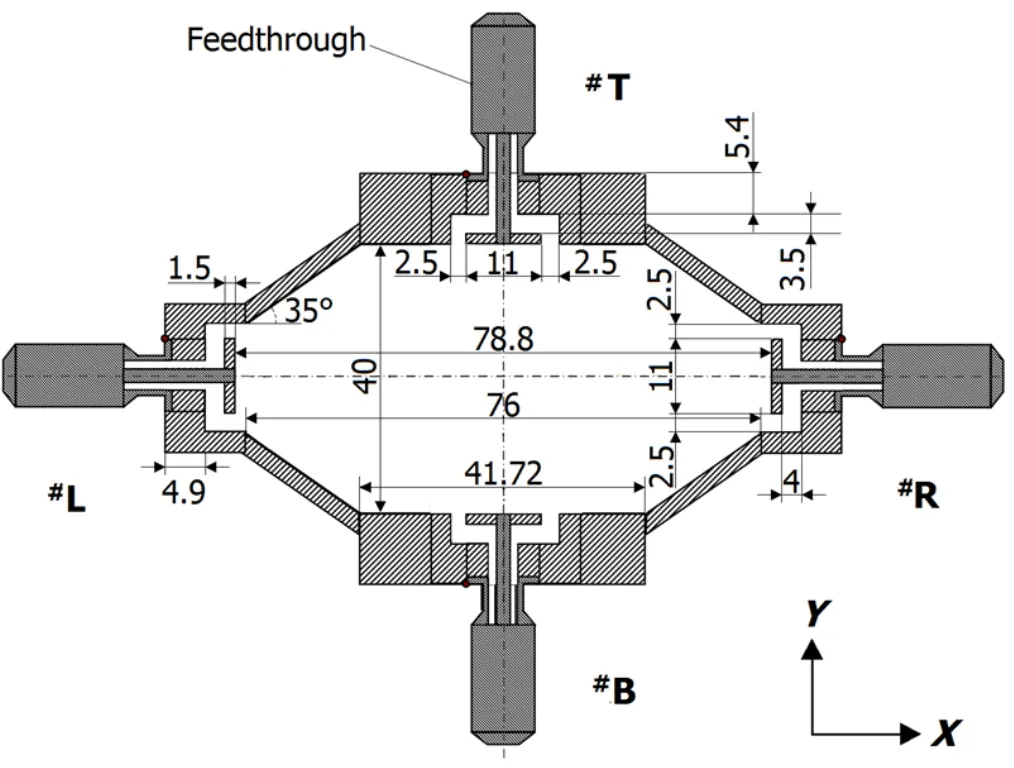
Fig.1.The cross-section of the stripline BPM for the HLS II storage ring.
whereVR,VL,VTandVBare electrode signals for the four electrodes.Assuming that the#R,#L,#T and#B electrodes are inXandYaxis,as shown in Fig.1,and ignoring the higher order components,the quadrupole component for stripline BPM of axially symmetric type for circular vacuum chamber[2,3]can be calculated by Eq.(2):
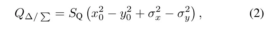
where(x0,y0)is the beam position in the BPM,(σx,σy)is thebeamtransversesize,andSQisthequadrupolecomponent sensitivity,which is relevant to azimuthal opening angle of the electrodes and distance from electrode to the BPM center.
For a stripline BPM of the axially symmetric type on an octagonalvacuum chamber,the boundaryelementmethod[4] and gaussian weighted method of 2D-grid structure[5]are used to simulate beam moving in the BPM.The model for stripline BPMs in the HLS II storage ring was established based on the boundary element method using Matlab.
The quadrupole componentQΔ/∑for the stripline BPM
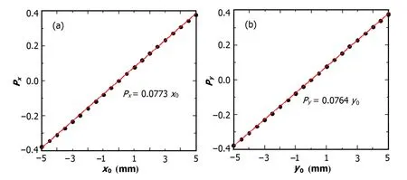
Fig.2.(Color online)Horizontal(a)and vertical(b)sensitivities using the difference/sum method.
on the HLS II storage ring can be calculated as:

As the distance between horizontal electrodes differs from that between vertical electrodes,there exists a non-zero componentQ0,compared to the stripline BPM on a circular vacuum chamber.
Ignoring the higher order components,the electrical position(Px,Py)can be obtained using the difference/sum method:
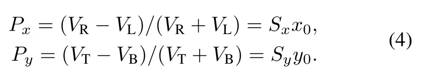
Combining Eqs.(3)and(4)to eliminatex0andy0,we can obtain an expression that relates the electrode signals and beam transverse size:

By using point charge to substitute gaussian beam,(σx,σy) becomes(0,0),and Eq.(5)changes to:
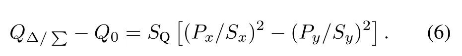
HLS is being upgraded,so the electrode gains can be measured of fl ine,rather than online.Two stripline BPMs(HLS II SR-BD-STLB1 and HLS II SR-BD-STLB2)were calibrated[6]by using antenna method,with an antenna of 0.2-mm tungsten filament.This situation can be regarded as that the beam passes the stripline BPM with(σx,σy)being (0.2mm,0.2mm)and=0,so the electrode gains can be calculated using Eq.(6).
Before measuring the electrode gains,the parameters(Sx,Sy,Q0,SQ)shall be calculated.The boundary element method[4]was used to simulate a point charge moving in a grid of±5mm by±5mm with a 0.5 mm step.The four electrode signals ofVR,VL,VTandVBwere obtained to calculate the beam positions(Fig.2)using Eq.(4).The position sensitivities(SxandSy)can be obtained by fitting the simulation data.As shown in Fig.2,Sx=0.0773mm andSy=0.0764mm.The quadrupole componentcalculated using Eq.(1)at the point charge position(x0,y0) from(0,0)to(5,5)only,due to symmetry,is shown in Fig.3.By plotting and fitting the data ofat(x,y)from(−5,
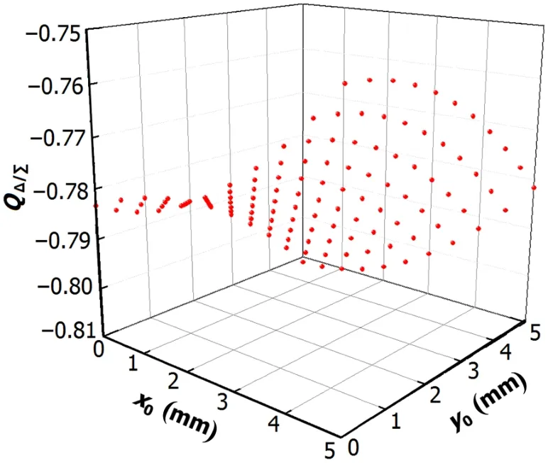
Fig.3.(Color online)Simulatedas functions ofx0andy0.
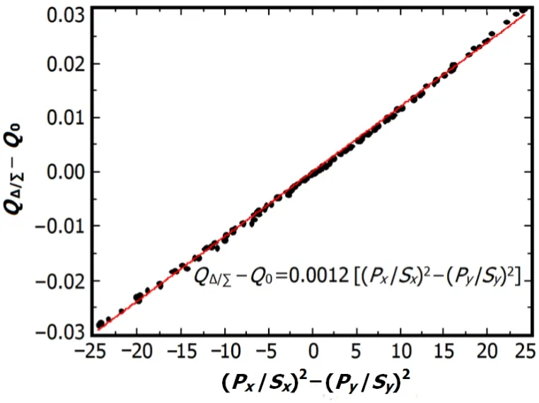
Fig.4.(Color online)Simulation and fitting ofvs.
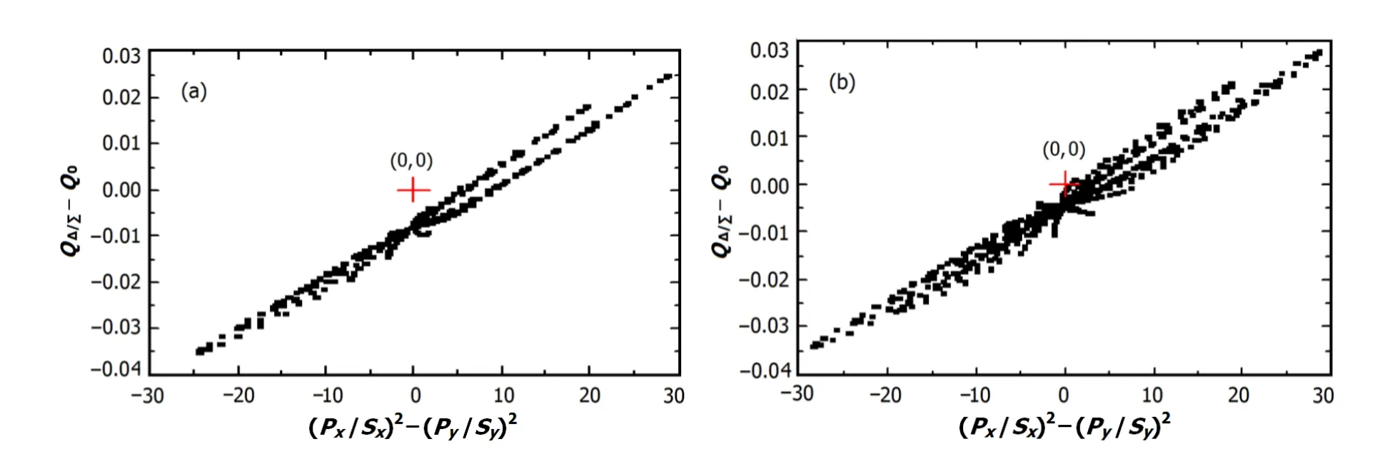
Fig.5.(Color online)(a)simulated with 8%signal reduction of electrode#R,(b)calibrated on HLS II SR-BD-STLB1.
−5)to(5,5),the parameters ofQ0andSQcan be obtained using Eq.(6).Since electrode gains would be of fl ine measured based on Eq.(6),in order to directly obtain constraints on the four electrode signals and decrease calculation error,should be replaced byAs shown in Fig.4,(0)varies linearly with,andQ0=−0.7832 andSQ=
0.0012 mm−2by the fitting data.
III.GAIN ERROR OF THE BPM ELECTRODES
In practice,due to mechanical errors of stripline BPM,the four electrodes do not have the same gain,hence the failure of the connection between electrodes defined by Eq.(6).The effect of gain errors was simulated by an 8%reduction of the signal on electrode#R.Fig.5(a)showsvsunder this condition for±5mm by±5mm grid simulated data.The relationship betweenandisnolongerlinear, deviating from zero(marked by the+sign).The BPM(HLS II SR-BD-STLB1)was calibrated of fl ine[6].The results are shown in Fig.5(b).The situation is similar to Fig.5(a). Therefore,the four electrodes of this BPM have different gains.
Due to the gain error of the four electrodes of the BPM, Eq.(6)cannot be applicable.So,a nonlinear least square fitting method was used to get the electrode gains(gR,gL,gTandgB).The merit function is
wherecis a coef fi cient to correctSQ.
The best fit gains(gR,gL,gTandgB)andcare obtained at a minimizedχ2.The method was used by Rubinet al.[1],and they got their desirable results by controlling the gain equals to 1 every time for each of the#R,#L,#T and#B electrodes,and averaging the data from the fitting measurement. They found also that different grid data affected the gain fit algorithm.So,gainfiterrorwasanalyzedwithdifferentgrids. Fig.6 shows that gain fit error for three different grids,with 1%–12%reduction of the electrode signal.For each fit,the relative difference of the fitted gains from the real gains was calculatedbyΔg=(|gfitted−greal|/greal)×100%.FromFig.6, the difference in data grid size affected the gain fit algorithm. The±3mm by±3mm grid is too small in size,hence the biggest gain fit errors,while the±8mm by±8mm grid is too big to ignore the higher order components and to justify Eqs.(3)and(4),which can be satisfied only in certain range of the stripline BPM.We found that of all the data grids,the±5mm by±5mm grid has the least gain fit error,so it was chosen to measure electrode gains.
IV.RESULTS OF CALIBRATION
Two BPMs,HLS II SR-BD-STLB1 and HLS II SR-BDSTLB2,were calibrated of fl ine[6].The beam was simulated by using 0.2 mm tungsten filament.The filament relative to the BPM was moved by stepper motor in a±5mm by±5mm grid,the data was acquired by Libera Brilliance[7].The fitting results for HLS II SR-BD-STLB1 are given in Fig.7, which shows that the data points after gain fitting are linear and pass through zero(0,0).Fitted gains for the two BPMs are shown in Fig.8,where the electrode gains are between 0.94 and 1.15.

Fig.7.(Color online)(QΔ/∑−Q0)vs.[(Px/Sx)2−(Py/Sy)2]for of fl ine raw data and data after gain fitting of HLS II SR-BDSTLB1.
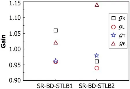
Fig.8.(Color online)Fitted gains from of fl ine calibrated data for the BPMs of HLS II SR-BD-STLB1 and HLS II SR-BD-STLB2.
V.CONCLUSION
We have derived of fl ine measurement method of electrode gains for axially symmetric type stripline BPM.The simulation results show that fitted electrode gain error is the least in a±5mm by±5mm grid,(QΔ/∑−Q0)vs ?(Px/Sx)2−(Py/Sy)2?curve after gain fitting is linear and passes through zero.In the future,online measurement of the electrode gains will be performed and the results be compared with the of fl ine results.
ACKNOWLEDGEMENTS
The authors wish to thank the HLS beam measurement group for discussion and suggestion.
[1]Rubin D L,Billing M,Meller R,et al.Phys Rev Spec Top-AC, 2010,13:092802.
[2]Miller R H,Clendenin J E,James M B,et al.Nonintercepting Emittance Monitor,SLAC-PUB-3186,1983.
[3]Fang J,Sun B G,Lu P,et al.Atom Energ Sci Technol,2011,44: 511–516.(in Chinese)
[4]Olmos A,P´erez F,Rehm G.Matlab Code for BPM Button Geometry Computation.Proceedings of DIPAC 2007,186–188. Venice,Itally,2007.
[5]Russell J S,Gilpatrick D J,Power J F,et al.Characterization of beam position monitor for measurement of second moment. Proceedings of PAC 1995,2580–2582.Dallas,USA,1995
[6]Wu F F,Zhou Z R,Sun B G,et al.High Power Laser Part Beam, 2011,23:2971–2975.(in Chinese)
[7]Ma T J,Yang Y L,Sun B G,et al.Nucl Sci Tech,2012,23: 261–266.
10.13538/j.1001-8042/nst.25.050102
(Received March 4,2014;accepted in revised form May 1,2014;published online October 6,2014)
∗Supported by the Natural Science Foundation of China(Nos.11175173, 11375178 and 11005105)
†Corresponding author,bgsun@ustc.edu.cn
 Nuclear Science and Techniques2014年5期
- Nuclear Science and Techniques的其它文章
- Dose rate distribution of photoneutrons in an ID beamline of SSRF:simulations and measurements
- A study of quasi-absolute method in photon activation analysis∗
- High-resolution boosted reconstruction of γ-ray spectra∗
- A fractionation model based on three lognormal particle size distributions
- Model-predictive control of power supply for particle accelerators∗
- Biological characteristics of[18F]-THK523 for tau imaging∗