
Interval Fault Tree Analysis of Excavator Variable-Frequency Speed Control System
2014-08-12 02:31WANGXiaoming王晓明LIAifeng李爱峰ZHANGYongming张永明MIJinhua米金华HUANGHongzhong黄洪钟
WANG Xiao-ming (王晓明), LI Ai-feng (李爱峰), ZHANG Yong-ming (张永明), MI Jin-hua (米金华), HUANG Hong-zhong (黄洪钟)
1 Taiyuan Heavy Industry Co., Ltd., Taiyuan 030024, China 2 School of Mechanical Electronic and Industrial Engineering, University of Electronic Science and Technology of China, Chengdu 611731, China
Interval Fault Tree Analysis of Excavator Variable-Frequency Speed Control System
WANG Xiao-ming (王晓明)1*, LI Ai-feng (李爱峰)1, ZHANG Yong-ming (张永明)1, MI Jin-hua (米金华)2, HUANG Hong-zhong (黄洪钟)2
1TaiyuanHeavyIndustryCo.,Ltd.,Taiyuan030024,China2SchoolofMechanicalElectronicandIndustrialEngineering,UniversityofElectronicScienceandTechnologyofChina,Chengdu611731,China
In consideration of the uncertainty of basic events failure rate and lack of probability statistical information in fault tree analysis (FTA) of excavator variable-frequency speed control system, the interval theory was employed and combined with conventional FTA method. The basic events failure probabilities were described by interval numbers, and the interval operators of logical gates in FTA were deduced based on interval theory. Finally, the reliability assessment of excavator variable-frequency speed control system was done by interval FTA method. The result shows that the interval FTA method is suitable for the complex system with insufficient failure data.
faulttreeanalysis(FTA);intervaltheory;intervalprobability;excavator;electricalsytem
Introduction
The large mining excavator is produced as mining equipment for large open pit mine. After nearly five decades of development, the main bucket capacity of products is from 10 m3to 75 m3. It has turned into the main mining equipment of the million-ton large-scale open mines. As the main core control system of excavator, the reliability of electric system and its subsystem like variable-frequency speed control system, directly affect the efficiency of the whole excavator[1-2].
Fault tree analysis (FTA) method is a systematic deductive and graphical method, and widely used in reliability analysis and assessment for complex system.The uncertainty of whole system failure can be measured by probability theory; therefore, the traditional fault tree analysis method based on probability has been proved to be very useful and commonly used in system engineering as a system analysis method[3-7].
Due to lack of information and sufficient data, especially when the failure probability of a large complex system is estimated, considering the uncertainty of estimated value, the failure probability is always treated as a random variable subject to a known distribution. There are various research works on the reliability problem with uncertain input data, for instance, fuzzy fault tree analysis method based on fuzzy theory[3-4], and interval fault tree analysis method based on Dempster-Shafer (D-S) evidential theory[5-7].
In this paper, considering the uncertainty of bottom events of fault tree, the occurrence probabilities of bottom events are expressed as interval numbers. The interval theory are employed and combined with conventional FTA method to analyze the reliability of excavator variable-frequency speed control system. The remainder of this paper is organized as follows: the excavator variable-frequency speed control system is briefly introduced in Section 1. The fault tree model is constructed by conventional FTA method. Section 2 reviews the interval theory and proposes interval operator of logical gates in FTA. The detail reliability analysis of variable-frequency speed control system is also presented in this section. Section 3 concludes this paper.
1 Fault Tree Modeling of Excavator Variable-Frequency Speed Control System
1.1 Variable-frequency speed control system
The operating mechanism of large mining excavator can be divided into five parts based on its different functions,i.e., lifting mechanism, travelling mechanism, crowding mechanism, swing mechanism, and bucket open mechanism. The variable frequency and speed regulation electric system is used to control and coordinate the actions of operating mechanisms. The working principle of a kind of common used variable-frequency speed control systems is shown in Fig.1.
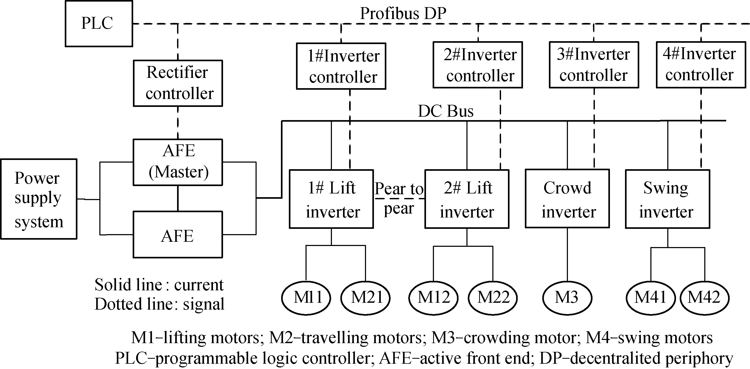
Fig.1 Working principle of variable-frequency speed control system of WK series large excavators
In order to regulate the speed smoothly, the direct current (DC) power with stable voltage is transferred into an alternating current (AC) power with adjustable voltage and frequency by the inverter mounted on a common DC bus. Lifting mechanism is driven by two rigidly-connected motors with consistent speed, and driven by two inverters respectively. A master-slave torque controlling method is applied to realizing the output equilibrium of two lifting motors. The crowding mechanism is driven by a single AC variable-frequency motor which is controlled by an inverter cabinet, and swing mechanism has two geared variable-frequency motors driven by one inverter. Especially, the two motors of travelling mechanism are also driven by two independent inverters which are shared with lifting mechanism, and working patterns switch between lifting and travelling are performed by an AC contactor in switching cabinet, which is clearly shown in Fig.1.
1.2 Fault tree construction
On the basis of previous work in the failure mode and effects analysis (FMEA) results of the entire electrical system, the “operating mechanism variable-frequency speed control system failure” is chosen as the top event. According to the rules of building fault trees, the failure models of whole system are composed of those four mainly failures, including motors damage, inverters failure, encoder doesn’t work and brake. Then taking the components and parts failure models as the bottom events, the fault tree of variable-frequency speed control system is built and shown in Fig.2.
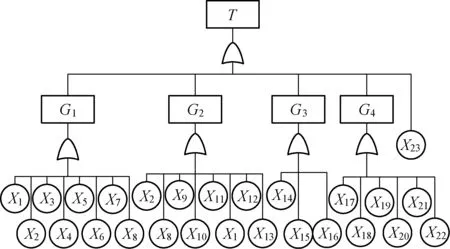
Fig.2 The fault tree of variable-frequency speed control system
The meanings of the notations in Fig.2 are as follows:T: operating mechanism variable-frequency speed control system failure;G1: lifting mechanism failure;G2: travelling mechanism failure;G3: crowding mechanism failure;G4: swing mechanism failure;X1: front lifting inverter 1 failure;X2: front lifting motorM11failure;X3: encoder 1 of front lifting motor failure;X4: lifting brake;X5: back lifting inverter 2 failure;X6: back lifting motorM12failure;X7: encoder 2 of back lifting motor failure;X8: switch cabinet failure;X9: left travelling motorM21failure;X10: encoder 3 of left travelling motor failure;X11: travelling brake;X12: right travelling motorM22failure;X13: encoder 4 of right travelling motor failure;X14: crowd inverter 3 failure;X15: crowding motorM3failure;X16: encoder 5 of crowding motor failure;X17: swing inverter failure;X18: front-left swing motorM41failure;X19: encoder 6 of swing motor failure;X20: front-right swing motorM42failure;X21: back swing motor failureM43failure;X22: swing reactor failure;X23: bucket opening motor failure. In the following parts, usexi(i=1, 2, …, 23) to represent the random variables of eventsXi.
Because of the insufficient of data, the precise probabilities of bottom events cannot be obtained, so the conventional quantitative analysis method is out of use. In this paper, by looking up the handbook of mechanical design [8], as well as integrating the knowledge of various relevant experts, the failure probabilities of bottom events are determined by using the following method. Iftis set to 200 h and taking 10 percent of the deviation of the expected value as the upper and lower bounds, the interval failure probabilities of bottom events are tabulated in Table 1.
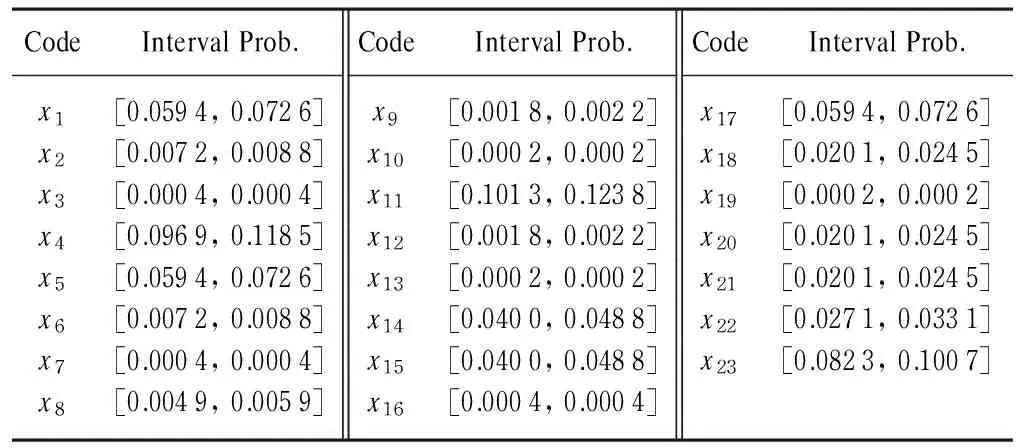
Table 1 Bottom events and interval failure probability
Note: Prob. means probability
2 Reliability Analysis of Excavator Variable-Frequency Speed Control System
2.1 The structure function of fault tree
Assume that the system and its components are all binary, and the faults between various components are independent. For the fault tree of variable-frequency speed control system, it hasn=23 bottom events and the top event isT. According to the basic definition of fault tree, the state variable of top eventΦcan be expressed as a function of state variables of bottom eventsxi(i= 1, 2, …,n), that is:
(1)

2.2 FTA based on interval theory

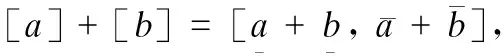
(1) Interval operator of AND gate
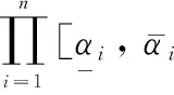
(2)
(2) Interval operator of OR gate

(3)

(4)
(5)
The output probability of AND and OR gates withnbottom events can be calculated, accordingly, using the interval method to analyze the fault tree and the failure probability of top events can be calculated.
The importance of the components in system not only depends on its physical structure but its reliability. The importance of interval probability of the top event can be defined as:
(6)
where [F]iis the interval probability of basic eventxi, and [g(F)] is the interval failure probability function of the top event.
2.3 Qualitative and quantitative analyses of fault tree
In order to find the cut set of a fault tree, which is the smallest combination of basic events that directly lead to system failure, the Fussell-Vesely method and Semanderes method are the most common used methods for seeking fault tree minimal cut sets[9]. In this paper, the Semanderes method which is based on the sets operation rules, is chosen to find minimal cut sets of the fault tree of variable-frequency speed control system.
The bottom level of fault tree is given by:
G1=x1∪x2∪x3∪x4∪x5∪x6∪x7∪x8,
G2=x1∪x2∪x8∪x9∪x10∪x11∪x12∪x13,
G3=x14∪x15∪x16,
G4=x17∪x18∪x19∪x20∪x21∪x22.
And the top level is expressed as:
M4=G1∪G2∪G3∪G4∪x23=
(x1∪x2∪x3∪x4∪x5∪x6∪x7∪x8)∪
(x1∪x2∪x8∪x9∪x10∪x11∪x12∪x13)∪
(x14∪x15∪x16)∪x23∪
(x17∪x18∪x19∪x20∪x21∪x22)=
x1∪x2∪…∪x23
(7)
There are 23 product terms in Eq. (7), and we finally find 23 minimal cut sets of variable-frequency speed control system: {x1}, {x2}, …, {x23}.
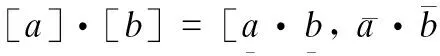
The interval probability of basic event is [F]xi, according to Eq.(3) the definition of interval operator of OR gate and the qualitative analysis of fault tree, the failure probability of middle events and top event are given by:

And the minimal cut sets are independent, the failure probability of top event is:
(8)
According to the parameters listed in Table 1, the following failure probability of top event att=200 h can be obtained:
[F]T=[0.4899, 0.5633].
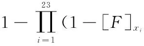
The fauilre rate of variable-frequency speed control system isλs=[3366, 4143]×10-6. Since the interval probability of top event cannot directly reflect in the distribution of the failure rate. The sampling simulation method is used to do random simulation on interval failure probabilities of basic events. After 1 000 times of independent sampling and simulation, the failure rate distribution of top event on fault interval is shown in Fig.3. It is obviously that the simulation result is consistent with the theoretical result.
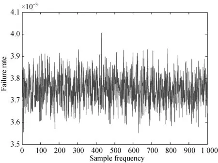
Fig.3 The failure rate distribution on fault interval
According to Eq. (6) and the algorithm of the interval number, the probability importance of the bottom event can be computed by the proposed method, and the results are listed in Table 2.
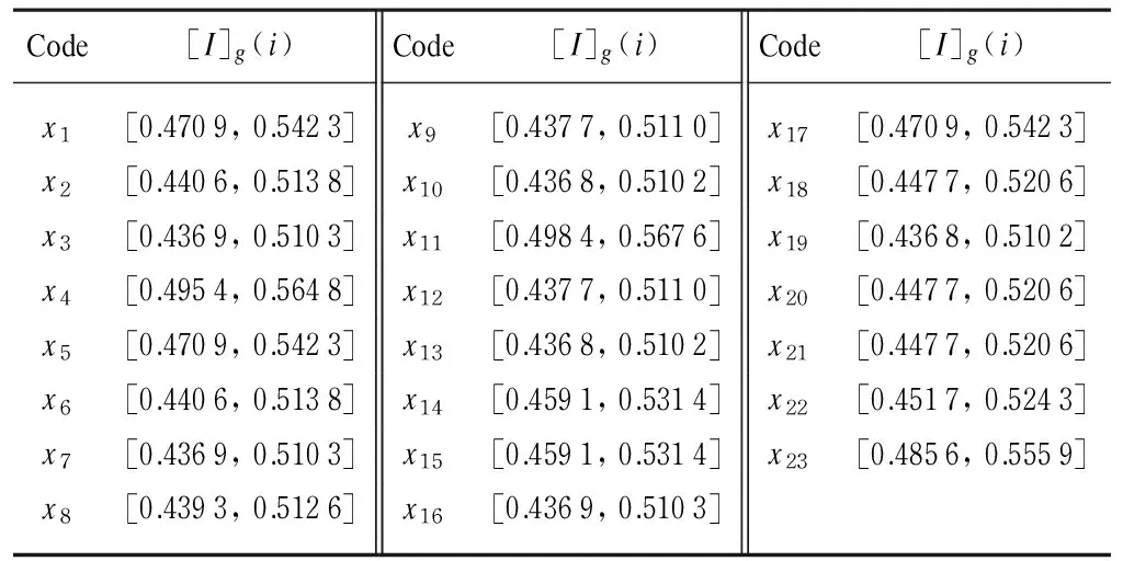
Table 2 The probability importance factor of bottom events

Ig(11) ≥Ig(4)≥Ig(23)≥Ig(17)≥Ig(1)≥Ig(5)≥Ig(14)≥Ig(15)≥Ig(22)≥Ig(18)≥Ig(20)≥Ig(21)≥
Ig(2)≥Ig(6)≥Ig(8)≥Ig(12)≥Ig(9)≥Ig(3)≥
Ig(7)≥Ig(16)≥Ig(13)≥Ig(10)≥Ig(19).
3 Conclusions
Because of the lack of information and insufficient failure data of the basic events are available, the uncertainty is introduced in the FTA of complex system. In this paper, the interval theory is employed and combined with conventional FTA method, using interval number rather than a precise value to represent the occurrence probabilities of bottom events. The interval operators of logical gates of FTA are deduced. The interval FTA method is used to estimate the reliability of excavator variable-frequency speed system. The NSG ranking method is used to sort the interval importance of basic events, and this result is able to provide a reasonable guidance for fault diagnosis and maintenance of excavator variable-frequency speed system. The study in this paper shows that the interval FTA method is suitable for the reliability analysis of complex system with insufficient failure data.
[1] Miao G C, Liu X X. Electric Failure Types and Self-diagnosis System of WK-35 Power Shovel[J].MechanicalEngineering&Automation, 2010, 163(6): 125-127. (in Chinese)
[2] Miao G C. The Variable-Frequency Speed Control Electrical System of WK Series Large Excavator[J].OpencastMiningTechnology, 2012(4): 34-38.(in Chinese)
[3] Li Y F, Huang H Z, Liu Y,etal. A New Fault Tree Analysis Method: Fuzzy Dynamic Fault Tree Analysis[J].EksploatacjaiNiezawodnosc-MaintenanceandReliability, 2012, 14(3): 208-214.
[4] Mi J H, Li Y F, Li H Q,etal. Reliability Analysis of CNC Hydraulic System Based on Fuzzy Fault Tree[C]. 2011 International Conference on IEEE Quality, Reliability, Risk, Maintenance, and Safety Engineering, Xi’an, 2011: 208-212.
[5] Nan H, Liu Y S, Zhang F,etal. Fault Tree Analysis of Bleed Air Anti-icing Pipeline System Based on Interval Analysis Method[J].AeronaiuticalComputingTechnique, 2013, 43(3): 48-51. (in Chinese)
[6] Carreras C, Walker I D. Interval Methods for Fault-Tree Analysis in Robotics[J].IEEETransactionsonReliability, 2001, 50(1): 3-11.
[7] Zhang X F, Zhao Y, Shi H L. Fault Tree Interval Analysis Using D-S Theory[J].MechanicalScienceandTechnologyforAerospaceEngineering, 2007, 26(5): 659-661. (in Chinese)
[8] Chen D. Handbook of Mechanical Design [M]. 4th ed. Beijing: Chemical Industry Press, 2002. (in Chinese)
[9] Liu H Z, Zhang L, Wang Y Q,etal. One Advanced Calculation Method for the Least Cut Set and Least Path Set of Fault Tree[J].IndustrialSafetyandEnvironmentProtection, 2006, 32(4): 58-59. (in Chinese)
[10] Sun H L, Yao W X. Comments on Methods for Ranking Interval Number[J].JournalofSystemEngineering, 2010, 25(3): 304-312. (in Chinese)
[11] Nakahara Y, Sasaki M, Gen M. On the Linear Programming Problems with Interval Coefficients[J].InternationalJournalofComputerIndustrialEngineering, 1992, 23(1/2/3/4): 301-304.
Foundation item: National High-Tech Research and Development Program (863 Program), China (No. 2012AA062001)
1672-5220(2014)06-0763-03
Received date: 2014-08-08
* Correspondence should be addressed to WANG Xiao-ming, E-mail: 13007082113@163.com
CLC number: TD422 Document code: A
猜你喜欢
大江南北(2022年11期)2022-11-08
宝藏(2021年1期)2021-03-10
陶瓷科学与艺术(2018年1期)2018-07-13
学苑创造·A版(2017年11期)2018-01-23
学苑创造·A版(2017年9期)2017-09-25
园艺与种苗(2015年10期)2015-02-27
小学生时代·综合版(2009年10期)2009-12-01
娃娃画报(2009年3期)2009-03-12
 Journal of Donghua University(English Edition)2014年6期
- Journal of Donghua University(English Edition)的其它文章
- Optimization of Quality Consistency Problem of Electromechanical Component due to Manufacturing Uncertainties with a Novel Tolerance Design Method
- Effect of Starch Dodecenylsuccinylation on the Adhesion and Film Properties of Dodecenylsuccinylated Starch for Polyester Warp Sizing
- Combinatorial Optimization Based Analog Circuit Fault Diagnosis with Back Propagation Neural Network
- Reliability Allocation of Large Mining Excavator Electrical System Based on the Entropy Method with Failure and Maintenance Data
- Deployment Reliability Test and Assessment for Landing Gear of Chang’E-3 Probe
- Reliability Analysis of Hydraulic Transmission Oil Supply System of Power-Shift Steering Transmission with GO Methodology