
A two-step superplastic forging forming of semi-continuously cast AZ70 magnesium alloy
2015-02-16 00:55**
Journal of Magnesium and Alloys 2015年1期
**
School of Materials Science and Engineering,Zhengzhou University,Zhengzhou 450002,China
A two-step superplastic forging forming of semi-continuously cast AZ70 magnesium alloy
Pan Wang*,Shijie Zhu,Liguo Wang,Lihong Wu,Shaokang Guan*
School of Materials Science and Engineering,Zhengzhou University,Zhengzhou 450002,China
A two-step technology combined forging with superplastic forming has been developed to enhance the forgeability of semi-continuously cast AZ70 magnesium alloy and realize the application of the as-cast magnesium alloy in large deformation bullet shell.In the frst step,fne-grained microstructure preforms that are suitable for superplastic forming were obtained by reasonably designing the size of the initial blanks with the specifc height-to-diameter ratio,upsetting the blanks and subsequent annealing.In the second step,the heat treated preforms were forged into the end products at the superplastic conditions.The end products exhibit high quality surface and satisfed microstructure.Consequently,this forming technology that not only avoids complicating the material preparation but also utilizes higher strain rate superplastic provides a near netshaped novel method on magnesium forging forming technology using as-cast billet.
Magnesium alloy;Superplasticity;Recrystallization;Casting;Light microscopy;Forging technology
1.Introduction
Magnesium alloys has demonstrated signifcant potential for application in many felds because of their low density, higher specifc strength and stiffness[1-3].Nowadays,many magnesium alloy products are manufactured by industrial die casting.However,the mechanical properties of these castings are not suffcient for wide application because of the unavoidable casting defects[4].Fortunately,magnesium alloy products via wrought forming present higher strength,better plasticity and various mechanical properties.However,poor formability at room temperature and limited information at elevated temperatures still inhibit the widespread application of magnesium alloys[1,4].At present,only some magnesium alloys components have been successfully forged by using its wrought billet[5,6],and there are a few investigations on forging by directly employing as-cast one.One recent investigation by Guan and co-workers[7]indicates that commercial semi-continuously cast AZ70 magnesium alloy billet with a mean grain size of 103 μm could be successfully forged into a projectile head shell.However,it is impossible when the same technology is employed to forge a bullet shell that exhibits thinner wall and deeper hole comparing with the projectile head shell and requires a larger deformation during forging.It is diffcult to punch even break the punch pin and/or unstable deformation happens at lower temperature range.In contrast, cycle fractures and some other defects occur at higher temperature range.Therefore,an improved technology is desiderated to enhance the forgeability of semi-continuously cast AZ70 magnesium alloy and realize the application of the ascast magnesium alloy in bullet shell.
Superplastic forming(SPF),which overcomes the formability limitations encountered at room temperature,offers a potential mean to form wrought alloys into complex-shaped components[8-11].Whereas,magnesium alloys superplasticity requires some hard conditions,i.e.,the superplasticity of commercial magnesium alloys could be reached only at a reasonable stable and fne grain structure(usually less than 10 μm)[2,12-15].In order to reduce the grain size,complicated materials processing methods such as,friction stir processing[2,16,17],submerged friction stir processing[18,19], powder metallurgy[14],high-ratio differential speed rolling [20],equal channel angular extrusion[21]and high pressure torsion[22],have been used.However,grain refnement not only complicates the material preparation but also requires low temperature SPF to avoid grain growth during forming. Therefore,some investigations have been conducted on the superplasticity of coarse grain magnesium alloys,such as AZ31(300 μm)[10],AZ70(14 μm-37 μm)[23-25]and AZ91(39.5 μm)[26].Up to now,Guan and co-workers have systemically investigated the superplastic mechanism and the effect of initial microstructure on superplasticity in coarse grain AZ70 magnesium alloy[23-25].A remarkably high strain rate(1×10⁻²s-1)superplasticity with the elongation of 161.5%is also achieved at 653 K.Meanwhile,they also clarifed the dynamic recrystallization(DRX)map of commercial semi-continuously cast AZ70 magnesium alloy[7]. These results imply that we can take advantage of DRX to refne the grain by a simple predeformation and in turn to forge the bullet shell at superplastic conditions.Here,a twostep technology combined forging with SPF by directly using commercial semi-continuously cast AZ70 magnesium alloy billet was presented,and the high properties bullet shell was successfully obtained.
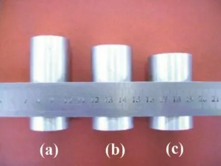
Fig.1.Designed initial blanks with different height-to-diameter ratios of(a) 2.25,(b)1.88 and(c)1.58.
After conventional grounding and polishing,specimens for microstructure observation were etched using a mixed solution of 5 g carbazotic acid,5 ml acetic acid,1 ml nitric acid and 100 ml water.Mean grain sizes were inspected using imagetool.Especially,preforms for optical morphology were water-quenched immediately to preserve the microstructure atelevated temperaturesafterpreheating,which were sectioned along the axial direction.The details for tensile tests and related specimen preparation are the same as Refs. [23,24].
2.Experimental procedure
A commercial AZ70(Mg-7.0Al-0.4Zn-0.2Mn)semicontinuously cast billet was used in this study.The cast billet was cut along the axial direction and machined into the initial forging blanks with constant volume but different height-to-diameter(H/D)ratios of 1.58,1.88 and 2.25, respectively(Fig.1).After homogenization at 673 K for 12 h, a two-step superplastic forging forming technology was used to obtain the high quality end products.The technology is described as follows.In the frst step,a preforming by a conventional forging process[7]was employed in an oil hydraulic press with the capacity of 3150 kN and constant crosshead speed of 8 mm/s to obtain fne-grained preforms available for SPF.The process parameters are 673 K and 1 s-1. A mixture of mineral oil and graphite powder was uniformly spray coated on the internal surface of female die and external surface of male die before forging for lubrication.Therefore, the pressed preforms via given sized blanks correspond to a determined compressive ratio.In the second step,the preforms were forged into end products at the high strain rate (1×10⁻²s-1)superplastic condition in the designed forging sets(Fig.2).In order to eliminate deformation microstructure and temperature gradient,all preforms were heated to the optimum SPF temperature of 653 K[23]with the holding time of 1.5,2,2.5 and 3 h,respectively.

Fig.2.Schematic illustration of forging sets for bullet shell:1 operating beam; 2,4,10 heat insulating plate;3 upper die holder;5 upper die;6 bottom die holder;7 bottom die;8 electrical resistance furnace;9 preform;11 operating console and 12 ejection lover.
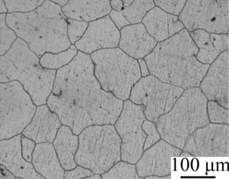
Fig.3.Microstructure of as-cast AZ70 magnesium alloy after homogenization.
3.Results and discussion
3.1.Effect of H/D ratio on microstructure of preform
The homogenized forging blanks with a mean grain size of 102±3 μm is shown in Fig.3.Because this coarse grain cannot meet the requirement for superplasticity[24],a simple preforming prior to the forging was applied to refne the grain size of the homogenized AZ70 magnesium alloy.In the frst step,all the homogenized forging blanks with different H/D ratios were performed in the same structural dies,as shown in Fig.4.The predominant grains of those preforms were various because of the different H/D ratios corresponding to different prestrain during preforming.A bimodal microstructure consisted of coarse deformed grains and fne DRX grains were observed in the preformed specimens.With increasing H/D ratio,the percent of DRX grains increases,the initial coarse grains are gradually nibbled,and grain size becomes uniform. According to the DRX map of AZ70 magnesium alloy,the DRX occurs when the plastic deformation is above the critical value[7].Because the stacking fault energy of magnesium alloys is smaller than that of a typical light metal[27],grain refnement by DRX readily occurs in magnesium alloys,and thus,hot deformation accompanied with DRX is a promising method for refning microstructure[7,12,28,29].However,the bimodal microstructure is not the reasonable microstructure for SPF.
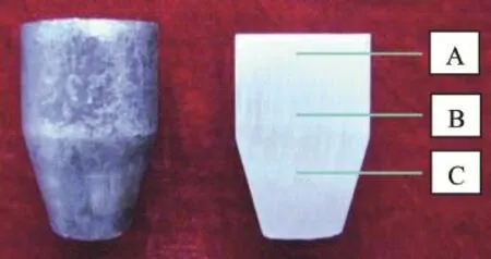
Fig.4.Picture of preform of AZ70 magnesium alloy.
Considering the requirement of SPF in the second step and the microstructure of the preform,it is necessary that the preform was preheated to 653 K with the holding time of 1 h at least.After 2 h heat treatment,specimens for microstructure examination were cut at three different locations of the preform,named A,B and C,as illustrated in Fig.4.The heat treated microstructure is revealed in Fig.5.Due to nonuniform deformation(small at the top and large at the bottom)in the preform with the low H/D ratio of 1.58,the coarse deformed grains was predominant at the locations A and B and fne recrystallized microstructure occurred at the location C.In other word,the grain size was uneven,i.e.,the small one is only~5 μm whereas the large one was~170 μm.With the H/D ratio increasing(H/D=1.88),the microstructures at the locations A,B and C trended to be uniform.Nevertheless,there still existed a few of coarse deformed grains.These results are good agreement with Guanet al.study[7].It is suggested that the microstructure evolution during deformation in semicontinuously cast AZ70 magnesium alloy obeys the following path,from initial complete deformed grains to subsequent partially recrystallized grains and fnal entirely recrystallized grains with increase of deformation degrees.On the other hand,the microstructure with a mean grain size~32 μm at the three locations was uniform and closely equiaxial grain with the H/D ratio of 2.25.
3.2.Effect of annealing time on microstructure of preform
The above results demonstrated that the preform corresponding to H/D ratio of 2.25 has uniform microstructure with fne equiaxial grains,which can approximately meet the requirement for SPF[24].Consequently,the preform was heat treated to further optimize annealing time and investigate the possibility of grain growth.The heat treated microstructures at different annealing times are shown in Fig.6.These microstructures mainly combined of deformed and recrystallized grains,and recrystallized grains gradually increased with increasing of annealing time.Zigzag grain boundary was observed after heat treatment at 653 K for 1.5 h(Fig.6a), which indicates the recrystallization is not complete.On the other hand,completely recrystallized grains that exhibited uniform microstructure with a mean grain size of 29-34 μm were obtained at the annealing time of 2-2.5 h(Fig.6b and c). However,grains trended to grow up obviously at the annealing time of 3 h with a mean grain size of 39 μm(Fig.6d). Therefore,annealing time should be controlled between 2 and 3 h in order to obtain the required microstructure for SPF[24].
3.3.Superplastic forging
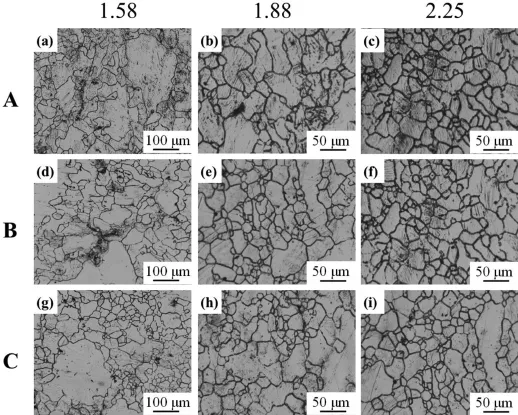
Fig.5.Microstructure at different locations of the preforms.Location A(a,b,c),location B(d,e,f)and location C(g,h,i)for H/D=1.58,1.88,2.25,respectively.
Prior to the superplastic forging,mechanical properties according to the various strain rates and grain sizes at 653 K were investigated using the tensile tests.It was found that the maximum elongation of 191.5%was achieved at the strain rate of 1×10⁻³s-1and the elongation to failure at high strain rate of 1×10⁻²s-1still kept a high level(161.5%)with a grain size of 14 μm[23].However,the maximum elongation dramatically decreased when the strain rate is higher than 1×10⁻²s-1.Furthermore,maximum elongations of 125% and 122%were obtained at a strain rate of 1×10⁻³s-1for the specimens with grain sizes of 37 and 41 μm,respectively. This implies that we can employ the forging at the range of 1×10⁻³s-1-1×10⁻²s-1,as shown in the shaded area ofFig.7.Therefore,it is possible to forge the bullet shell at the higher strain range.
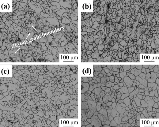
Fig.6.Microstructure of preform with H/D=2.25 after heat treatment at different times 1.5 h(a),2 h(b),2.5 h(c)and 3 h(d).
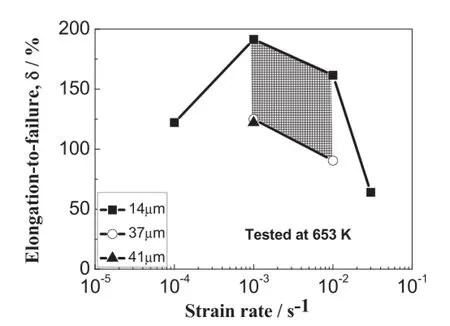
Fig.7.Maximum elongation with different grain size(14 μm[23],37 μm and 41 μm)dependence of strain rates at 653 K.
In the second step,the forging sets for superplastic forging were designed(Fig.2).In order to improve the forming productivity,the optimum superplastic forging of the bullet shell was conducted under the high strain rate condition,i.e.653 K and 1×10⁻²s-1,as close as possible.The forged bullet shell using semi-continuously cast AZ70 magnesium alloy is shown in Fig.8.It was diffcult to forge and only a few of preforms was forged into end products when the H/D ratio of the initial blank is 1.58.In addition,all of the end products showed fractures on the surface due to coarse and uniform microstructure of the preforms.With the increase of H/D ratio(H/ D=1.88),the bullet shell surface had been greatly improved (H/D=1.88).However,minor fracture still occurred in the localized surface(Fig.8a).On the other hand,the forged bullet shell showed high-quality surface without fracture(Fig.8b) when the H/D ratio is 2.25.It is associated with the uniform microstructure of preforms that is close to the one required for SPF.It is indicated that the quality of the forged bullet shell is improved with the increase of H/D ratio.Nevertheless,higher H/D ratio(above 2.5)leads to the destabilization during upsetting.Consequently,it is reasonable that the H/D ratio of the initial blanks is controlled between 2.0 and 2.5 for AZ70 bullet shell superplastic forging.
Fig.9 shows the microstructure perpendicular to axial direction of the superplastic forged bullet shell via the heat treatment states of F,O and T6.The microstructure of the superplastic forged AZ70 bullet shell exhibited fne and equiaxial recrystallized grains(Fig.9a),which relaxed the anisotropy compared with conventional die-forging parts.By heat treatment,the microstructure of the end products at O state showed uniform and fne equiaxial grains with a mean grain size of 15.3 μm(Fig.9b).On the other hand,uniform and fne equiaxial grains(15.1 μm)were retained and amount of precipitated phase distributes diffusely the inner of grains at T6 state(Fig.9c),implied the best combined mechanical properties[7,30].This is confrmed by hardness measurement and tensile test.The best combined mechanical properties of the superplastic forged AZ70 bullet shell are δ=14.3%, σb=316 MPa and HB=67.2 that are obtained at T6 state,as shown in Fig.10.
In summary,a bullet shell produced by directly using semicontinuously cast AZ70 magnesium alloy possessing desired defect-free microstructure and good mechanical properties is successfully obtained.Remarkably,in comparison with the same structural Al alloy,the AZ70 bullet shell can realize aweight saving of~30%and meet the possible needs for further short range and more precise trajectory[7].

Fig.8.AZ70 bullet shell of H/D=1.88(a)and H/D=2.25(b)using superplastic forging forming.

Fig.9.Microstructure of end products at F(a),O(b)and T6(b)state.
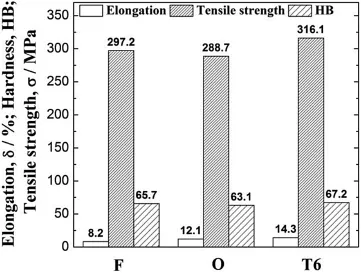
Fig.10.Mechanical properties of end products.
4.Conclusions
(1)It is suggested that the H/D ratio of the initial blank is controlled between 2.0 and 2.5 and annealing time for the preform is controlled between 2 and 3 h.
(2)The“two-step superplastic forging forming of semicontinuously cast AZ70 magnesium alloy”technology is effective to fabricate large deformation magnesium alloy parts.The bullet shell with high quality surface and good microstructure wasformed using quick preforming and subsequentsuperplastic forging.The forged bullet shell produced by directly using semicontinuously cast AZ70 magnesium alloy possesses desired defect-free microstructure and good mechanical properties,and realize 30%weight saving and meet possible needs for further shot range and more precise in comparison with the same component produced with structural Al alloy.
Acknowledgements
The National Natural Science Foundation of China(No. 51171174)and the National Key Technology R&D Program of China(No.2012BAI18B01)supported this study.
[1]Z.Horita,K.Matsubara,K.Makii,T.G.Langdon,Scr.Mater.47(2002) 255-260.http://dx.doi.org/10.1016/S1359-6462(02)00135-5.
[2]F.C.Liu,Z.Y.Ma,M.J.Tan,Metall.Mater.Trans.A(2013)1-14.
[3]B.Mordike,T.Ebert,Mater.Sci.Eng.A 302(2001)37-45.
[4]S.K.Guan,L.H.Wu,L.G.Wang,Trans.Nonferrous Met.Soc.18(2008) 315-320.http://dx.doi.org/10.1016/S1003-6326(08)60055-2.
[5]N.Ogawa,M.Shiomi,K.Osakada,Int.J.Mach.Tool.Manuf.42(2002) 607-614.http://dx.doi.org/10.1016/S0890-6955(01)00149-3.
[6]B.A.Behrens,I.Schmidt,J.Mater.Process Tech.187-188(2007) 761-765.http://dx.doi.org/10.1016/j.jmatprotec.2006.11.057.
[7]S.Guan,L.Wu,P.Wang,Mater.Sci.Eng.A 499(2009)187-191.
[8]V.Wesling,T.Ryspaev,A.Schram,Mater.Sci.Eng.A 462(2007) 144-148.
[9]X.Zhang,L.Li,Y.Deng,N.Zhou,J.Alloy.Compd.481(2009) 296-300.http://dx.doi.org/10.1016/j.jallcom.2009.03.166.
[10]X.Wu,Y.Liu,Scr.Mater.46(2002)269-274.
[11]A.Mohan,S.Panigrahi,R.Mishra,R.Verma,J.Mater.Sci.48(2013) 5633-5644.
[12]A.Bussiba,A.Ben Artzy,A.Shtechman,S.Ifergan,M.Kupiec,Mater. Sci.Eng.A 302(2001)56-62.
[13]H.Somekawa,H.Watanabe,T.Mukai,K.Higashi,Scr.Mater.48(2003) 1249-1254.http://dx.doi.org/10.1016/S1359-6462(03)00054-X.
[14]H.Watanabe,T.Mukai,M.Mabuchi,K.Higashi,Scr.Mater.41(1999) 209-213.http://dx.doi.org/10.1016/S1359-6462(99)00155-4.
[15]Y.H.Wei,Q.D.Wang,Y.P.Zhu,et al.,Mater.Sci.Eng.A 360(2003) 107-115.http://dx.doi.org/10.1016/S0921-5093(03)00407-6.
[16]Z.Ma,F.Liu,R.Mishra,Acta Mater.58(2010)4693-4704.
[17]A.Mohan,W.Yuan,R.Mishra,Mater.Sci.Eng.A 562(2013)69-76.
[18]F.Chai,D.Zhang,W.Zhang,Y.Li,Mater.Sci.Eng.A 590(2014) 80-87.
[19]F.Chai,D.Zhang,Y.Li,W.Zhang,Mater.Sci.Eng.A 568(2013) 40-48.
[20]W.Kim,W.Kim,Mater.Sci.Eng.A 594(2014)189-192.
[21]C.Y.Lin,H.Y.Bor,C.G.Chao,T.F.Liu,J.Alloy.Compd.556(2013) 26-31.
[22]M.Kai,Z.Horita,T.G.Langdon,Mater.Sci.Eng.A 488(2008) 117-124.http://dx.doi.org/10.1016/j.msea.2007.12.046.
[23]L.Wu,L.Wang,P.Wang,S.Guan,Rare Met.Mater.Eng.39(2010) 194-198.
[24]P.Wang,L.H.Wu,S.K.Guan,Trans Nonferrous Met.Soc.20(2010) s527-s532.
[25]L.Wu,T.Wang,P.Wang,L.Wang,S.Guan,Rare Met.Mater.Eng.40 (2011)1887-1890.http://dx.doi.org/10.1016/S1875-5372(12)60008-3.
[26]T.Mohri,M.Mabuchi,M.Nakamura,et al.,Mater.Sci.Eng.A 290 (2000)139-144.http://dx.doi.org/10.1016/S0921-5093(00)00959-X.
[27]D.Sastry,Y.Prasad,K.Vasu,Scr.Metall.3(1969)927-929.
[28]H.Watanabe,H.Tsutsui,T.Mukai,M.Kohzu,S.Tanabe,K.Higashi, Int.J.Plast.17(2001)387-397.http://dx.doi.org/10.1016/S0749-6419(00)00042-5.
[29]L.Tang,C.Liu,Z.Chen,D.Ji,H.Xiao,Mater.Des.50(2013)587-596. http://dx.doi.org/10.1016/j.matdes.2013.03.054.
[30]Q.Peng,X.Hou,L.Wang,Y.Wu,Z.Cao,L.Wang,Mater.Des.30 (2009)292-296.http://dx.doi.org/10.1016/j.matdes.2008.04.069.
Received 12 November 2014;revised 25 November 2014;accepted 3 December 2014 Available online 31 January 2015
*Corresponding authors.Tel./fax:+86 371 67780051.
E-mail addresses:wangpangh@163.com(P.Wang),skguan01@163.com (S.Guan).
Peer review under responsibility of National Engineering Research Center for Magnesium Alloys of China,Chongqing University.
http://dx.doi.org/10.1016/j.jma.2014.12.004.
2213-9567/Copyright 2015,National Engineering Research Center for Magnesium Alloys of China,Chongqing University.Production and hosting by Elsevier B.V.All rights reserved.
Copyright 2015,National Engineering Research Center for Magnesium Alloys of China,Chongqing University.Production and hosting by Elsevier B.V.All rights reserved.
 Journal of Magnesium and Alloys2015年1期
- Journal of Magnesium and Alloys的其它文章
- Improved mechanical proprieties of“magnesium based composites”with titanium-aluminum hybrids
- Effect of single Si1-xCxcoating and compound coatings on the thermal conductivity and corrosion resistance of Mg-3Sn alloy
- Investigation on mechanical properties and creep behavior of stir cast AZ91-SiCpcomposites
- Effect of microstructure evolution on mechanical property of extruded Mg-12Gd-2Er-1Zn-0.6Zr alloys
- Effects of Bi on the microstructure and mechanical property of ZK60 alloy
- Multi-response optimization of process parameters in friction stir welded AM20 magnesium alloy by Taguchi grey relational analysis