
Modeling and simulation of turbofan engine based on equilibrium manifold
2015-03-04 06:18MUChunyangLIShizhongLIHua
MU Chun-yang, LI Shi-zhong, LI Hua
(1. School of Mechatronics Engineering, North University of China, Taiyuan 030051, China;2. Inner Mongolia Longsheng Construction & Installation Co., Ltd., Baotou 014030, China)
Modeling and simulation of turbofan engine based on equilibrium manifold
MU Chun-yang1, LI Shi-zhong1, LI Hua2
(1.SchoolofMechatronicsEngineering,NorthUniversityofChina,Taiyuan030051,China;2.InnerMongoliaLongshengConstruction&InstallationCo.,Ltd.,Baotou014030,China)
Because the normal operation of the engine is located near the equilibrium manifold,the method of equilibrium manifold nonlinear dynamic modeling is adopted for turbofan engine more than the local train modeling. The method studies the system characteristics near the equilibrium manifold. The modeling method can be realized through dynamic and static two-step, and for the specific parameter modeling steps and algorithm are given. The output of the test data is compared with the model output through numerical simulation,to check the model with an additional set of test data. The simulation results show that the model has reached the requirements of engineering accuracy.
equilibrium manifold; turbofan engine; modeling; simulation
Engine design needs to establish a mathematical model firstly for simulation, which is a commonly used method. The establishment of mathematical model has many advantages, such as cost reduction, prevention of accidents, and so on[1-2].
A lot of research about the above idle condition of engine modeling has been done and a variety of modeling methods are put forward. The component modeling method based on aerodynamic and thermodynamic principle can accurately reflect the engine’s actual heat and aerodynamic characteristics, but it requires a great deal of calculation to solve the differential equation[3]. In multivariable case, using the method, calculation is quite complex, and the algorithm is not very stable and has poor accuracy[4]. In recent years, neural network has provided the possibility due to the establishment of engine’s nonlinear dynamic model for its strong nonlinear approximation ability[5]. But this method also has drawbacks, i.e. it is a “black box” modeling method for new projects, which affects its application in the engineering field.
In this paper, nonlinear dynamic model of the engine based on equilibrium manifold method is established. Equilibrium manifold is steady state operating points set of the nonlinear system. Considering the engine’s operational safety, the design of the control strategies over temperature, speed and anti-surge can ensure that the normal operation state of the engine is in a small area equilibrium manifold. Because spatial dimensionality in this area is much smaller than the space dimensionality of the overall state of the engine, a high-dimensional engine modeling problem is converted into several low-dimensional modeling problems. Finally, the simulation shows that the method is simple and can reach engineering accuracy.
1 Theory base
For anm-in-m-out nonlinear system of biaxial turbofan engine with

(1)
wheref(·,·) andh(·,·) are smooth vector functions,u∈Rm, y∈Rm.Theequilibriummanifoldofthenonlinearsystem(1)isaset,
(2)
Inpractice,theequilibriummanifoldreferstothestablepointssetofthesystem(namely,state,inputandoutputpoints).Forthenonlinearsystem(1),theequilibriummanifoldcanbeparameterizedas
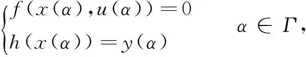
(3)
whereΓisanopensetofRm.Thesmalldeviationsapproximatelinearizationfamilyofequilibriummanifoldcanbewrittenas
,


α∈Γ⊆Rm.
As seen from the above equation, the nonlinear system (1) is expanded on the equilibrium manifold, small deviations linearization family is still a non-linear system. When modeling, Eq.(4) can be realized through static and dynamic methods. Static modeling obtains the equilibrium manifold(x(α),y(α) andu(α)), and dynamic modeling gets partial derivative term (A(α),B(α),C(α) andD(α)).
2 Modeling method
2.1 Determination of model state, input and output variables
Without considering the effect of heat inertia, for two-axis two-bypass turbofan engine, energy storage components have both high and low pressure rotors, thus high and low pressure rotors’ speedsNhandNlcan be taken as the model state variables, taking into account the effects of flow conditions on engine operating conditions with conversion speed. When there is no additional energy input, model input is only fuel flowqmf; The outputs of the model include high and low pressure rotor speedsNhandNl, the total pressure behind compressorPt3and the total temperature behind high-pressure turbineTt5, etc.
2.2 Mathematical model
Because high pressure rotor speedNhhas the largest effect on the working state of the turbofan engine, therefore, the parameterαin Eq.(4) is selected to beNh. Using the converted variables, the mathematical model of turbofan engine expanded near the equilibrium manifold can be expressed as
(5)

whereg1(Nh)=qmfc(Nh) andg2(Nh)=Nl(Nh) are the system equilibrium manifold projections in different subspaces;k11(Nh),k12(Nh),k21(Nh) andk22(Nh) are the partial derivation items before state variables.yicis equivalent values of other output parameters (Pt3,Tt5, etc.);yic(Nh) corresponds to equilibrium manifold of output parameters;ki1(Nh) andki2(Nh) correspond to the partial derivative terms of output parameters.
It should be noted that the model structure in Eq.(5) is only suitable for the engine modeling of equilibrium manifold above idle process.
2.3 Modeling steps and algorithms
According to Eqs.(1)-(5), after the establishment of the function relationship between the equilibrium manifold and partial derivative term, the model being suitable for turbofan engine operation is established by means of two steps, that is, static modeling determines the equilibrium manifold, and dynamic modeling determines the partial derivative term. For the turbofan engine under discussion, the two steps can be accomplished by using the least square identification method. The specific steps and algorithm are as follows:
1) Determination of the equilibrium manifold (static modeling)
It can be seen from Eq.(5) that the equilibrium manifolds (g1(Nh),g2(Nh) andyic(Nh)) are a single variable function of high-pressure rotor speedNh. First, the structure of the equilibrium manifold is determined as polynomial structure because theoretically polynomial can approximate to continuous function with arbitrary precision. Using steady state operating points from experimental data and least square identification method, polynomial coefficients can be got.
2) Determination of partial derivative term (dynamic modeling)
It can be assumed that the partial derivative term is polynomial structure. Based on the equilibrium manifold function relation determined by static modeling and the output measured by acceleration or test, according to least square identification method, the partial derivation polynomial parameters are identified. Taking the high pressure rotor speed model above idle process as an example, the algorithm is given as follows:
①k11(Nh),k12(Nh) are determined as a linear polynomial structure,
② Calculating high-pressure rotor accelerationanhc, the high-pressure rotor model equation are rewritten as
(6)
where Δqmfc=qmfc-g1(Nh), Δnlc=nlc-g2(Nh).
Eq.(6) can also be written in matrix form,
(7)
③ According to the experimental data, using least square algorithm, the unknown coefficientb11,c11,b12andc12are identified, thus the function relationship of the partial derivative term is determined.
3 Numerical simulation
For adjustment process in practical working condition, two groups of comparison results between ground test data and simulation output data of engine are given.
Under standard atmospheric condition, this turbofan engine is tested, Fig.1 shows the simulation curve of the nonlinear model, in whichnis high pressure rotor speed of the engine andqmfis input of fuel flow.
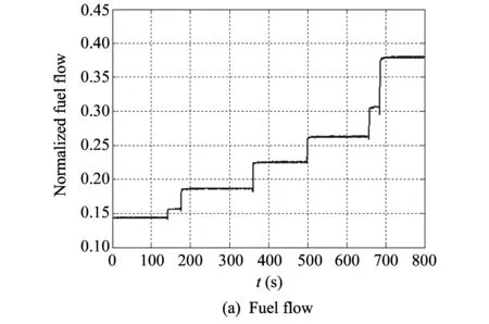

Fig.1 Test data of engine in factory
We performed corresponding processing on stable data, several equilibrium points are obtained. After fitting, equilibrium manifold is shown in Figs.2-5.
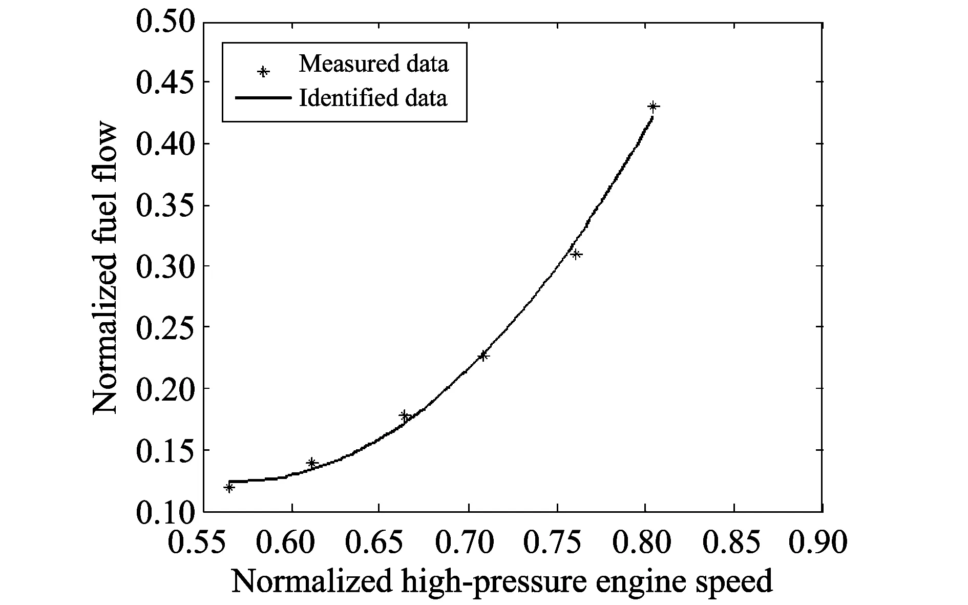
Fig.2 Turbofan engine equilibrium manifold
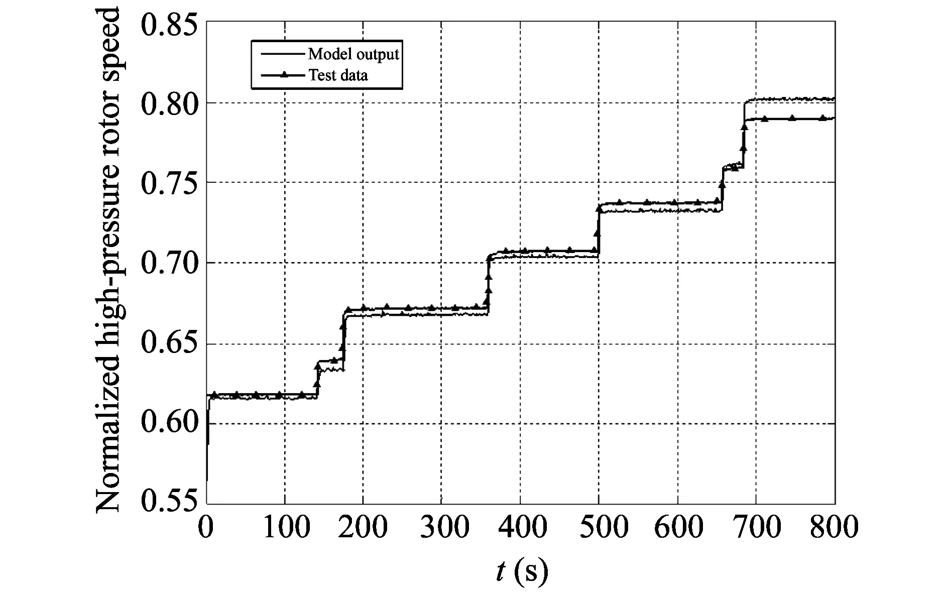
Fig.3 High-pressure rotor speed
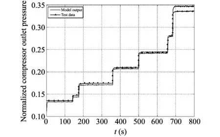
Fig.4 Compressor outlet total pressure
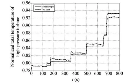
Fig.5 Total temperatures behind high-pressure turbine
Using the test data from another to verify the model, the model input is shown in Figs.6-9.

Fig.6 Fuel flow input
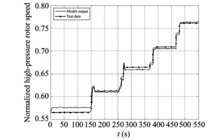
Fig.7 High-pressure rotor speed
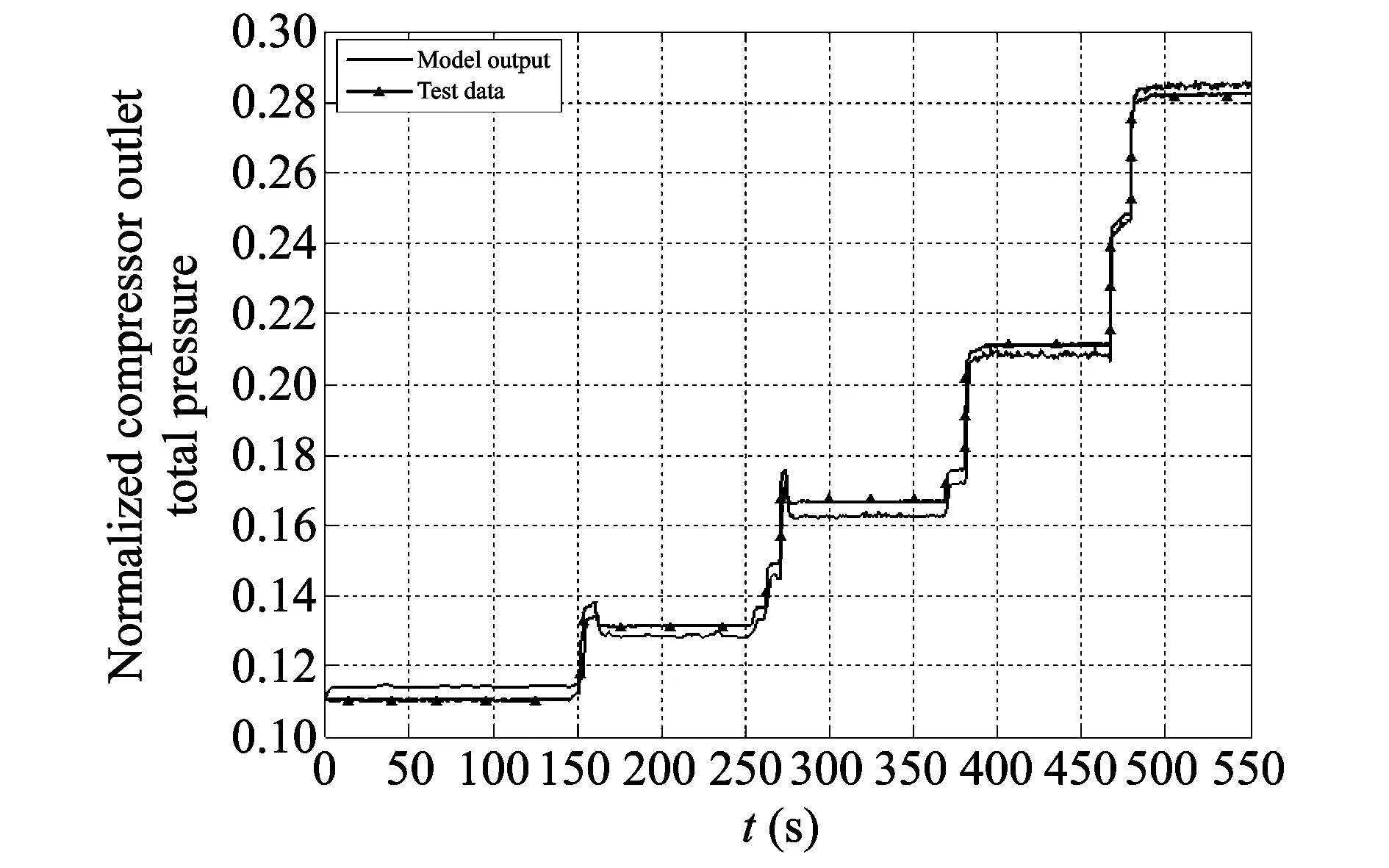
Fig.8 Compressor outlet total pressure
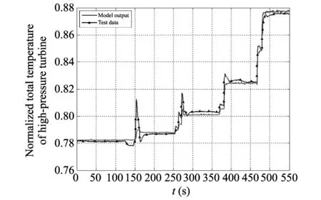
Fig.9 Total temperature behind high pressure turbine
4 Conclusion
In this paper, based on the equilibrium manifold modeling theory of the nonlinear system, the model of a turbofan engine is established only using test data but detailed component characteristics. The identification method is adopted to establish a simplified model of the engine. Finally, the engine test process is simulated and the model is verified by another factory test data. The results are in good agreement with the test data, laying the foundation for the subsequent controller design.
[1] HU Wei-hong, LI Shu-qing, SUN Jian-guo. Real-time simulation model for a turbofan engine based on nonlinear system equilibrium manifold theory. Journal of Aerospace Power, 2010, 25(1): 213-217.
[2] CHENG Guo. Vibration modeling and analysis for dual-rotor aero-engine. Journal of Vibration Engineering, 2011, 24(6): 619-632
[3] SUI Yan-feng, YU Da-ren. Identification of expansion model based on equilibrium manifold of turbojet engine. Acta Aeronautica et Astronautica Sinica, 2007, 28(3): 531-534.
[4] XIA Chao,WANG Ji-qiang, SHANG Guo-jun, et al. Component-level modeling and analysis of aeroengine based on Matlab/Simulink. Aircraft Engine, 2012, 38(4): 31-33.
[5] LIAO Zi-li, XIANG Yu, LIU Chun-guang, et al. Modeling and simulation research on engine for electric drive vehicle based on neural network. Fire and Command Control, 2013, (12): 100-103.
基于平衡流形的涡扇发动机建模仿真
牟春阳1, 李世中1, 李 华2
(1. 中北大学 机电工程学院,山西 太原 030051; 2. 内蒙古隆升建筑安装工程有限公司, 内蒙古 包头 014030)
考虑到发动机正常工作状态基本位于其平衡流形的附近, 因此采用平衡流形非线性动态建模方法对涡扇发动机慢车以上工况进行建模, 以便研究平衡流形附近系统特性。 该建模方法可通过动静两步法加以实现, 并针对具体参数给出了建模的步骤和算法。 最后通过数值仿真将试验数据的输出与模型的输出进行对比, 用另外一组试验数据对模型进行校核。 仿真结果表明, 该模型达到了工程精度要求。
平衡流形; 涡扇发动机; 建模; 仿真
MU Chun-yang, LI Shi-zhong, LI Hua. Modeling and simulation of turbofan engine based on equilibrium manifold. Journal of Measurement Science and Instrumentation, 2015, 6(2): 180-184.
10.3969/j.issn.1674-8042.2015.02.012
MU Chun-yang (610440605@qq.com)
1674-8042(2015)02-0180-05 doi: 10.3969/j.issn.1674-8042.2015.02.012
Received date: 2015-04-06
CLD number: TK441 Document code: A
猜你喜欢
云南画报(2021年9期)2021-12-02
无机化学学报(2021年7期)2021-07-10
科学导报(2021年91期)2021-01-11
中北大学学报(自然科学版)(2019年6期)2019-11-22
无机化学学报(2019年5期)2019-05-07
中国经贸聚焦(2017年12期)2017-12-20
装备制造技术(2016年5期)2016-09-10
铁道通信信号(2016年6期)2016-06-01
北京航空航天大学学报(2016年12期)2016-02-27
燃气涡轮试验与研究(2011年1期)2011-04-16
 Journal of Measurement Science and Instrumentation2015年2期
- Journal of Measurement Science and Instrumentation的其它文章
- Prouhet-Thue-Morse sequence and atomic functions in applications of physics and techniques
- Rapidly determining fuel pollution level of aviation lubricating oil 50-1-4Φ by mid-infrared spectrometry
- Fuzzy PID control system for hose pulse experiment based on LabVIEW
- Design of handheld terminal for shock wave pressure measurement system
- Modelling and simulation of high-speed milling chatter regeneration based on MATLAB
- Use of online electrical conductivity meter to monitor cold decomposition of carnallite