
Effect of Tip-Blade Cutting on the Performance of Large Scale Axial Fan
2015-03-21 05:09尹超胡骏严伟张晨凯
(尹超), (胡骏), (严伟), (张晨凯)
Jiangsu Province Key Laboratory of Aerospace Power Systems, College of Energy and Power, Nanjing University of Aeronautics and Astronautics, Nanjing 210016, P.R. China (Received 4 November 2014; revised 24 March 2015; accepted 25 May 2015)
Effect of Tip-Blade Cutting on the Performance of Large Scale Axial Fan
YinChao(尹超),HuJun(胡骏)*,YanWei(严伟),ZhangChenkai(张晨凯)
Jiangsu Province Key Laboratory of Aerospace Power Systems, College of Energy and Power, Nanjing University of Aeronautics and Astronautics, Nanjing 210016, P.R. China (Received 4 November 2014; revised 24 March 2015; accepted 25 May 2015)
The effect of tip-blade cutting on the performance of a large scale axial fan was investigated using computational fluid dynamics (CFD) methods. Experiments verified the numerical simulations. The original fan was compared with the one with tip-cutting in terms of dimensionless characteristic and aerodynamic performance in tip region under the conditions of the maximum efficiency point and near-stall point. The results showed that double leakage flow occurred in tip clearance at maximum efficiency point and spillage of leakage flow from leading edge occurred in tip-blade region at near-stall point for the both two fans; and that tip-cutting with 6% of blade height could reduce the intensity of tip-leakage vortex and increase flow capacity in tip blade region, and hold the stall margin almost the same as the original fan. The maximum efficiency of the fan with tip-cutting was improved by 1%, and the ability of total pressure rising was obviously greater than the original fan.
large axial fan; tip-blade cutting; numerical simulation; tip-leakage vortex; flow capacity
0 Introduction
Large axial ventilated fan is critical for cooling tower in electric power plant. In practice, a fixed fan series cannot perfectly fit all working environments. When a certain fan is a bit larger than the requirement, it is wise to cut the blade tip to avoid costly redesigning. Tip-cutting can change the flow range and even the pressure range when combined together with blade number change. Therefore, a certain fan mold can be transformed into a series of fans, which greatly decreases production cost and improves the manageability of quality. However, tip-cutting brings about problems of dynamic performance and stability, which need further investigation.
Tip-cutting is a way of tip-treating, and many researchers have focused on tip-treating for compressor. Zhong Jingjun et al.[1]used a blade tip winglet to control the secondary flow and found that the winglet was the most effective one to weaken the intensity of the leakage flow. Shao Weiwei et al.[2]condacted some parameter studies on different attenuation thicknesses and relative height of pressure surface at tip region and indicated that blade tip attenuation within a certain range could advance choke mass flow, total pressure ratio and adiabatic efficiency. Yuan Wei et al.[3]analyzed the effect between tip clearance and casing treatment in turbomachinery, while many researchers emphasized the effect of changing tip clearance on the performance of axial compressor. Lakshminarayana et al.[4]measured the relative stagnation pressure losses in the tip region of a single-stage axial-flow compressor and suggested that the tip clearance losses increased with an increase of pressure-rise coefficient. Inoue et al.[5]measured the rotor exit flow near the rotor tip and clarified the behavior of tip leakage vortex for various tip clearances. Qiu Ming et al.[6]used a numerical optimization method for aerodynamic design of compressor blade. In his research, arbitrary rotary surface blade profiles and 3-D blade were developed for a small axial compressor with high pressure ratio. When the designed rotor reached a given pressure ratio and a mass flow rate, it had a relatively high efficiency and a large stabilization working range.
The flow in axial ventilation fan is exactly the same with that of low speed axial compressor. However, as its total pressure ratio is smaller, its rotational speed is lower and its fan blade number is fewer. Ventilation fan and compressor have some similarities and some differences. Wang Jun et al.[7]investigated the influence of tip clearance on external performance and tip leakage vortex of low-pressure axial fan, and found that with the increase of tip clearance, the leakage flow disappeared, and was replaced by leakage vortex. Zhu Xiaocheng et al.[8]launched an experimental study on the tip leakage flow of an axial fan and found that for the ventilation fan with low speed and low pressure, the tip leakage flow also had a chance to roll up into a discrete vortex at three different tip clearances.
Obviously, tip-cutting is different from tip clearance changing, but few researchers have paid attention to tip-cutting for axial fan. Lv Feng et al.[9]preliminarily studied the blade cutting effects on the performance of large axial-flow fan, and found that for the cases of hub-tip ratio changing from 0.56 to 0.65, the dimensionless characteristics of original fan could still be used for performance prediction of the blade-cut fans. However, they did not provide the influence and mechanism of blade-cutting on the performance of large axial fan at all.
Therefore, the characteristics of large axial ventilation fans both with and without tip-cutting are investigated in detail. Moreover, tip flow fields of the two fans are numerically investigated to elucidate the loss generation mechanism.
1 Numerical Study
1.1 Description of the fan and tip-cutting
A large low-speed axial-flow original fan is shown in Fig.1(a), and its design specifications are listed in Table 1. The fan has no stator, and its rotor tip diameter is 8 450 mm with a tip clearance of 25 mm. The hub-tip ratio is 0.142 and the number of rotor blades is 8. The design stagger angle of the fan is 26°.
Due to size limit of cooling tower, the original fan blade (marked as A in Fig.1(b)) is cut by 250 mm, which is 6% of the blade length. The new tip-cutting fan (marked as B in Fig.1(b)) holds the same tip clearance as fan A, and its hub-tip ratio is up to 0.151. Fig.1(b) shows the geometry comparison of the two fan blades.
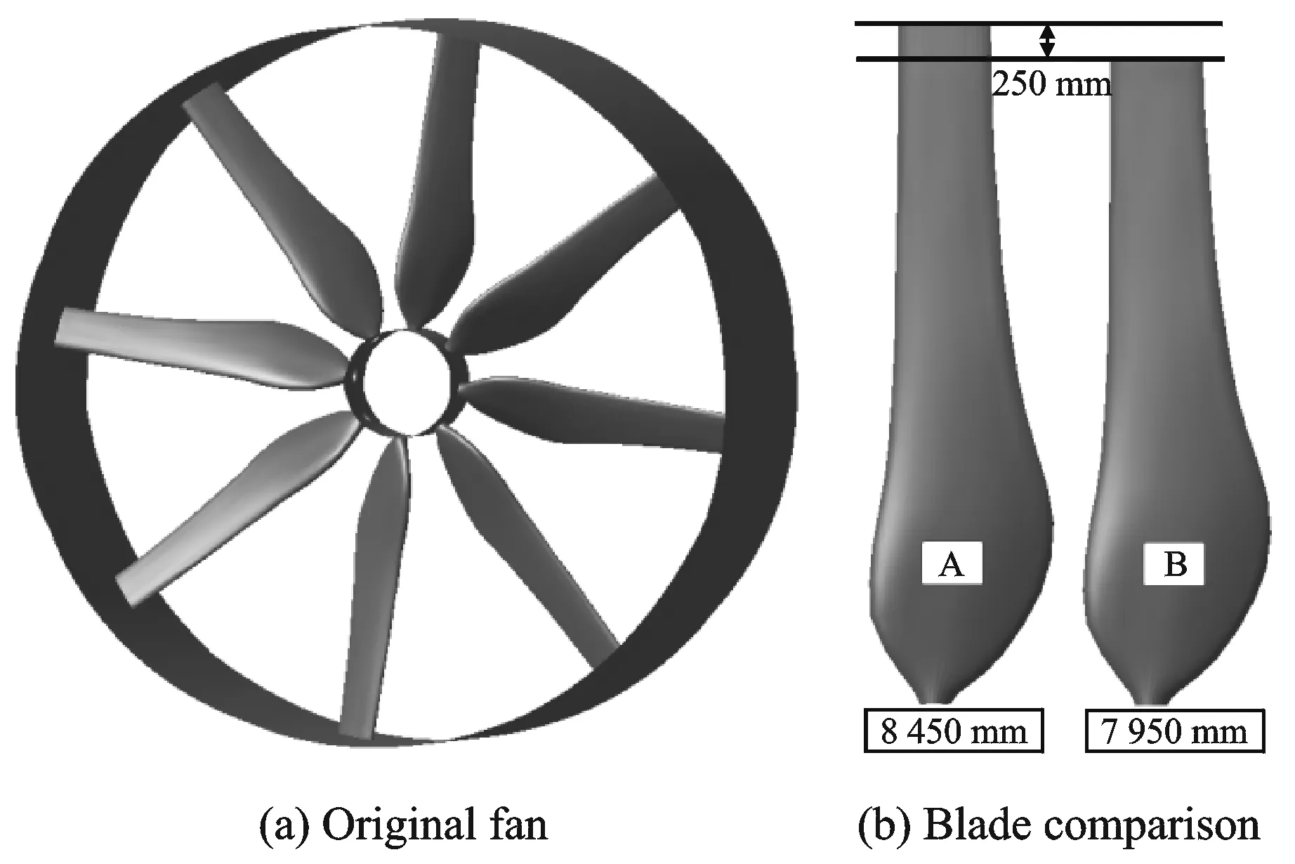
Fig.1 Original geometry of the fan and blade comparison
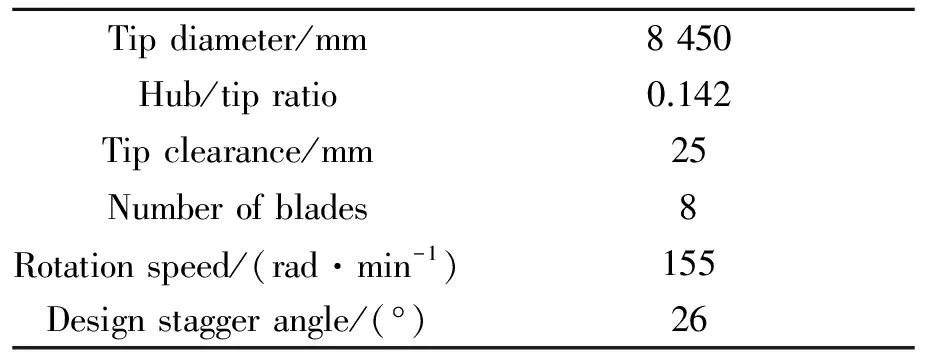
Tipdiameter/mm8450Hub/tipratio0.142Tipclearance/mm25Numberofblades8Rotationspeed/(rad·min-1)155Designstaggerangle/(°)26
1.2 Numerical algorithm
Fig.2 shows the computational domain and model for this study. The inlet boundary is placed one blade height upstream from the rotor center, and the outlet boundary is placed one and a half blade heights downstream from the rotor center.
The computational grid is generated using the NUMECA AutoGrid5TM(Automated Grid Generator). The grid in tip clearance consists of 17 nodes in the span-wise direction. The grid in one blade passage contained 2 019 125 nodes. The minimum grid space asy+<3 is on the walls.
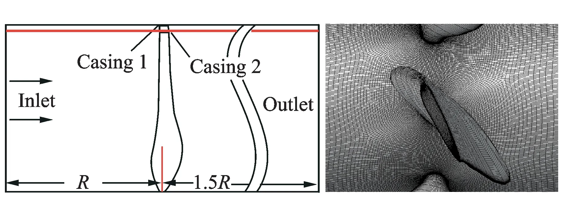
Fig.2 Fan meridian computational domain and blade surface mesh
Three-dimensional compressible steady RANS simulations are carried out using the commercial code NUMECA FINETM. A Spalart-Allmaras turbulence model is applied. The total pressure is 101 325 Pa. Total temperature is 288.15 K. And axial inlet flow angle is specified at the inlet boundary. The radial equilibrium static pressure is specified at the outlet boundary. The air mass flow rate change with the outlet static pressure.
The fan shaft power can be obtained as[10]

(1)
Total pressure rise of the fan is defined as the difference between the total pressure of the outlet and that of the inlet
(2)
where the subscripts ″in″ and ″out″ denote the plane close to the leading and the trailing edges of the fan blade, respectively.
Total pressure efficiency of the fan is defined as
(3)
The flow coefficient is defined as
(4)
The total pressure coefficient is defined as
(5)
whereQis the volume flow rate,UandAare the tip blade tangential speed and the through flow area, respectively.
2 Validation of Numerical Simulation
Due to its large scale, it is too costly to test the original fan, but there is an alternative. Similarity theory[10]illustrates that if two fans are similar in geometry, their dimensionless characteristics are equal with a same flow coefficient, no matter what their scales or rotational speeds are. Therefore, we develop a geometry-similar fan with fan B by reducing the diameter from 8 to 1.6 m, then test the new fan′s performance.
The tip chord to blade height ratio of fan B is 0.131, same with its geometry-similar fan. The new fan′s stagger angle is 18°, same with the numerical simulation for fan B. The rotational speed of the test fan is 730 rad/min; while that of fan B is 155 rad/min.
Fig.3 shows the comparisons between test and CFD results in terms of flow coefficient-efficiency recation and flow coefficient-total pressure coefficient relation. Fig.3(a) shows that although the test curve shifts to the left of the CFD curve, there are still at least 4 test points match well with the CFD results, and the max efficiency error is less than 3%. Fig.3(b) shows the same tendancy. This validates the reliability of the numerical simulations.
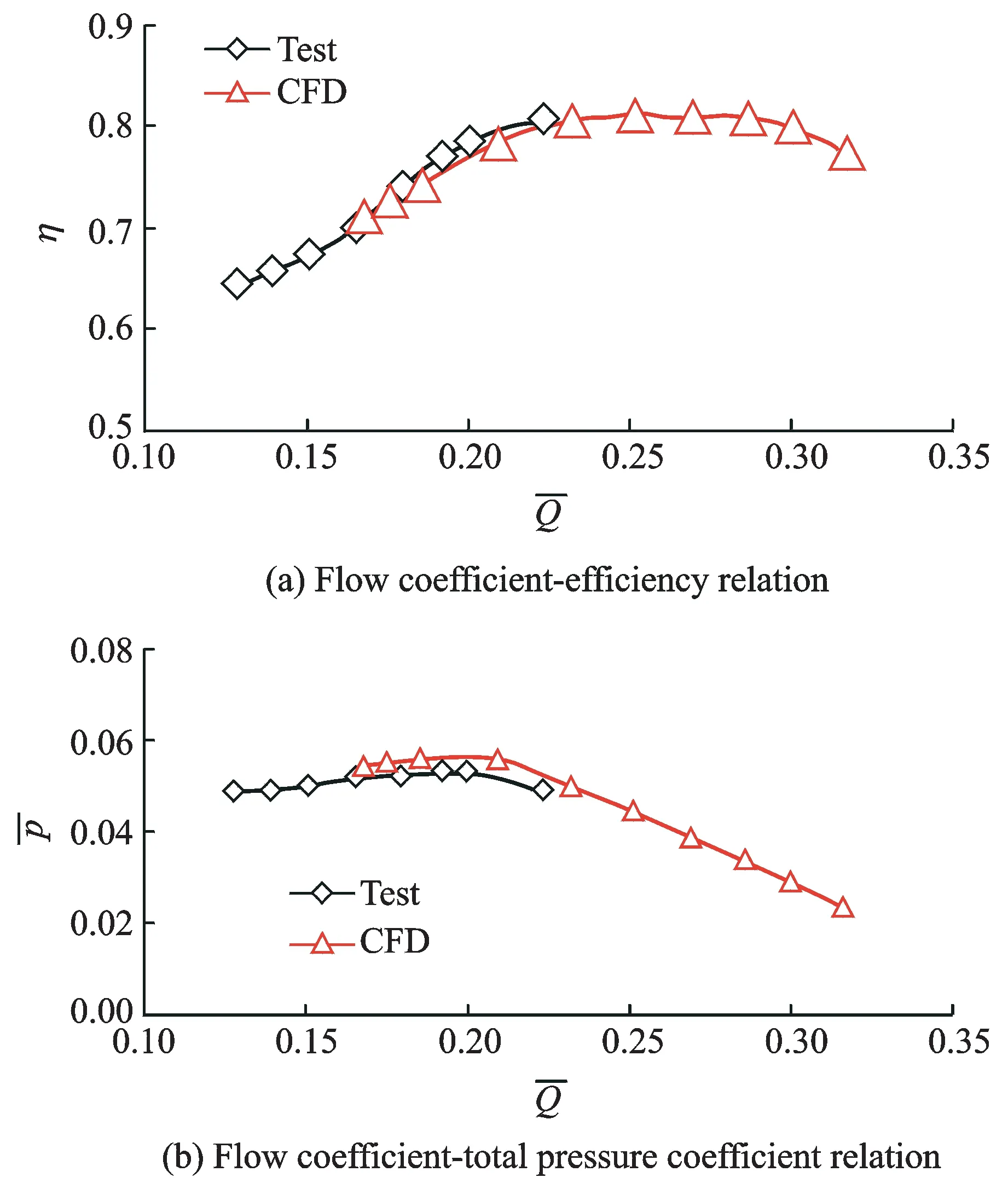
Fig.3 Dimensionless characteristic comparison between test and CFD results
3 Discussions and Analyses
3.1 Characteristic comparison
Since there is no geometry similarity between the two fans, dimensionless parameters are needed to compare the two fans′ performances[10]. Comparisons between the two fans in terms of efficiency and total pressure coefficient characteristics are shown in Fig.4. All computed results are steady-state simulations. A near-stall point is set as ″solution limit″ to prevent the simulation converging to steady state.
Fig.4(a) shows that flow coefficient and efficiency curves of the two fans exibit almost the same tendency at the near-stall point, i.e. the solution limit, indicating that cutting off 6% of blade cannot change the steady margin. The efficiency of fan B increases to a higher level than fan A when the flow coefficient is gradually increased, and the difference between the two fans′ maximum efficiencies is 1.5%, which implies that the tip-cutting fan operates better than the original fan at high flow coefficients.
In Fig.4(b), flow coefficient-total pressure coefficient relations of the two fans are compared. The total pressure coefficient increases when the flow coefficient decreases, and at the same flow coefficient point, total pressure of fan B is higher than that of fan A.
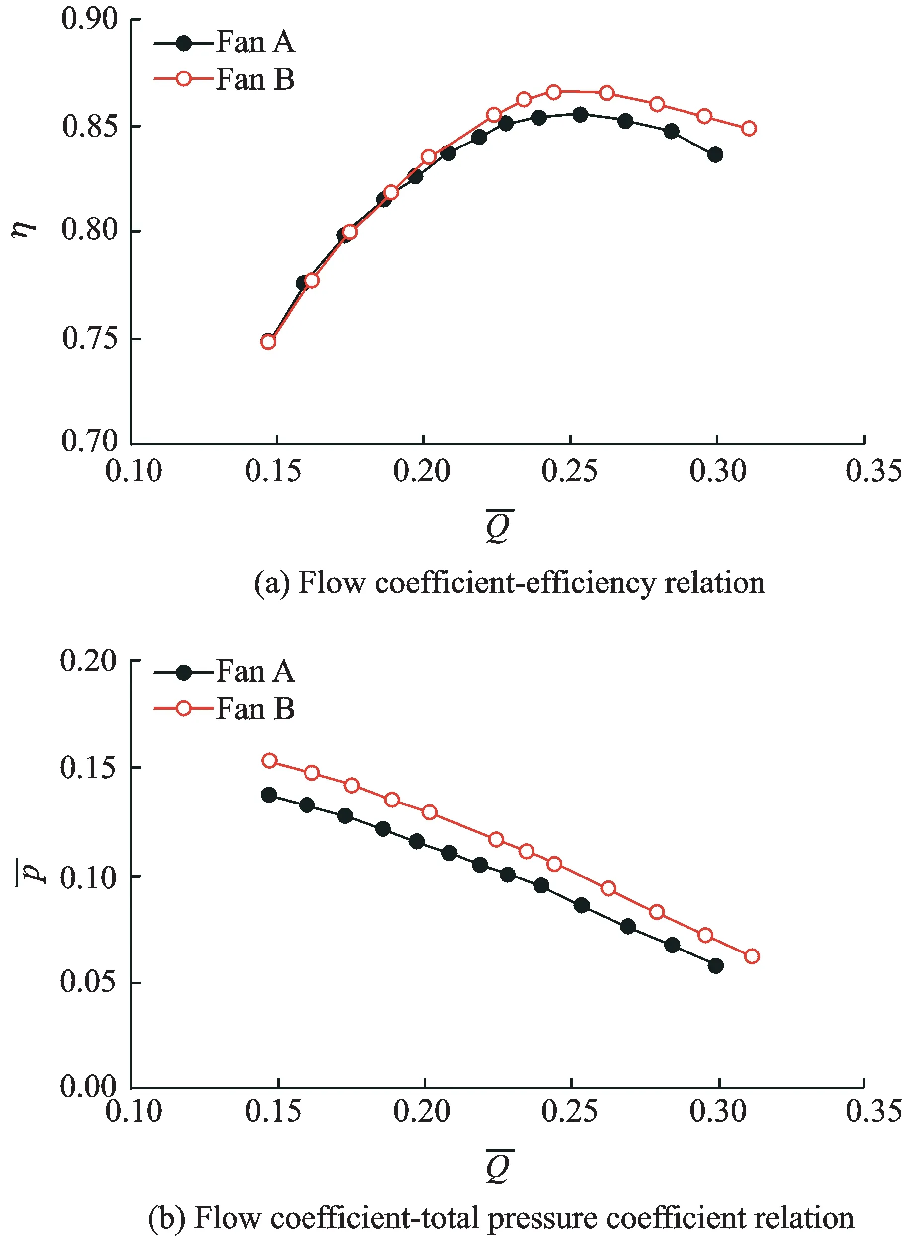
Fig.4 Fan dimensionless characteristics comparison
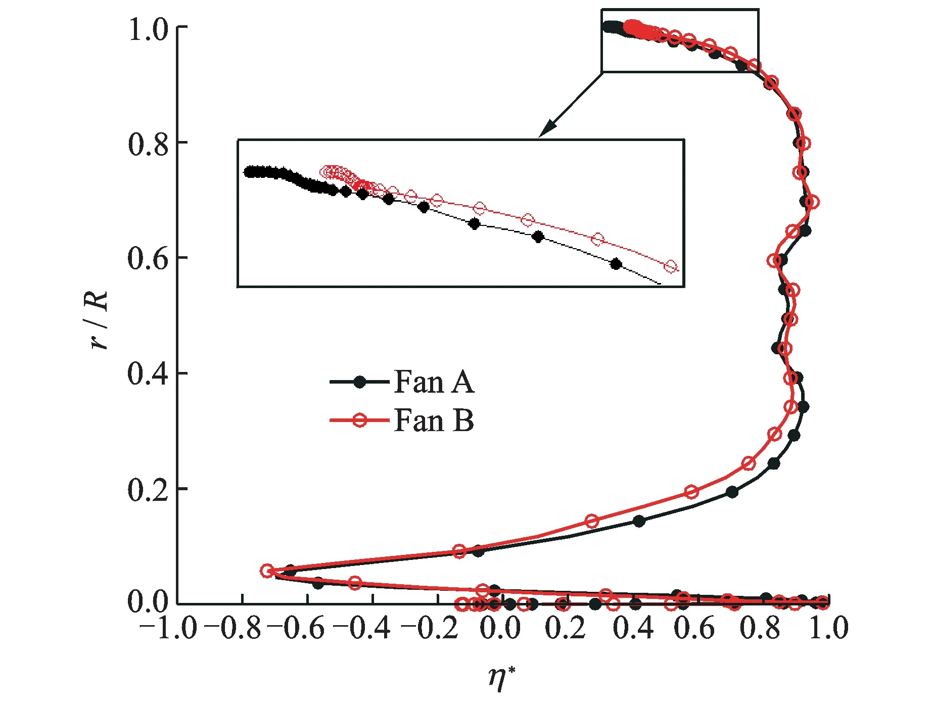
Fig.5 Radial distribution of isentropic efficiency at maximum efficiency point
3.2 Tip flow field comparison
Fig.5 shows the spanwise distributions of maximum isentropic efficiency of the two fans. The isentropic efficiency is defined as
(6)
Fig.5 shows that both isentropic efficiency curves show ″bow″ type distributions in the spanwise direction, wherer/Ris the relative blade height. In the region less than 15% blade height, the isentropic efficiency is below 0. As the flow speed is low here, the main consideration for this part of blade is the structural strength. The isentropic efficiency of the two fans has little difference between 35%—90% blade heights, while fan B shows a higher isentropic efficiency than fan A in more than 90% of the blade height including tip clearance. This indicates that tip-cutting can greatly influence tip flow field. As the tip rim speed is high, the flow in this region leaves a large proportion of entire-channel flow. The efficiency in this area has a great influence on the entire efficiency of the fan. Therefore, the whole area needs a thorough analysis.
Fig.6 shows the relative velocity streamlines in three tip clearance sections at maximum efficiency points of the two fans. The red, green, and blue lines represent the surface flow lines in the blade tip, 50% tip clearance and 90% tip clearance sections, respectively. The surface flow line is the projection of the relative velocity streamline on the surface. All the surface flow lines which start from the leading edge converge to one line after a short development. Each converged line reflects the leading edge of the tip leakage vortex in its surface.

Fig.6 Tip-leakage vortex and casing wall pressure distribution at maximum efficiency point
The tip leakage flow line starting at the leading edge of the blade reaches to adjacent blade tip clearance after a blade passage development, and a secondary leakage flow occurs in the tip clearance. This secondary leakage flow together with the local leakage flow forms a double-leakage flow. And the surface flow line in tip section reaches the exit of the adjacent blade. In contrast, the secondary leakage flow of fan B is closer to the local blade trailing edge than fan A (blue and green lines), and the surface flow line in blade tip section of fan B reaches the exit further away from the pressure side of the adjacent blade (red lines) without secondary leakage flow, indicating that the circumferential development of the tip leakage vortex in fan B is weakened to some extent compared to fan A; and that the flow capacity in tip region is improved after tip-cutting.
Fig.7 presents tip leakage vortex and entropy distribution at maximum efficiency point, whereSis the entropy. The tip leakage vortex is identified by the vortex core and the tip leakage streamlines from the leading edge. The vortex core is colored by the normalized helicityHn[11], which is defined as
(7)
whereζ,Wdenote vectors of the absolute vorticity and relative flow velocity, respectively.
The normalized helicityHncharacterizes the directional correlation of the absolute vorticity and relative flow velocity. The magnitude ofHntakes the value of unity anywhere the streamwise vortex is presented. It can assess the nature of vortex quantitatively, even when the vorticity decays. The sign ofHnrepresents the direction of swirl relative to the streamwise velocity component at the vortex axis. The point where the sign of it on the vortex core changes from negative to positive is the place where the tip-leakage vortex core is formed or broken. The pointAin Fig.7 is the starting position at which the tip leakage vortex is formed.Hnon the vortex core is almost +1 after the vortex is formed. Due to the presence of streamwise vortex, the vortex core is believed to represent the tip leakage vortex rolling up clockwise from the leading edge of the rotor tip. The difference between the two fans is that pointAin fan A is closer to the leading edge, which could induce a larger low-energy fluid region. One could see it from the entropy distribution in all planes.
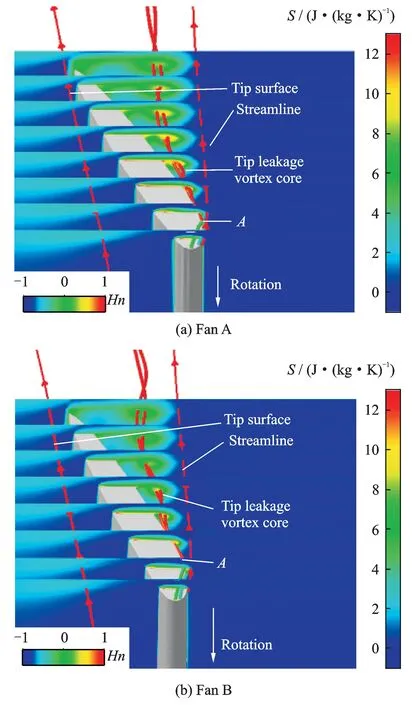
Fig.7 Tip-leakage vortex and entropy distribution at maximum efficiency point
From the entropy distribution map we can clearly see the leakage vortex occurs in the suction side of blade tip. The entropy production in the tip region of fan A is obviously greater than that of fan B. The greater entropy production is, the more energy losts. The tip leakage vortex spreads after pointA, which could greatly reduce the tip flow capacity.
In Fig.8, the distribution of static pressure coefficient at near-stall point is shown in casing and tip-leakage vortex paths from the leading edge.
The static pressure coefficient is defined
(8)
wherepsdenotes the static pressure and the subscript 1 the fan inlet ,ρthe air density andWthe relative velocity.
The minimum pressure is located near the leading edge on the suction surface, and the pressure trough in the two fans extends from the minimum pressure point to the adjacent blade import. Moreover, the tip leakage vortex extends to the adjacent blade import along the pressure trough. Both tip leakage vortices extend to the leading edge of the next blade and the spillage of tip leakage flow from the leading edge occurs. The tip leakage vortex in fan A reaches the rotor exit after 5 blade passages tangential development. In contrast, the development of tip leakage vortex in fan B just needs four blade passages. Moreover, the interaction between the tip leakage vortex and the wake in fan A generates a larger pressure loss at the rotor exit than that of fan B.
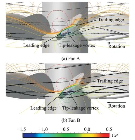
Fig.8 Tip-leakage vortex and casing wall pressure distribution at near-stall point
Fig.9 elaborates tip leakage vortex and entropy distributions at near-stall point of the two fans. The vortex core is also colored byHn. The influence range of tip leakage vortex is much larger than that at the maximum efficiency point both in the spanwise and pitchwise directions, comparing the entropy production areas in the tip region. The spillage of tip leakage flow from the leading edge is more clearly in three-dimensional quality. Nishioka et al.[12]indicated that the spillage of tip leakage flow from the leading edge could induce a larger total pressure loss than double leakage flow, and the pressure rise could be much lower in the tip region. The leakage vortex intensity of fan A is stronger than that of fan B, especially at the middle planes, which induces a larger low-energy fluid region and low flow capacity in the tip region.
4 Conclusions
The tip-cutting effect on performance of the large axial ventilation fan has been investigated using steady Reynolds-Averaged-Navier-Stokes (RANS) simulations. A geometry similar fan has been tested to verify the reliability of the numerical simulations. The results are summarized as follows:
(1) Cutting 6% blade can improve total pressure efficiency. And with the increase of flow efficient, the difference of efficiency between the two fans increases up to 1%. At the same time, 6% blade cutting has little effect on the fan′s stall margin. The fan with tip-cutting keeps almost the same flow coefficient and efficiency at near-stall point as the original one.
(2) The tip-leakage vortices at maximum efficiency point of the two fans have a vortex rolling up clockwise along the core flow direction. The double leakage flow just occurs in tip clearance, which has little influence on the entire performance.
(3) At the maximum efficiency point, the tip vortex of fan B passes further away from the pressure side of the adjacent blade than that of fan A, which improves the flow capacity in tip region. While at the near-stall point, the tip leakage vortex extends to the leading edge of the next blade, and the spillage of tip leakage flow from the leading edge occurs. The tip leakage vortex in fan A reaches rotor exit after five blade passages tangential development. In contrast, the development of tip leakage vortex in fan B just needs four blade passages to reach the rotor exit.
Acknowledgement
This work was supported by the Specialized Research Fund for the Doctoral Program of Higher Education (No.20113218120006).
[1] Zhong Jingjun, Han Shaobing, Lu Huawei. Numerical simulation of blade tip winglet on the aerodynamic performance of compressor cascade[J]. Journal of Engineering Thermophysics, 2010,31(2):243-246. (in Chinese)
[2] Shao Weiwei, Ji Lucheng, Huang Weiguang. Analysis of overall aerodynamic performance of axial-flow compressor with attenuated blade tip[J]. Journal of Aerospace Power, 2008,23(2):367-373. (in Chinese)
[3] Yuan Wei, Zhou Sheng, Lu Yajun. 3D numerical analysis for the effect between tip clearance and casing treatment in turbomachinery[J]. Journal of Beijing University of Aeronautics and Astronautics, 2004,30(9):885-888. (in Chinese)
[4] Lakshminarayani B, Sitaram N, Zhang J. End-wall and profile losses in a low-speed axial flow compressor rotor[J]. ASME J Engineering for Gas Turbine and Power, 1986, 108:22-31.
[5] Inoue M, Kuroumaru M, Fukuhara M. Behavior of tip leakage flow behind an axial compressor rotor[J]. ASME J Engineering for Gas Turbine and Power, 1986, 108:7-14.
[6] Qiu Ming, Zhou Zhenggui. Application of numerical optimization method in aerodynamic design of axial compressor rotor[J]. Journal of Nanjing University of Aeronautics & Astronautics, 2013,45(1):75-81. (in Chinese)
[7] Wang Jun, Yao Ruifeng, Liu Jing, et al. Influence of tip clearance on external performance and tip leakage vortex of low-pressure axial fan[J]. Fluid Machinery, 2011,39(9):26-30. (in Chinese)
[8] Zhu Xiaocheng, Lin Wanlai, Du Zhaohui. Experimental study on the tip leakage flow of an axial fan[J]. Journal of Shanghai Jiaotong University, 2005,39(2):177-181.
[9] Lü Feng, Zhao Yanjie, Li Jingyin. Effects of blade cutting on the performance of large-type axial-flow fan[J]. Compressor Blower and Fan Technology, 2012(2):18-22.
[10]Zhang Yucheng, Yi Dengli, Feng Dianyi, et al. Ventilator design and selection[M]. Beijing: Chemical Industry Press, 2011. (in Chinese)
[11]Yamada K, Funazaki K, Furukawa M. The behavior of tip clearance flow at near-stall condition in a transonic axial compressor rotor[C]∥Proceedings of the ASME Turbo Expo 2007-Power for Land, Sea, and Air. USA: ASME, 2007:295-306.
[12]Nishioka T, Joko M. Characteristic of tip-leakage flow at high stagger-angle setting for rotor blade in an axial flow[R]. GT2012-6920, ASME, 2012.
(Executive Editor: Zhang Bei)
V211.3 Document code:A Article ID:1005-1120(2015)06-0623-08
*Corresponding author: Hu Jun, Professor, E-mail:hjape@nuaa.edu.cn.
How to cite this article: Yin Chao, Hu Jun, Yan Wei, et al. Effect of tip-blade cutting on the performance of large scale axial fan[J]. Trans. Nanjing U. Aero. Astro., 2015,32(6):623-630. http://dx.doi.org/10.16356/j.1005-1120.2015.06.623
 Transactions of Nanjing University of Aeronautics and Astronautics2015年6期
- Transactions of Nanjing University of Aeronautics and Astronautics的其它文章
- Unicast Network Topology Inference Algorithm Based on Hierarchical Clustering
- Structure Design of Shaped Charge for Requirements of Concrete Crater Diameter
- Fault Detection Based on Incremental Locally Linear Embedding for Satellite TX-I
- Deformation Analysis on Shear-Bending of Ring-Shaped Piezoelectric Actuator
- Mechanical Behavior of Bistable Bump Surface for Morphing Inlet
- Infrared Heating Technology for Automated Fiber Placement