
Novel scheme of high precision inertial measurement for high-speed rotating carriers
2015-04-22 06:17WUQingya武庆雅JIAQingzhong贾庆忠SHANJiayuan单家元MENGXiuyun孟秀云
WU Qing-ya(武庆雅), JIA Qing-zhong(贾庆忠), SHAN Jia-yuan(单家元),MENG Xiu-yun(孟秀云)
(Key Laboratory of Dynamic and Control of Flight Vehicle, Ministry of Education, School of Aerospace Engineering,Beijing Institute of Technology, Beijing 100081,China)
Novel scheme of high precision inertial measurement for high-speed rotating carriers
WU Qing-ya(武庆雅), JIA Qing-zhong(贾庆忠), SHAN Jia-yuan(单家元),MENG Xiu-yun(孟秀云)
(Key Laboratory of Dynamic and Control of Flight Vehicle, Ministry of Education, School of Aerospace Engineering,Beijing Institute of Technology, Beijing 100081,China)
In order to satisfy the requirement of high precision measurement in a high dynamic environment, a kind of gyro aided multi-accelerometer inertial measurement unit (GAMA-IMU) with six accelerometers and two gyros (6A2G) was proposed in this paper. The available configurations have the problem of low measurement precision in a high dynamic environment due to channel coupling. The three channels were decoupled when calculating the angular velocity in the proposed configuration. The yawing and pitching angular velocity were directly measured by gyros, while only the rolling angular velocity was obtained by the GAMA-IMU indirectly from the rolling angular acceleration and quadratic component of rolling angular velocity. Then a single channel rolling angular velocity calculation model was established and the extended Kalman filter (EKF) was used to do state estimation. Simulations were carried out and results indicated that the calculation precision of the proposed 6A2G configuration could meet the demand of high precision measurement for a high-speed rotating carrier.
high-speed rotating carrier; gyro aided multi-accelerometer; angular velocity calculation; extended kalman filter (EKF)
A spinning carrier refers to a carrier rotating around its own lengthwise axis when flying. A carrier’s spin may bring many advantages[1]. On the other hand, it can also induce a series of problems, among which, high precision measurement of large rolling angular velocity is an important one. When the rolling angular velocity is too large for the gyro to measure directly, accelerometers are used instead to accomplish this task, which benefits from the lever-arm effect. The angular velocity calculation precision of this method mainly depends on the configuration of the inertial measurement unit (IMU), including gyro-free IMU (GF-IMU)[2-14]and gyro aided multi-accelerometer IMU (GAMA-IMU)[15-16].
The most classic GF-IMU configurations are six-accelerometer (6A) cubic configuration[2], nine-accelerometer (9A) configuration[3-6]and twelve-accelerometer (12A) configuration[7-14]. Among these three configurations, the 6A configuration has low angular velocity calculation precision for error accumulation. The angular velocity calculation precision of the 9A configuration would decrease as the rolling angular rate getting higher due to the channel coupling, indicating that this configuration is not suitable for high-speed rotating carrier. So many accelerometers are used in the 12A configuration that it would result in high system costs, decreased system reliability and increased installation difficulty. Clearly, all the three classical configurations are not suitable for engineering application. As for the GAMA-IMU configuration, Wang Lei et al[15]proposed a four-accelerometer two-gyro (4A2G) configuration, which used few instruments but could not ensure the sign of the rolling angular rate. Mu Shuzhi et al[16]adopted seven, five and four accelerometers respectively to go with a two-axis gyro to form three different kinds of GAMA-IMU. The rolling angular rates were all calculated by mathematic analysis method, among which the division operation might induce gross error data. Besides, the GAMA-IMU with five and four accelerometers both could not insure the sign of the rolling angular rate.
Aiming at the aforementioned problems, a GAMA-IMU with six accelerometers and two gyros (6A2G) were proposed in this paper. The yawing and pitching angular velocities were measured directly by gyros, while the angular information produced by the GAMA-IMU indirectly only concerns rolling angular velocity for channel decoupling. Then, the single channel state space model was established and the extended Kalman filter (EKF) algorithm was used to estimate the rolling angular velocity due to the nonlinear measurement equation. Simulation results indicated that the proposed configuration could be used on a carrier rotating at any high speed.
1 Novel GAMA-IMU configuration
The GAMA-IMU configuration proposed in this paper consists of six accelerometers and two gyros and all the sensors are fixed on bracket coincident with the body fixed coordinate system, as shown in Fig. 1. The body fixed coordinate system is defined to have the origin at the center of gravity with thex-axis pointed out the nose, and they- andz-axes pointing to the “up” and “right” respectively, when viewed from the rear.
Gyros G1, G2 and accelerometers F1, F2 and F5 are installed at the origin of the carrier. G1 and G2 sense the angular velocities ony- andz-axes, the outputs of which are denoted asg1andg2respectively. For calculation convenience and without loss of generality, the other three accelerometers are of the same distance from the origin, denoted asd.
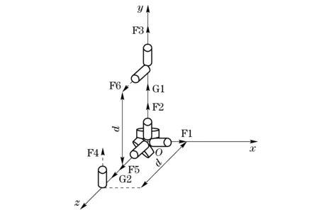
Fig.1 6A2G IMU configuration
The output of the accelerometer fixed at non-centroid of the body is the summation of the specific force at the center of mass and the acceleration induced by rotation. Let r denotes the installation position vector of the accelerometer andθdenotes its sensitive orientation vector, then the output of the accelerometer located at any position can be expressed as follows:

(1)

For the proposed 6A2G configuration, the installation position matrix of the accelerometer is
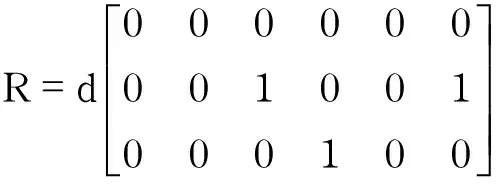
(2)
The sensitive direction matrix is
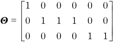
(3)
Letfi,i=1,…,6 denote the outputs of the six accelerometers respectively. According to Eqs.(1)-(3), information concerning the angular velocity can be obtained:
(4)
(5)
(6)
ωy=g1
(7)
ωz=g2
(8)
Substitute Eq. (8) into Eq. (5),we have
(9)
Intuitively,ωycan be obtained by dividing Eq.(6) by Eq.(8), which induces an illusion that gyro G1 is useless. Practically,ωzis so small that gross error datum would easily be created if it is the denominator in a division operation. Hence gyro G1 is essential for ensuring the measurement precision ofωy. Besides,f1is unused in Eqs.(4)-(8), but the accelerometer F1 is not redundant for it is used to measure linear acceleration ofx-axis.
2 Rolling angular velocity calculation based on EKF
ωyandωzcan be output directly by gyros, so we can get the complete angular velocity information ifωxis acquired. Based on Eqs.(4) (9), the two basic angular velocity calculation methods can be obtained, that is, the integration method and the evolution method. The way of integrating Eq.(4) directly to getωxis called the integration method. First getting its absolute value through taking the square root of Eq.(9), and then judging its sign according to the value calculated by the integration method is considered as the evolution method. The integration method will easily result in error accumulation, and the evolution method will induce misjudgement of the sign due to the inaccurate data calculated by the integration method, which are the reasons why a more extraordinary approach is needed to calculate the rolling angular velocity.
The channels have been decoupled benefits from the proposed GAMA-IMU configuration when calculating the angular velocities, thus a single channel rolling angular velocity calculation model was established and filter theory was brought in to do state estimation. In fact, handling the problem in this way will not only simplify the system model, but also offer a chance for the 6A2G IMU to be applied on a high-speed rotating carrier.
We firstly establish the single channel rolling angular velocity calculation state space model. Suppose the static error, dynamic error and installation error of the accelerometers and gyros have been calibrated and compensated. Only the random error is considered in this paper. Suppose the random error is Gaussian white noise with zero mean. The random errors of the six accelerometers are denoted as Δfi,i=1,…,6 respectively and that of gyro G2 is denoted as Δg2.
Let the sampling interval beT, and the following equation can be obtained:
(10)
wherethesubscriptkdenotes the variable at timestepk. Consider the rolling angular acceleration calculated through Eq.(4) as input, denoted asu, and then we get
Δf4,k-1-Δf5,k-1)
(11)
Substitute Eq.(11) into Eq. (10):
Δf5,k-1-Δf2,k-1-Δf6,k-1)
Considerx=ωxas state, and the state equation is
xk=Φxk-1+Ψuk-1+Γwk-1
(12a)
whereΦ=1,Ψ=T,Γ=T/(2d),wk-1=Δf4,k-1+Δf5,k-1-Δf2,k-1-Δf6,k-1. The statistical characteristics ofwk-1are
LetDi,i=2,…,6 denote the variance offi,i=2,…,6 respectively, andQk-1=D2+D3+D4+D6.
Set the quadratic component of the rolling angular velocity calculated through Eq.(9) as observations and letfthrydenote the specific force without error, then we can get

zk=h(xk)+vk
(12b)
whereRk=(D2+D3)/d2.
We can see that the state equation is linear while the measurement equation is nonlinear. Due to the nonlinear measurement equation, the standard KF algorithm is no longer suitable for this situation and a nonlinear filtering approach is needed instead.
EKF and unscented Kalman filter (UKF) are the two nonlinear filter algorithms most wildly used. Many researchers have proved that the two algorithms performs equally when the system model has little nonlinearity[17-18]. However, compared to UKF, EKF has much higher calculation efficiency, which makes it more suitable to solve the problem in this paper. Rolling angular velocity estimation steps based on EKF are as follows[19]:
① Initialization:
The initial state and initial estimation error covariance can be set as
②Prediction:
Theprioristateestimateandprioriestimationerrorcovarianceareupdatedas
Pxx,k|k-1=ΦPk-1ΦT+ΓQk-1ΓT=Pk-1+T2Qk-1/4d2
③ Measurement update:
The Jacobian of the measurement model is expressed as
TheKalmangainisupdatedas
Theposterioristateestimateandposterioriestimationerrorcovarianceareupdatedas
Pk=(I-KkHk|k-1)Pxx,k|k-1
3 Simulations and results analysis
Simulations were carried out in three aspects. Firstly the performance on rolling angular velocity estimation of the 6A2G configuration was tested; then the necessity of gyro G1 was verified; lastly the proposed 6A2G configuration was contrasted with the 9A configuration to further validate its good performance on angular velocity calculation.
Suppose the carrier’s rotational speed is 10 r/s. The sampling interval is chosen to be 1 ms and the flight time is set as 300 s. Consider different kinds of flight conditions during flight, such as climbing, flat flight, swerve and dive, and consider effect of earth rotation. Fig.2 shows a plot of the angular velocity profile.
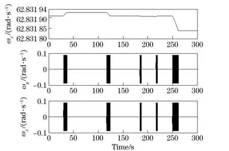
Fig.2 Angular velocity profile
The shadow areas ofωyandωzin Fig.2 represent oscillation with a frequency ofωx/2π. Angular motion in one direction will trigger that with the same amplitude and frequency in the other on account of the carrier’s rotation.
Suppose the random error of the accelerometer is 5×10⁻⁵gand the random error of the gyro is 10(°)/h. The contrast error curves when adopting the filter approach, the evolution approach and the integration approach to estimate the rolling angular velocity are shown in Fig.3.
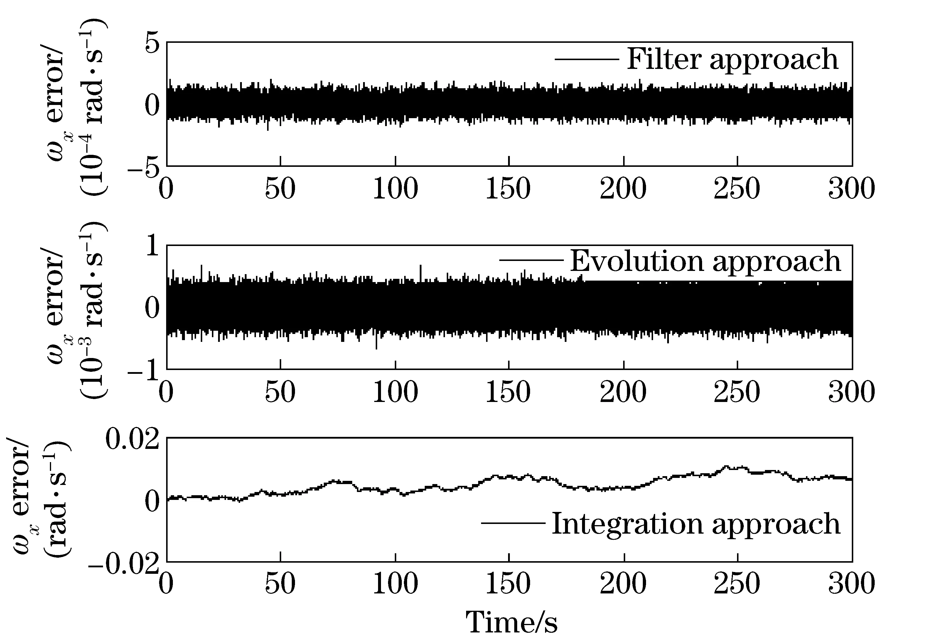
Fig.3 Angular velocity error of x-axis based on the three approaches
Meanwhile, the standard deviations of the estimated errors of each angular velocity calculation approach are 4.611 2×10⁻⁵, 1.378 6×10⁻⁴and 2.737 3×10⁻³respectively. The results indicate that the integration method is not proficient in calculating the angular velocity, for it would induce error accumulation. The filter approach and evolution approach can both effectively estimate the angular velocity and keep the errors within small range without accumulation. The evolution method relies on the integration method to judge the sign, which may induce misjudgement as error accumulating. The reason why there is no gross error data produced by the evolution method is that the rotation speed is set to be relatively high, and the cumulate errors may count for nothing in mistaking the sign of the angular velocity calculated by the integration method. Even so, the precision of the evolution method is inferior to that of the filter method, whose performance has been as good as a gyro.
In order to verify the necessity of gyro G1 in the proposed 6A2G configuration, the calculation error ofωygenerated from division computation was plotted in Fig. 4. It can be seen that the gross error data are large, indicating that the division method is not an advisable choice.ωyshould be measured by gyro G1 to ensure the accuracy.
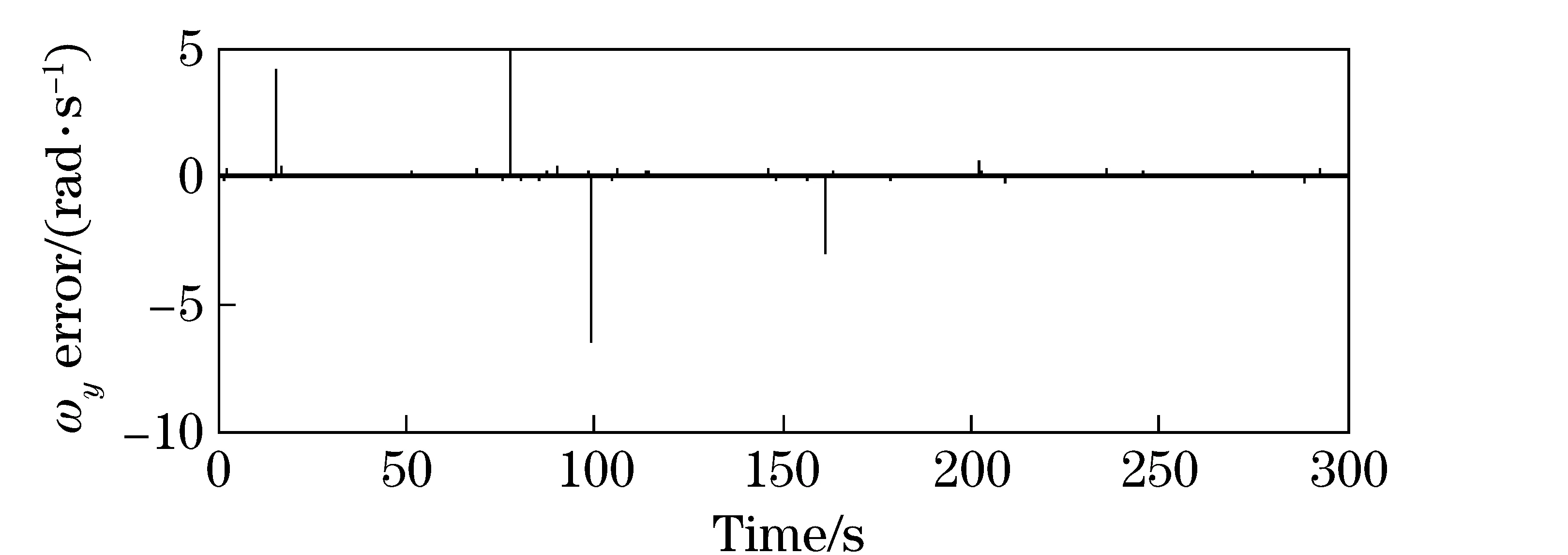
Fig.4 Angular velocity error of y-axis based on division
In the precondition that the sampling interval remains unchanged, the rolling angular velocity calculation precision of the available configurations may decrease as the rotation speed increases owing to channel coupling. However, the 6A2G configuration proposed in this paper can achieve the effect that the calculation precision of rolling angular velocity increases as the rotation speed increases under a certain sampling interval. In order to verify the superiority of the proposed 6A2G configuration, comparison experiments were carried out between this configuration and the classical 9A configuration[6]. Three-channel angular velocity calculation modal of the 9A configuration is established in the same approach as that described in Section 2. The standard deviations of the estimated errors based on the filter approach under different rotation speeds of the two configurations are listed in Tab.1.
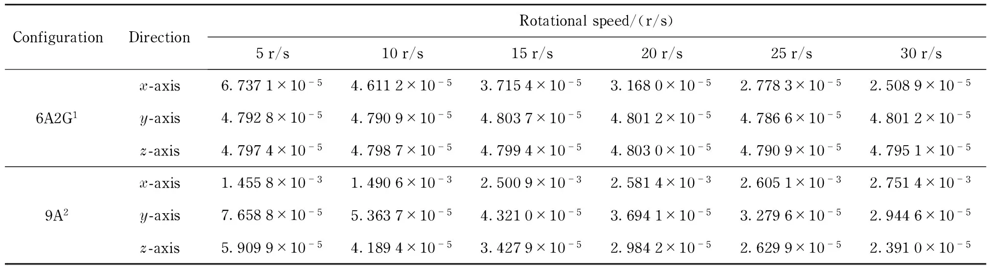
Tab.1 Standard deviation of angular velocity estimated error based on 6A2G and 9A configuration
1—six-accelerometer two-gyro configuration; 2—nine-accelerometer configuration
It can be seen that the proposed 6A2G configuration behaves well on all the three channels. The measurement precision of yawing and pitching angular velocity barely changes for they are directly output by gyros. More than anything, the estimated error of rolling angular velocity decreases as the rotation speed increases, leading to a benefit that the configuration can be used on carrier rotating at any speed. The performance of 9A configuration is close to that of 6A2G configuration on the yawing and pitching channels, but the errors of rolling channel are much larger, and will grow larger with the increasing of rotation speed. Although the precision of yawing and pitching channel of the 9A configuration will increase a little bit as the rotation speed increases, it can’t fill the gap of low calculation precision of rolling angular velocity.
贸易互补性指数。主要是衡量两国间贸易互补程度,通常以一国特定产品出口的比较优势与其贸易伙伴国该产品进口的比较劣势的乘积来衡量。计算公式如下:
4 Conclusions
In this paper, a 6A2G IMU configuration is proposed to measure the angular velocity with high precision for a high-speed rotating carrier. The configuration has the three channels decoupled when calculating the angular velocity to solve the low calculation precision problem due to channel coupling. Based on it, a single channel state space model is established and the EKF algorithm is utilized to estimate the rolling angular velocity. Simulation results show that the proposed scheme can provide high precision measurement for a carrier rotating at high speed.
The future work is to derive a whole set of navigation algorithms perfectly suitable for GFSINS (NGFSINS) to finally obtain the attitude, speed and location of the carrier, and the integrated navigation system should also be developed to improve navigation precision.
[1] Li Xingcheng, Zhang Shuangbiao. Stability study of spiral motion based on calculated flight data[J]. Transactions of Beijing Institute of Technology, 2012, 32(12): 1223-1228.(in Chinese)
[2] Jeng Heng Chen, Lee S C, Daniel B DeBra. Gyroscope free strap-down inertial measurement unit by six linear accelerometers[J]. Journal of Guidance, Control and Dynamics, 1994, 17(3): 286-290.
[3] Wang Jinsong, Wang Qi, Sun Shenghe. Optimal technology for non-gyro micro inertial measuring unit[J]. Journal of Harbin Institute of Technology, 2002, 34(5): 632-635.(in Chinese)
[4] Park S, Tan C W, Park J. A scheme for improving the performance of a gyroscope-free inertial measurement unit[J]. Sensors and Actuators A: Physical, 2005, 121: 410-420.
[5] Chen T L, Park S. MEMS SoC: observer-based coplanar gyro-free inertial measurement unit[J]. Journal of Micromechanics and Microengineering, 2005, 15: 1664-1673.
[7] Zhang Huixin, Wang Shichang, Yang Yunliang, et al. Method optimization for angular velocity calculating in inertial testing system composed with full accelerometers[J]. Journal of Chinese Inertial Technology, 2008, 16(6): 672-675.(in Chinese)
[8] Buhmann A, Peters C, Cornils M, et al. A GPS aided full linear accelerometer based gyroscope-free navigation system[C]∥Proceedings of IEEE/ION PLANS 2006, San Diego, CA, 2006:622-629.
[9] Parsa K, Lasky T A, Ravani B. Design and implementation of a mechatronic, all-accelerometer inertial measurement unit[J]. IEEE/ASME Transactions on Mechatronics, 2007, 12(6): 640-650.
[10] Schopp P, Klingbeil L, Peters C, et al. Sensor fusion algorithm and calibration for a gyroscope-free IMU[J]. Procedia Chemistry, 2009, 1: 1323-1326.
[11] Park S, Hong S K. Angular rate estimation using a distributed set of accelerometers[J]. Sensors, 2011, 11: 10444-10457
[12] Cappa P, Patane F, Rossi S. Two calibration procedures for a gyroscope-free inertial measurement system based on a double-pendulum apparatus[J]. Measurement Science and Technology, 2008, 19: 1-9.
[13] Edwan E, Knedlik S, Loffeld O. Constrained angular motion estimation in a gyro-free IMU[J]. IEEE Transactions on Aerospace and Electronic Systems, 2011, 47(1): 596-610.
[14] Cardou P, Fournier G, Gagnon P. A nonlinear program for angular-velocity estimation from centripetal-acceleration measurements[J]. IEEE/ASME Transactions on Mechatronics, 2011, 16(5): 932-944.
[15] Wang Lei, Hao Yongping, Xiao Chang, et al. The simulation and experiment research of inertial navigation system used for shell in high dynamic environment[J]. Journal of Projectiles, Rockets, Missiles and Guidance, 2009, 29(2): 4-8.(in Chinese)
[16] Mu Shuzhi, Bu Xiongzhu, Li Yongxin, et al. Research on inertial measurement unit of high rotation vehicle[J]. Journal of Ballistics, 2006, 18(4): 85-88.(in Chinese)
[17] Matthew Rhudy, Yu Gu, Jason Gross, et al. Sensitivity analysis of EKF and UKF in GPS/INS sensor fusion[C]∥AIAA Guidance, Navigation, and Control Conference, Portland, Oregon, 2011: 1-15.
[18] Zhao Sihao, Lu Mingquan, Feng Zhenming. Application of EKF and UKF in tightly-coupled integrated navigation system[J]. Systems Engineering and Electronics, 2009, 31(10): 2450-2454.(in Chinese)
[19] Fu Mengyin, Deng Zhihong, Yan Liping. Kalman filtering theory and its application in the navigation system [M]. 2rd ed. Beijing: Science Press, 2010:160-171.(in Chinese)
(Edited by Wang Yuxia)
10.15918/j.jbit1004- 0579.201524.0202
V 249.322Document code: A Article ID: 1004- 0579(2015)02- 0151- 07
Received 2013- 08- 23
E-mail: bitjqzh96@163.com
猜你喜欢
金桥(2022年8期)2022-08-24
哈尔滨工业大学学报(社会科学版)(2020年1期)2020-01-09
世界热带农业信息(2019年3期)2019-06-20
-- Китай" --" --верный шагк углублению энергетического сотрудничества
中亚信息(2016年8期)2016-12-06
新闻传播(2016年9期)2016-09-26
出版与印刷(2016年1期)2016-01-03
出版与印刷(2015年4期)2015-01-03
外语学刊(2011年3期)2011-01-22
 Journal of Beijing Institute of Technology2015年2期
- Journal of Beijing Institute of Technology的其它文章
- Nonlinear symbolic LFT model for UAV
- Study on influencing factors of adapters separating with the underwater missile
- Fast-solving method for air-to-surface guided bombs’ allowable attack area
- Design and analysis of mechanical self-destruction and self-neutralization mechanism for submunition fuze
- Resilience approach for heterogeneous distributed networked unmanned weapon systems
- Modeling and simulation of the static characteristics of diaphragm spring clutches