Multi-position alignment with arbitrary rotation axis for SINS
2015-05-23 03:53TANCaimingZHUXinhuaWANGYuSUYan
中国惯性技术学报 2015年3期
TAN Cai-ming, ZHU Xin-hua, WANG Yu, SU Yan
(School of Mechanical Engineering, Nanjing University of Science and Technology, Nanjing 210094, China)
Multi-position alignment with arbitrary rotation axis for SINS
TAN Cai-ming, ZHU Xin-hua, WANG Yu, SU Yan
(School of Mechanical Engineering, Nanjing University of Science and Technology, Nanjing 210094, China)
The multi-position alignment method based on single-axis rotation strapdown inertial navigation systems (SINSs) usually requires the rotation axis to be along the azimuth axis, and the coincidence error of the axes could influence the accuracy of the multi-position method. To solve this problem, a multi-position initial alignment method was proposed, in which the rotation axis could be in arbitrary direction without having to coincide with the azimuth axis. The whole biases of the IMU could be obtained only by making the IMU rotate over two given angles. In this way, the performance of the alignment is improved. Simulation results show that the alignment accuracy of the proposed multi-position method is significantly improved compared with that of the one-position analytic coarse alignment method, and the error of the yaw is decreased to less than 0.2′ from the original 5′.
multi-position alignment; single-axis rotation; initial alignment; SINS
Alignment is the first step for inertial navigation, and the precision of the alignment directly affects the performance of the inertial navigation[1].
To improve the self-alignment performance, the error of the inertial measurement unit (IMU) should be compensated. The biases of the IMU are not completely observable when the IMU remains static without any additional information[2-3]. Without using additional sensors, there are two techniques, namely, continuous rotation and multi-position, that can help increase the observability[4-7].
There are currently two-position, three-position, and four-position alignment methods for the multi-position alignment method. We find that the rotation axis is usually along the body axis[6-8]. The multi-position methods based on single-axis rotation SINS usually require the rotation axis to be along the azimuth axis, and the error of the axis coincidence affects the accuracy of the multi-position alignment method. Furthermore, making the rotation axis of the rotation device coincide with the IMU body axis increases the cost of production. We propose a multi-position alignment where the rotation axis can be arbitrary.
1 Principle
1.1Multi-position analysis for three-axis accelerometers or gyroscopes
As shown in Fig.1, the rotation axis is.is the direction of Earth’s gravity or Earth’s rotation, for the three-axis accelerometers or the three-axis gyroscopes, respectively. AB is one of the body axes, assume to be the xb-axis. AB is rotated about AO counterclockwise. Let ∠POB=γ, ∠OAB=α,∠OAM=β, AB=k, and then derive cos∠MAB.

Fig.1 Geometrical analysis of the multi-position alignment method for three-axis accelerometers or gyroscopes
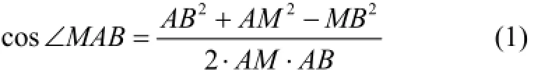
According to the cosine law in AMBΔ, we have:
It is easy to obtain:

With AB, AM and MB obtained, according to (1), cosMAB∠ is given by:

If α=90°, the rotation axis is along the yb-axis or zb-axis, or the rotation axis is parallel to the plane of the O-ybzb. If β=0, the rotation axis is along the direction of Earth’s gravity or Earth’s rotation.
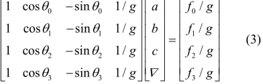
The rotation angle is θi. Let AM be along the direction of Earth’s gravity. Assume IMU is rotated several times, and the rotation angles are marked as θi, i=1,2... . The corresponding outputs for the accelerometer are marked as fi. With only bias being considered, the bias is seen as a constant denoted by ∇ because the alignment process is short. We have: where β, α, γ, and ∇ are unknown, θiand fiare given, and g denotes the gravitational force. Let θ0=0 as the initial position. Assume four positions are used.

Let a=cosβcosα , b=sinβsinαcos γ, and c=sinβsinαsin γ, then we have:
Equation (3) is marked as =AXB. Because rank()34=<A, there are either no or infinite solutions for X in (3). Because (:,1)A and (:,4)A are always linear correlations, and rank()3=A, there are either no or infinite solutions for X in (3), regardless of how many positions are used.
Similarly, for the three-axis gyroscope, we have:

As shown in Fig.2, AM is along the direction of Earth’s gravity, AN is along the direction of Earth’s rotation. Based on the analysis of the three-axis accelerometers or the three-axis gyroscopes, we have:
whereiew denotes the rotation rate of the Earth, ε is the bias of the gyroscope, andiw denotes the output of the gyroscope in the axis we consider at the ithposition.
1.2Multi-position analysis for IMU
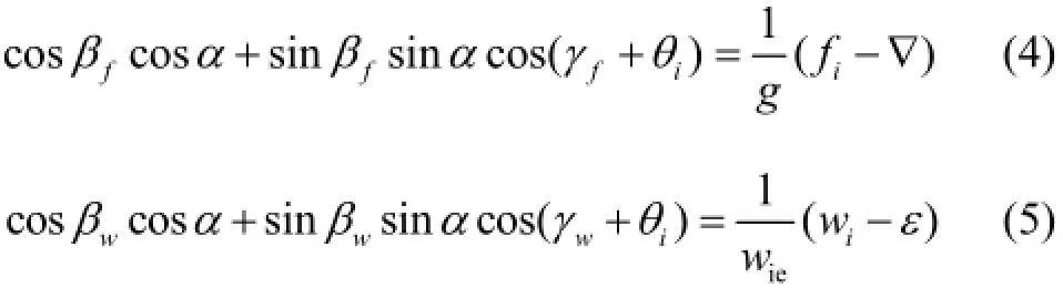
where γfand γwdenote the ∠POB for the accelerometer and gyroscope, respectively, as shown in Fig.1. βf=∠OAB , βw=∠OAN , as shown in Fig.2.
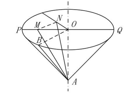
Fig.2 Geometrical analysis of the multi-position alignment method for IMU
Let OAl=, then we can obtain:
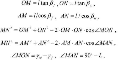
where L is the latitude. The following equation can be obtained according to the above equations.

where βf, βw, γf, γw, α, ∇, and ε are unknown. There are 7 unknowns in all. Three positions are used. Let θ0=0, θ1=90° and θ2=180° for ease of computation. We have:
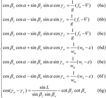
Adding (6a) and (6c) yields:

Substituting (7) into (6c) yields:

Substituting (7) into (6b) yields:

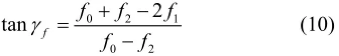
Dividing (9) by (8) yields:
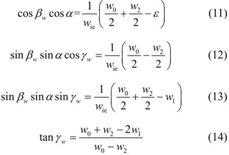
In the same way, according to (6d), (6e), and (6f), we obtain:
According to (9), we have:
According to (13), we have:

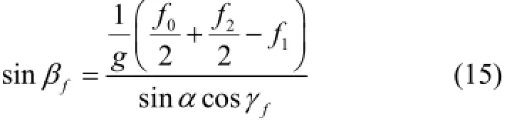
f
γ andwγ can be obtained according to (10) and (14), respectively. Substitute (15) and (16) into (6g), α can be obtained. Then, ∇ and ε can be computed according to (7) and (11).
1.3Computation procedure
We now consider the detailed procedure to calculate∇ and ε. According to (10) and (14), γfand γwcan be obtained. Because 0≤γf, γw≤2π, there can be two solutions for γfor γw. According to (10), we have:
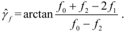
The result of ˆfγ is within. Due to the range offγ, we have:
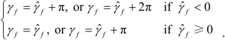
Similarly, according to (14), we have:

The result of ˆwγ is within. Due to the range ofwγ, we have:
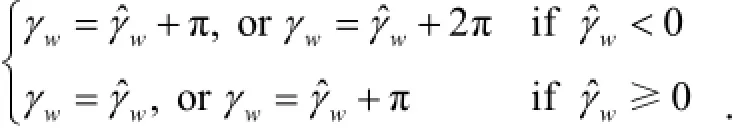
According to (15), (16) and (6g), the different sets of solutions offγ andwγ reach the same result for α,so we can take the following forfγ andwγ to compute α.

According to (6g), we have:

Taking the square of both sides yields:
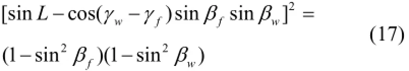
Substituting (15) and (16) into (17) yields:
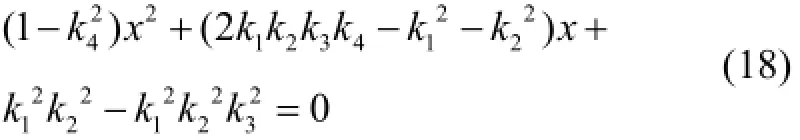
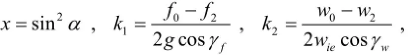
where k3=cos(γw-γf), and k4=sinL.
Because 0≤α≤π, there can be four solutions for α according to (18). Substituting α into (15) and (16) yields the solutions for βfand βw, respectively. Given βf, βwand α, we can obtain ∇ and ε according to (7) and (11). Although several sets of solutions for ∇ and ε can be obtained, we know that the values of ∇ and ε can never be imaginary and they must be within a small range, so it is easy to pick the right ones.
2 Simulations
Simulations were conducted to test the proposed multi-position alignment method.
A local ENU (East-North-Up) frame is used as the navigation frame, denoted by O-xnynzn. The body frame of the IMU is denoted by O-xbybzb. The platform frame is denoted by O-xpypzp. The rotation axis coincides with the zp-axis, as shown in Fig.3. The attitude of the IMU with respect to the platform remains unchanged.
The attitude angles of the platform with respect to the navigation frame are
= [5°, 5°, 30°]Tat first, where,anddenote the roll angle, pitch angle and yaw angle of the platform, respectively, with respect to the navigation frame. Let[3°, 3°, 3°]T. The platform stays in the first position for one minute. Then, the platform rotates about the zp-axis by 90°. This position is maintained for one minute. The platform then rotates about the zp-axis by 90° and is maintained at the third position for one minute.

Fig.3 IMU-body frame and platform frame
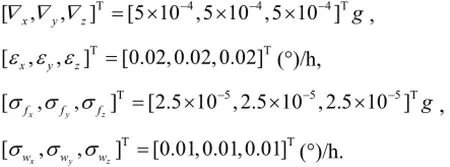
Because the alignment is usually performed in a short period of time, the constant bias and white noise in the SINS were considered. The values of the various parameters were chosen as follows: where ∇iis the constant bias for the i-axis accelerometer, εiis the constant drift for the i-axis gyroscope,is the standard deviation of the white noise for the i-axis accelerometer, and σwiis the standard deviation of the white noise for the i-axis gyroscope. The sampling rate was 100 Hz. We sampled the IMU outputs at the three positions. The average values of the outputs at each position were computed and used to test the proposed multi-position alignment method. The latitude was assumed to be 32.026372°N. The constant biases of the three-axis accelerometer and the constant drifts of the three-axis gyroscope can be obtained using the proposed method explained in Section 1. Given the biases and drifts, the sensor errors of the IMU are greatly reduced, and the performance of the alignment results from (19) are improved.

The multi-position alignment method was compared with the analytic coarse alignment using the data in the third position only. The same simulation experiment was conducted 50 times. The alignment results are shown in Fig.4. From Fig.4, we can observe that the alignment performance using the proposed multi-position alignment method is greatly improved. The yaw error is reduced from approximately 5′ to less than 0.2′.

Fig.4 Alignment results for the multi-position alignment method and the one-position analytic coarse alignment method
3 Conclusion
We propose a multi-position alignment method for single-axis rotation SINS. The IMU needs to be rotated about one axis, which could be an arbitrary axis, whereas the multi-position alignments for single-axis rotation SINS proposed previously usually require the rotation axis to be along the azimuth axis. Without knowing the rotation axis, three positions are required to obtain all of the biases, which are 0°, 90°, and 180° for the convenience of the computation. We derive the equations through a geometrical method. The simulations prove the validity of this multi-position alignment method. The alignment performance is greatly improved compared with that of the one-position analytic coarse alignment.
[1] Titterton D, Weston J L. Strapdown inertial navigation technology[M]. 2nd ed. Stevenage, UK: The Institution of Electrical Engineers, 2004.
[2] Cho S Y, Lee H K. Observability and estimation error analysis of the initial fine alignment filter for nonleveling strapdown inertial navigation system[J]. Journal of Dynamic Systems, Measurement, and Control, 2013, 135(2): 021005.
[3] Wang X L. Fast alignment and calibration algorithms for inertial navigation system[J]. Aerospace Science and Technology, 2009, 13(4): 204-209.
[4] Wu Y, Zhang H, Wu M, et al. Observability of strapdown INS alignment: a global perspective[J]. IEEE Transactions on Aerospace and Electronic Systems, 2012, 48(1): 78-102.
[5] Sun W, Gao Y. Fiber-based rotary strapdown inertial navigation system[J]. Optical Engineering, 2013, 52(7): 076106-076106.
[6] Xiong J, Guo H, Yang Z H. A two-position SINS initial alignment method based on gyro information[J]. Advances in Space Research, 2014, 53(11): 1657-1663.
[7] Lai J Z, Xiong J, Liu J Y, Jiang B. Improved arithmetic of two-position fast initial alignment for SINS using unscented Kalman filter[J]. Int. J. Innov. Comput. Inf. Control, 2012, 8(4): 2929-2940.
[8] Cao J, Tang J, Wang Y, et al. Observability analysis of four-position alignment for laser gyroscope strap-down inertial navigation system[C]//2011 International Conference on Electronics and Optoelectronics. 2011, Vol.3: 227-230.
一种绕任意轴旋转的捷联惯导系统多位置初始对准方法
谭彩铭,朱欣华,王 宇,苏 岩
(南京理工大学 机械工程学院,南京 210094)
基于单轴旋转SINS的多位置对准方法通常要求旋转轴和方位轴重合,轴重合误差会影响多位置对准精度。针对这一问题,提出了一种可绕任意轴旋转的多位置初始对准方法,几何分析指出,该旋转轴可沿任意方向,不需要与方位轴重合,它只需绕某任意旋转轴转过两个已知角度即可解算出IMU的零偏,提高对准精度。仿真实验显示,提出的绕任意轴旋转的多位置对准方法相比单个位置下的解析粗对准方法的对准精度显著提高,航向角误差由5′ 降低到0.2′ 以下。
多位置对准;单轴旋转;初始对准;捷联惯导
U666.1
A
1005-6734(2015)03-0293-05
2014-12-26;
2015-05-13
国家自然科学基金青年科学基金(61301021)
谭彩铭(1987—),男,博士研究生,从事导航及控制方面研究。E-mail:tancm314@hotmail.com
联 系 人:朱欣华(1963—),男,教授。E-mail:zhuxinhua@mail.njust.edu.cn
10.13695/j.cnki.12-1222/o3.2015.03.003
猜你喜欢
经纬天地(2022年3期)2022-07-20
舰船科学技术(2022年10期)2022-06-17
制造技术与机床(2019年12期)2020-01-06
制造技术与机床(2019年9期)2019-09-10
北京航空航天大学学报(2018年1期)2018-04-20
北京航空航天大学学报(2017年5期)2017-11-23
中国惯性技术学报(2017年1期)2017-06-09
制造技术与机床(2017年2期)2017-05-04
北京航空航天大学学报(2017年12期)2017-04-23
火控雷达技术(2016年1期)2016-02-06