
Control-Oriented Modeling and Simulation on Rigid-Aeroelasticity Coupling for Hypersonic Vehicle
2015-11-21 07:09XiaoLiping肖莉萍ZhangYong张勇LuYuping陆宇平
Xiao Liping(肖莉萍),Zhang Yong(张勇),Lu Yuping(陆宇平)
1.UAV Research Institute,Nanjing University of Aeronautics and Astronautics,Nanjing 210016,P.R.China;
2.School of Automation Engineering,Nanjing University of Aeronautics and Astronautics,Nanjing 210016,P.R.China
Control-Oriented Modeling and Simulation on Rigid-Aeroelasticity Coupling for Hypersonic Vehicle
Xiao Liping(肖莉萍)1*,Zhang Yong(张勇)1,Lu Yuping(陆宇平)2
1.UAV Research Institute,Nanjing University of Aeronautics and Astronautics,Nanjing 210016,P.R.China;
2.School of Automation Engineering,Nanjing University of Aeronautics and Astronautics,Nanjing 210016,P.R.China
Since the subsystems of aerodynamics,propulsion,structure and so on in hypersonic vehicles involve characteristics of nonlinearity,strong coupling and uncertainty,and typical hypersonic vehicles adopt slender-body and wave-rider layout with widely-used lightweight materials,the accuracy of the modeling with a conventional rigid-body assumption is challenged.Therefore,a nonlinear mathematical longitudinal model of a hypersonic vehicle is established with its geometry provided to estimate aerodynamic force and thrust using hypersonic aerodynamics and quasi-one-dimensional flow with heat added and capture vehicle aeroelasticity using a single free-free Bernoulli-Euler beam model.Then the static and dynamic properties of the rigid and rigid-aeroelasticity coupling model are compared via theoretical analysis and numerical simulation under the given flight condition.Einally,a LQR controller for rigid model is designed and the comparable results are obtained to explain the aerolasticity influence on the control effect.The simulation results show that the aeroelasticity mode of slender-body hypersonic vehicles affects short period mode significantly and it cannot be simply neglected.
hypersonic vehicle;wave-rider;aeroelasticity;modeling;dynamic properties
0 Introduction
Hypersonic unmanned vehicle is an unmanned aircraft that travels at high speeds.The term hypersonic refers to speeds faster than five times the speed of sound or Mach 5 at altitudes higher than 20 km.An″air-breathing″hypersonic vehicle takes oxygen from the atmosphere rather than having to carry it in the form of fuel oxidizer during flight.It can increase the effective load capacity in the same state of take-off loads.The airbreathing hypersonic vehicle provides a promising technology for low-cost and time-saving flight both in commercial and military fields[1].
The vehicles become more complex because of the profound coupling among aerodynamic and propulsive phenomena[2].At the same time,a new generation of hypersonic vehicles commonly uses lightweight flexible material,and its aerodynamic shape is generally elongated body,having a waverider layout.Special structure and aerodynamic layout result in the low natural vibration frequency of hypersonic vehicle structure obviously,where the structural flexibility of the airframe or the aerodynamic surfaces for aircraft attitude control increase greatly[3].The longitudinal dynamics of a classical hypersonic air-breathing vehicle is established with rigid and aeroelasticity coupling based on Lagrange equation[4],called the Bolender and Doman model.An overview of scramjet-powered hypersonic vehicle with aeroelastic-propulsive interactions modeling and control challenges is studied[5-6].And then,the further work for the model simplification is imple-mented for model-based control[7].Typically,a linear parameter-varying(LPV)version of the model is developed for robust control design,and a novel LPV regulator design methodology is developed considering the case of over-actuated[8]. A controller for flexible hypersonic vehicle is synthesized using H∞LPV techniques,where a least squares optimization is performed on the tracking error state[9].Meanwhile,other control methods for flexible hypersonic vehicle are developed.A suitable controller formulation for trajectory tracking of a hypersonic vehicle is derived,which explicitly accommodates nonlinear constraints involving both state and control variables[10].However,no literatures further explore the interaction between rigid and aeroelasticity modes.
Here a dynamic model of rigid-elastic coupling of hypersonic vehicles is first built.The body surface aerodynamic force of the vehicle is estimated based on oblique shockwave theory and Prandtl-Mayer equation.A quasi-one-dimensional Rayleigh flow scramjet propulsion model with heat increase is used to estimate the engine thrust.In addition,a typical elongated waverider configuration can be approximately considered as a single free-free Bernoulli-Euler beam,where longitudinal vibration of partial differential equations with viscous damping is used to establish the equivalent elastic model of the vehicle.Secondly,the static characteristics of rigid body and rigid-aeroelasticity coupling body are compared in the Matlab simulation environment.The dimensional derivatives of short period mode are analyzed between the rigid and rigid-aeroelastic body,and further the dynamic characteristic of both body is simulated.Einally,according to the rigid model,a LQR controller is designed for the rigid-aeroelastic coupling model.Simulation results show that the aeroelasticity of a hypersonic vehicle of slender waverider configuration has a more significant impact on the short period mode,which cannot be neglected.
1 Modeling of Hypersonic Vehicle with Rigid-Aeroelasticity Coupling
1.1 Geometries of typical hypersonic vehicle
A typical waverider is selected as a hypersonic vehicle configuration,as shown in Eig.1. Scramjet engine is placed on the lower abdomen of the airframe.The lower forebody considered as the external compression section of the inlet could pre-compress the air to improve the compression ability of the incoming flow.The lower surface of aftbody in relation to the external expansion section of the nozzle could increase the propulsive efficiency without generating induced drag[11].
The geometric parameters in Eig.1 are described as follows.xBozBis the body-axis coordinates.τ1landτ1uare lower forebody turn angle and upper forebody turn angle with respect to xBaxis respectively.τ2is aftbody vertex angle.Lf,Lnand Laare the length of forebody,engine and aftbody respectively.Obviously,the total length of the vehicle is Lv=Lf+Ln+La.hiis inlet height of the scramjet engine.
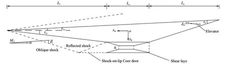
Eig.1 Geometries of typical waverider
1.2 Aerodynamics of hypersonic vehicle
In order to obtain the required aerodynamic for modeling,oblique shock and Prandtl-Meyer expansion theory could be used to estimate the surface force in the study of hypersonbic vehicle modeling.In different flight conditions,the shock effects on forebody,the engine combustion chamber and the aftbody expansion surface of the hypersonic vehicle are considered.The force on the surface of the vehicle is estimated by studying the flow relationship between the shock and flight state.
Eor the hypersonic vehicle configuration shown in Eig.1,attack angle isα,and lower forebody turn angle related with xBaxis isτ1l.If flow turn angleδs=α+τ1l≥0°,oblique shock theory is used to estimate the pressure on the surface of forebody P and temperatures
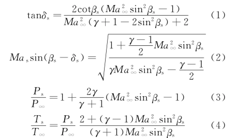
where Ma∞,P∞,T∞are the Mach number,pressure,and static temperature,respectively;Mas,Ps,Tsthe Mach number,pressure,and static temperature,after the flow through the shock,respectively;γthe heat ratio;andβsthe shock angle.
Otherwise,if the flow turn angleδs=α+ τ1l<0°,then the expansion wave appears on the forebody surface of the vehicle,and Prandtl-Meyer theory could be used to estimate the pressure on the forebody surface of the vehicle[6,12].Let δ=-δs,airflow parameters(Mas,Ts,Ps)after the expansion wave is
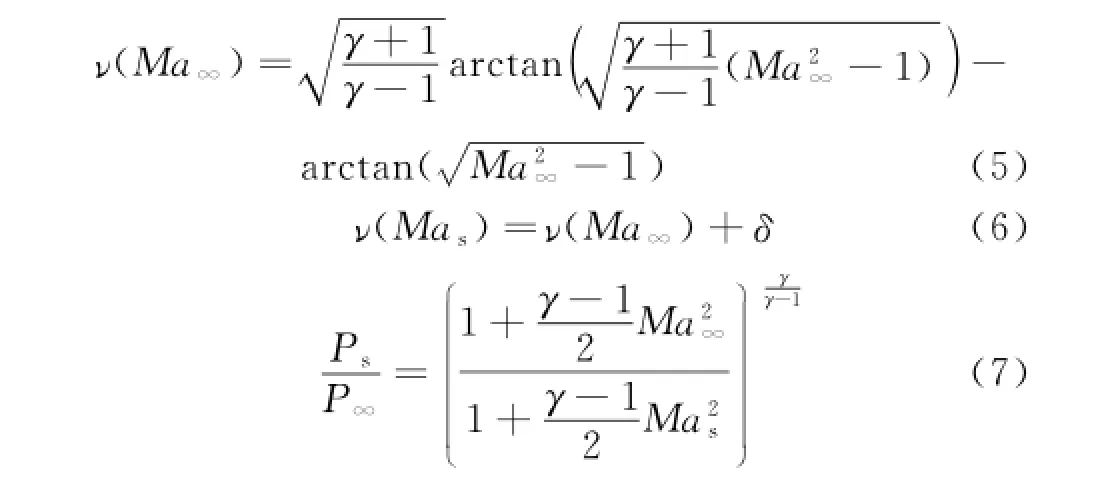
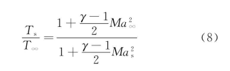
whereυ(Ma)is the Prandtl-Meyer function,whose value is determined by the heat ratioγand the mach number of the airflow.
Therefore,the pressure on the lower forebody can be resolved along with the x and z bodyaxis components
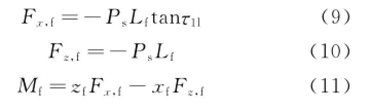
where Lfis the length of forebody shown in Eig.1,(xf,zf)the coordinate that is the aerodynamic center of forebody with regard to the aircraft center of gravity.
Similarly,the aerodynamic force and moment on the upper surface Fx,u,Fz,u,Mu,the aerodynamic force and moment on the lower surface Fx,n,Fz,n,Mn,and the aerodynamic force and moment on the control surface Fx,cs,Fz,cs,Mcscan be obtained by oblique shock theory and Prandtl-Meyer theory.
It is noted that when airflow entering the engine,the airflow direction will change from parallel to the forebody to parallel to the engine axis. This is because the flow will get through the new shock layer.Here a single reflect shock is used to model the new shock layer.Using Eqs.(1—4)and the oblique shock theory,the further compressed airflow parameters(Ma1,T1,P1)can be obtained,here,Ma1is the Mach number of the compressed airflow,T1the temperature and P1the pressure.Thus the additional force and moment are[4]
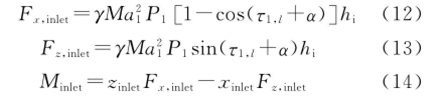
where hiis the height of engine inlet,(xinlet,zinlet)the coordinate of the flow turning point with respect to the center of gravity.Besides,the flow engine nozzle exhausted will expand and form a shear layer as a result of generating pressure on the aftbody.According to Prandtl-Meyer theoryand shear layer approximate pressure formula[4]
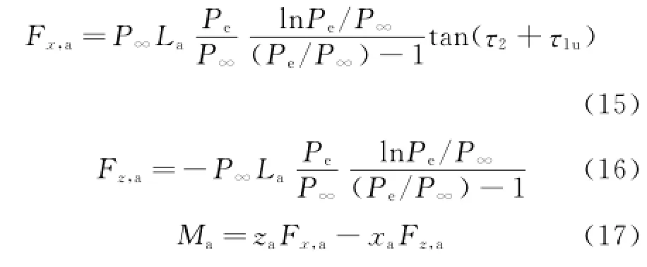
where(xa,za)is the coordinate of aftbody aerodynamic center relative to the aircraft center of gravity and Pethe pressure of the inner nozzle of the engine.
According to principle of force synthesis,the aerodynamics effect on the airframe axis x and z of the hypersonic vehicle are

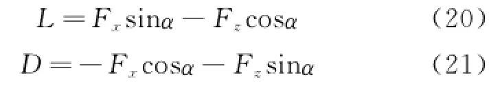
The lift and drag force expression by coordinate transformation are as follow
Aerodynamic pitching moment is

1.3 Thrust of hypersonic vehicle
A quasi-one-dimensional Rayleigh flow with heat increase is used to estimate the scramjet thrust of hypersonic vehicle,as shown in Eig.2[7].The engine model comprises three parts:a diffuser chamber,a combustion chamber,and an inner nozzle,that is,parts①②③in Eig.2,respectively.The fluid in the diffuser and inner nozzle is assumed to be a one-dimensional entropic flow,and the fluid in the combustion chamber is characterized as a one-dimensional flow with heat increase in the tube with the constant area.In this paper,only the stoichiometric ratioφis considered as the engine input,and diffuser area ratio is fixed value Ad=1.
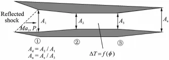
Eig.2 Schematic of scramjet engine
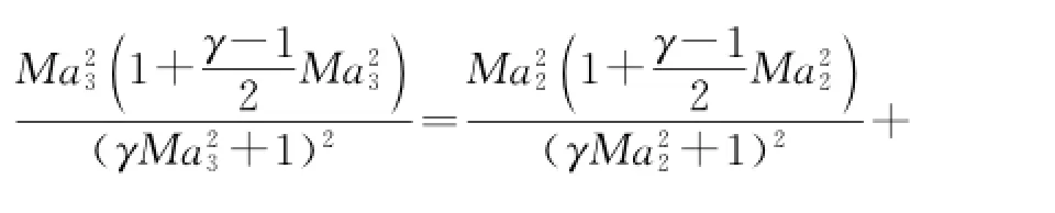
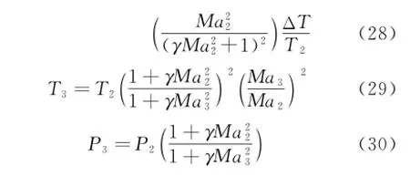
In the diffuser,continuity equations(mass conservation)is applied to calculate the Mach number Ma2,temperature T2,and pressure P2in the diffuser exit

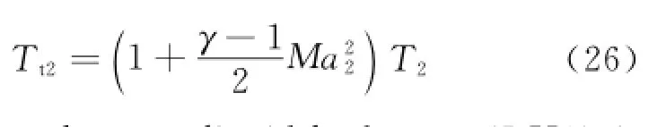
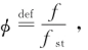
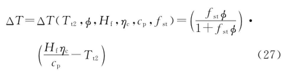
where Hf=119 789 kJ/kg is the heat of reaction for liquid hydrogen(LH2),ηc=0.9 the combustion efficiency,cp=1 004.832 J/(kg·K)the specific heat of air at constant pressure,fst= 0.029 1 the stoichiometric fuel-to-air ratio for LH2.Once the temperature increment is confirmed,according to classic one-dimensional Rayleigh flow relationship,the Mach number Ma3,temperature T3,and pressure P3of the combuster exit are easily obtained[7].
1.4 Aeroelasticity modeling of hypersonic vehicle
The typical hypersonic vehicle is slender waverider configuration,which is approximately equivalent to a single free-free Bernoulli-Euler beam.The bending vibration differential equation of a single free-free Bernoulli-Euler beam is[9]
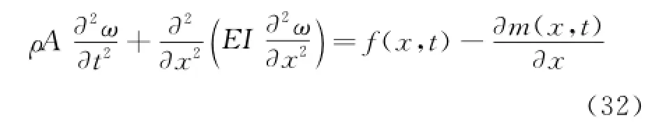
where f(x,t)and m(x,t)are used to denote the external force and moment distributed on per unit length beam,respectively.
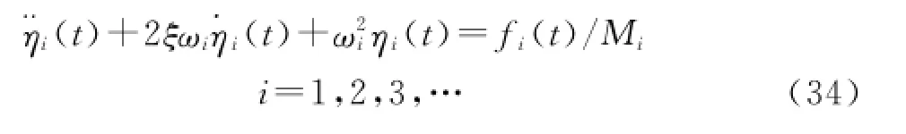
The method of variable separation is applied to solve Eq.(32).Introducing principal coordinate transformation,the natural frequency ω(x,t)can be expressed by the natural mode of vibrationΦi(x)


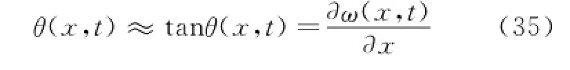
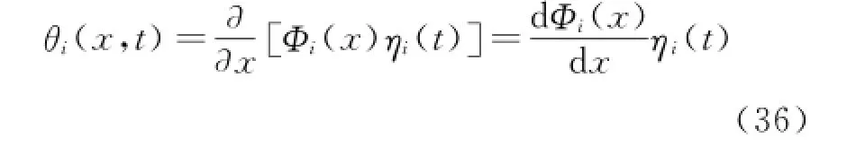
The method of separate variable is utilized again,and the corresponding deflection angle θi(x,t)of the i th order natural mode of vibration can be expressed asthe force of vibration mode.Here the corresponding f(x,t)and m(x,t)are the aerodynamic force and distribution of aerodynamic moment,respectively.
The elastic deformation on the tip of nose of the airframe will change the attack angle of the aircraft,and the elastic deformation on the afterbody of the airframe will change the deflection angle of the control surface correspondingly[13].The change in the forebody attack angle can be approximated given by the deflection angle on the end of the craft noseθi(0,t).Considering the first three-order of vibration mode,the corresponding attack angle change isΔα.Similarly,the deflection angle of aftbody control surface θi(xδe,t)approximates to the change of control surface attack angle,and the corresponding change of control surface angle isΔδe.So the attack angle and control surface after elastic deformation change toα=αr-Δαandδe=δe,r-Δδe,where the subscript″r″means a situation of rigid body.
The assumed modes method(based on a global basis)is used to obtain natural frequen-cies,mode shapes,and finite-dimensional approximants[6,14].It results in a model whereby the rigid body dynamics influence the flexible dynamics through generalized forces.When the associated beam model is assumed to be made of titanium with a dimension of 30.48 m in length,0.244 m in height,and 0.304 8 m in depth,the nominal modal frequencies areωf1=22.2 rad/s,ωf2=48.1 rad/s,ωf3=94.8 rad/s as a consequence.Hence,it ensures that the beam model and the vehicle have the same vibration characteristics.
1.5 Rigid-elastic dynamics model
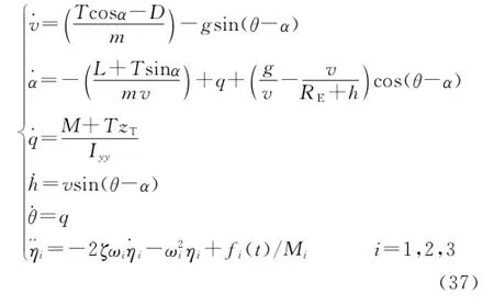
Considering the influence of the earth′s curvature,it is assumed that the thrust direction is along with the engine axis,which is parallel to the airframe axis.Take the fuel stoichiometric ratio of combusterφand elevatorδeas the input,and choose the flight state variable X=[v,α,q,h,θ,η1,˙η1,η2,˙η2,η3,˙η3]T,where velocity v,attack angleα,pitching angular velocity q,height h and pitching angleθare rigid modal;andηi,˙ηi(i=1,2,3)are elastic mode.Lagrangian method is used to deduce the nonlinear equations of longitudinal model of hypersonic vehicle[15]
2 Simulation of Rigid-Aeroelasticity Coupling for Hypersonic Vehicle
The aim of this paper is to illustrate the characteristics of the rigid-aeroelasticity coupling model for a general regularity.Eurthermore,the accuracy of aerodynamic force estimated by oblique shockwave theory and Prandtl-Mayer equation has been demonstrated[12].Within the current model,forebody deflections influence the rigid body dynamics via the oblique shock which influences engine inlet conditions,thrust,lift,drag,and moment.Aftbody deflections influence the attack of angle seen by the elevator.As such,flexible modes influence the rigid body dynamics. Hence the model accuracy can meet the needs of the analysis of control-oriented characteristics for the rigid-aeroelasticity coupling model.
2.1 Selection of geometric parameters
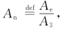
Select the front edge point as the origin of coordinates,directions of x and z axes are shown in Eig.1.The geometric parameters are:total length Lv=30.48 m,forebody length Lf= 14.33 m,aftbody length La=10.06 m,lower forebody turn angleτ1l=6.2°,upper forebody turn angleτ1u=3°,aftbody turn angleτ2= 14.34°;engine inlet height hi=1 m,diffuse chamber area ratio Ad=1,inner nozzle area ratio An=6.25;control surface effective area Ae= 1.58 m2,position(-25.9,1.1),mass m= 2 000 kg,rotary inertia around axis y Iyy=5× 10⁵kg·m2,gravity center position(-16.8,0),elastic mode dampingζ=0.02,and the aeroelasticity modal frequenciesωf1=22.2 rad/s,ωf2= 48.1 rad/s,ωf3=94.8 rad/s.As the aeroelasticity mode is considered,the mass-normalized mode shapes and derivatives of the vehicle′s transverse vibration are shown in Eig.3.
2.2 Simulation of hypersonic vehicle static characteristics
本课程多媒体教学资源构建主要目的在于制作合适本门课程的教学动画、视频和相关素材搜集整理和整合,适当延长微课时间,增强知识点间衔接,授课过程中侧重课后及课堂练习的运用。
In a Matlab environment,we separately trim the rigid body model and the model considering the first three-order aeroelasticity,and the trimstates of the two shown in Tables 1,2.
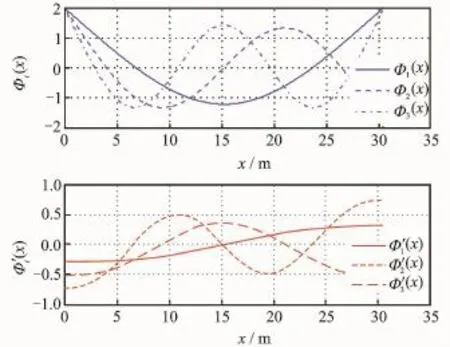
Eig.3 Mass-normalized mode shapes of vehicle′s transverse vibration
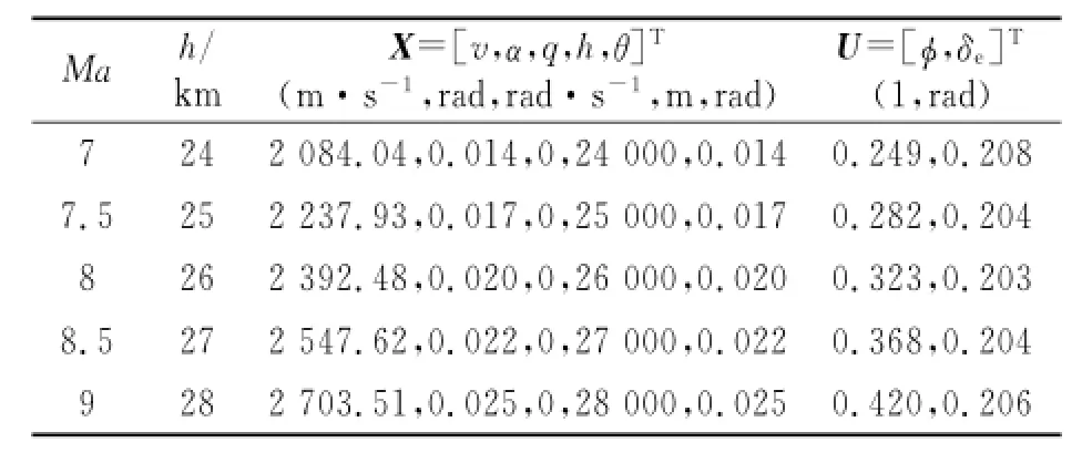
Table 1 Trim states in the given flight condition(rigid)
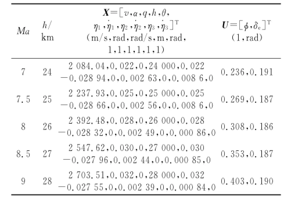
Table 2 Trim states in the given flight condition(considering aeroelastic)
Compared Table 1 with Table 2,when the aeroelasticity is considered,the elastic deformation of the airframe will induce changes of the attack angle of balance point and control input.To better elucidate the problem,through simulation and analysis,Eig.4 illustrates the transverse deformation excited by aerodynamic force and moment in the condition of Mach number 8 and height 26 km level flight.
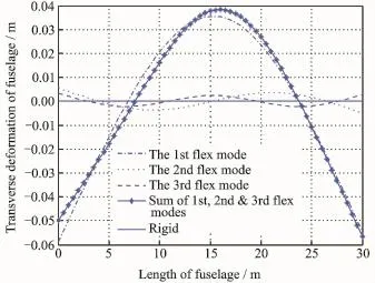
Eig.4 Transverse deformation of fuselage under the condition:Ma=8,h=26 km level flight
Erom Eig.4,the transverse deformation of the fuselage caused by the first-order aeroelasticity is almost the same as that caused by the first three-order aeroelasticity.It means the one-order aeroelasticity is most influential on the vehicle.
2.3 Simulation and analysis of dynamic characteristics
The effect of aeroelasticity on the short period mode is analyzed as follows.Using the values of trim state obtained in Section 2.2,one can approximately linearize the longitudinal non-linear model of hypersonic vehicle in the given Mach number and flight height with the small perturbation linear equation

where the state of a model of rigid body is defined as

And the state of a model of rigid-aeroelasticity coupling is defined.

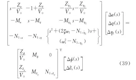
Now the short period mode is considered,let v=0,θ=0,h=0.Eurthermore,the problem is simplified,which is analyzed only in consideration of the first-order aeroelasticity.Therefore,we have the short period motion equation of the first-order aeroelasticity coupling mode,written in a polynomial matrix form via Laplace transformation[11]
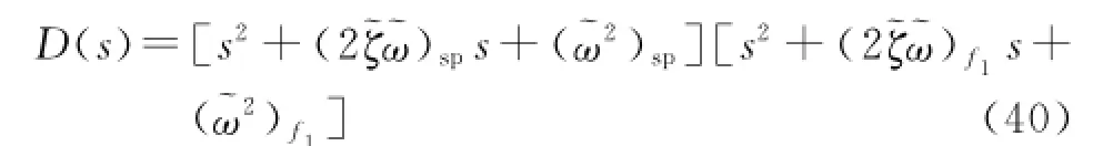
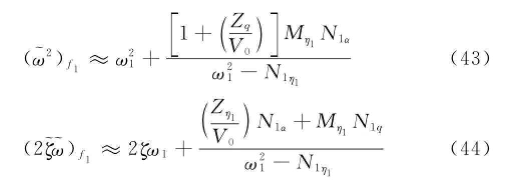
The short period characteristic polynomial of the first-order aeroelasticity coupling has the form as follow,which is a new short period and the first-order aeroelasticity mode.
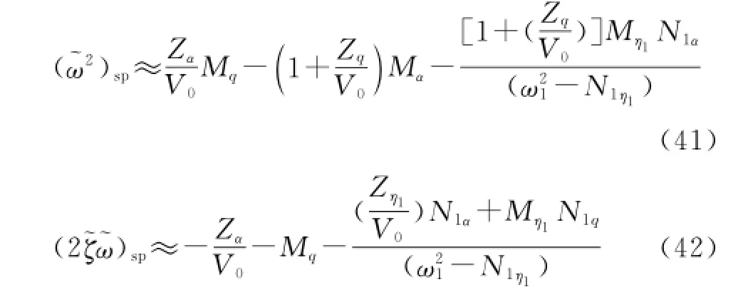
Similarly,the new polynomial coefficient of the first-order aeroelasticity in Eqs.(43—44)can be otained.The first items in the right side of Eqs.(43-44)are single aeroelasticity mode coefficient.
The effects of aeroelasticity mode and short period coupling mainly reflect in the rest parts in the right side of Eqs.(41—44).And it is exactly the existence of rigid-aeroelasticity coupling terms
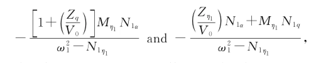
thus leading to a greater effect on the short period mode of vehicle considering aeroelasticity than that considering rigid body vehicle.
Eor further elucidating the problem,choose Ma=8,h=26 000 km level flight,and the corresponding coefficient matrixes of rigid body model and rigid-aeroelasticity coupling model are obtained respectively.Then the eigenvalues of simulation are given in Table 3 correspondingly.
In Table 3,the phugoid modes of both rigid body model and rigid-aeroelasticity coupling model are close to imaginary axis,leading to neutral stability.The height mode is almost unchanged,and the change of short period mode is more significant.Besides,the aeroelasticity mode affects short period mode significantly.
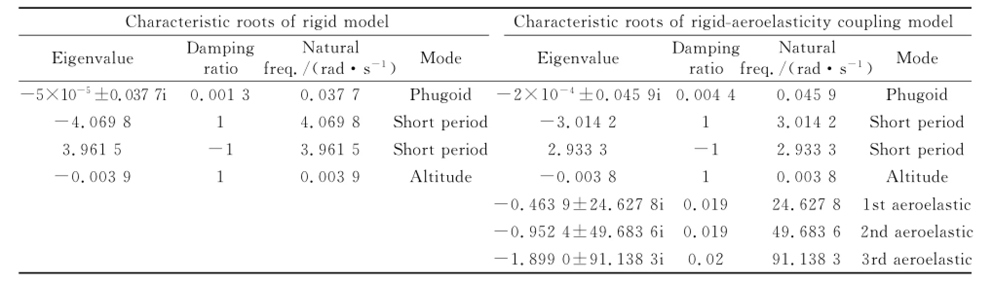
Table 3 Characteristic roots of rigid and rigid-aeroelasticity coupling model under the given flight condition
Generally,since aerodynamical moment and aeroelasticity are deeply influenced by center of gravity and mass distribution,the characteristic roots of rigid and rigid-aeroelasticity coupling model are compared by moving the center of gravity.When the center of gravity is moved forward and back wards,the eigenvalues of simulation are listed in Tables 4,5 correspondingly.
Erom Tables 4,5,it is obvious that the conclusion drew above is universal.

Table 4 Characteristic roots of rigid and rigid-aeroelasticity coupling model in the given flight condition(with CG moving forward)

Table 5 Characteristic roots of rigid and rigid-aeroelasticity coupling model in the given flight condition(with CG moving backwards)
3 LQR Control Compared Simulation of Rigid and Rigid-Aeroelasticity Coupling Hypersonic Vehicle
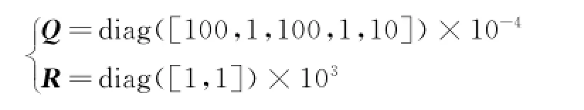
Eor the rigid body model,take quadratic performance index
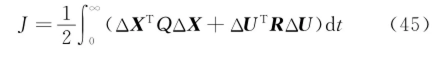
where
When solving the algebra Riccati equation

the positive definite solution P is obtained.
According to linear quadratic regulator(LQR)theory,the state feedback gain matrix
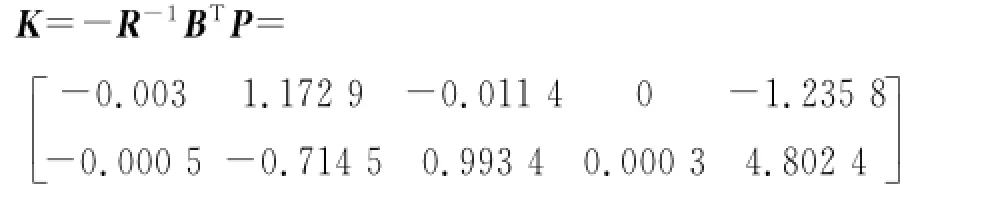
Hence,the control law of the non-linear model is described by
where the superscript″*″represents the input and state of the balance point.Eurthermore,we add the initial disturbance to the balance point,and substitute the control law into the rigid body model.The corresponding state response and input response of the vehicle are shown in Eigs.5,6.

Eig.5 State responses of rigid model
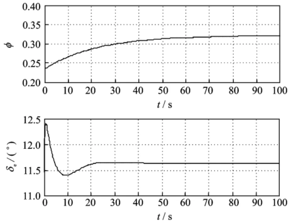
Eig.6 Input responses of rigid model
Substituting the control law of rigid body model into the rigid-aeroelastic coupling model,we gain the state response and input response of vehicle rigid body mode and aeroelastic mode,as shown in Eigs.7—9.
Erom Eig.5,when the initial disturbance exists,the effect on the designed control law is favorable.Known from Eig.6,the input is within reasonable value during the input response process.Every state and input of the vehicle approach to the nominal value.In Eigs.7—9,when the effect on vehicle aeroelasticity is considered,the control law designed according to rigid body model will not be able to meet the control effect,especially the short period modesα,q.The aeroelastic modes will gradually divergent.Thus,a great challenge for controller design is posed when the vehicle is a slender body due to the rigid-aeroelastic coupling.
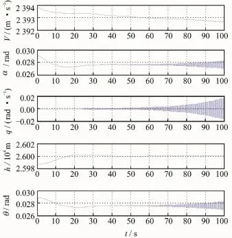
Eig.7 Rigid state responses of rigid-aeroelastic coupling model
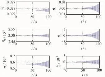
Eig.8 Elexible state responses of rigid-aeroelastic coupling model
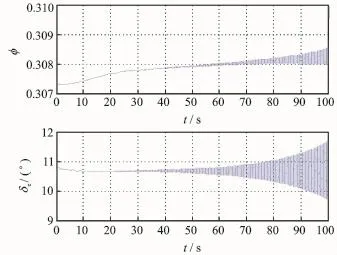
Eig.9 Input responses of rigid-aeroelastic coupling model
4 Conclusions
A dynamic model of rigid-aeroelasticity coupling for hypersonic vehicles is established.By theoretical analyses and simulation comparison of the control-oriented characteristics of the rigidaeroelasticity coupling model,one can draw the conclusion that when the vehicle is a slender body due to the rigid-aeroelastic coupling,its short period mode is greatly affected by the aeroelasticity,which is innegligible.
[1] Liu Yanbin,Lu Yuping.The new modeling method of aerodynamic and dynamic integration facing control study for hypersonic vehicle[J].Chinese Journal of Computational Mechanics,2011,28(1):31-36.(in Chinese)
[2] Kelkar A G,Vogel J M,Whitmer C E.Design tool for control-centric modeling,analysis,and trade studies for hypersonic vehicles[R].AIAA 2011-2225,2011.
[3] Kelkar A G,Vogel J M,Inger G.Modeling and analysis framework for early stage trade-off studies for scramjet-powered hypersonic vehicles[R].AIAA-2009-7325,2009.
[4] Bolender M A,Doman D B.Nonlinear longitudinal dynamics model of an air-breathing hypersonic vehicle[J].Journal of Spacecraft and Rockets,2007,44(2): 374-386.
[5] Rodriguez A A,Dickeson J J,Cifdaloz O,et al. Modeling and control of scramjet-powered hypersonic vehicles:Challenges,Trends,&Tradeoffs[R]. AIAA 2008-6793,2008.
[6] Rodriguez A A,Dickeson J J,Sridharan S,et al. Control-relevant modeling,analysis,and design for scramjet-powered hypersonic vehicles[R].AIAA 2009-7287,2009.
[7] Sigthorsson D O,Serrani A.Development of linear parameter-varying models of hypersonic air-breathing vehicles[R].AIAA 2009-6282,2009.
[8] Sigthorsson D O,Serrani A,Bolender M A,et al. LPV control design for over-actuated hypersonic vehicles models[R].AIAA 2009-6280,2009.
[9] Hughes H,Wu Een.H-infinity LPV state feedback control for flexible hypersonic vehicle longitudinal dynamics[R].AIAA 2010-8281,2010.
[10]Vaddi1 SS,Sengupta P.Controller design for hypersonic vehicles accommodating nonlinear state and control constraints[R].AIAA 2009-6286,2009.
[11]Newman B,Schmidtt D K.Numerical and literal aeroelastic-vehicle-model reduction for feedback control synthesis[J].Journal of Guidance,1991,14(5): 943-953.
[12]Liu Yanbin,Zhang Yong,Lu Yuping.Integrated design on aerodynamic,propulsion and control for deformable waverider[J].Journal of Nanjing University of Aeronautics&Astronautics,2011,43(2):252-253.(in Chinese)
[13]Wang Liang,Chen Huaihai,He Xudong.Modal frequency characteristics of axially moving beam with supersonic/hypersonic speed[J].Transactions of Nanjing University of Aeronautics and Astronautics,2011:28(2):163-168.
[14]Li Zhaofei,Chai Yi,Li Huafeng.Eault feature extraction method of vibration signals base on multifractal[J].Journal of Data Acquisition and Processing,2013:28(1):34-41.(in Chinese)
[15]Torrez S,Driscoll J,Bolender M,et al.Effects of improved propulsion modeling on the flight dynamics of hypersonic vehicles[R].AIAA 2008-6386,USA: AIAA,2008.
(Executive editor:Zhang Tong)
V271.9 Document code:A Article ID:1005-1120(2015)01-0070-11
*Corresponding author:Xiao Liping,Associate Researcher,E-mail:xiaolp@nuaa.edu.cn.
How to cite this article:Xiao Liping,Zhang Yong,Lu Yuping.Control-oriented modeling and simulation on rigid-aeroelasticity coupling for hypersonic vehicle[J].Trans.Nanjing U.Aero.Astro.,2015,32(1):70-80.
http://dx.doi.org/10.16356/j.1005-1120.2015.01.070
(Received 11 November 2014;revised 3 January 2015;accepted 12 January 2015)
猜你喜欢
新教育(2022年32期)2022-12-16
Chinese Physics B(2022年7期)2022-08-01
做人与处世(2022年6期)2022-05-26
做人与处世(2022年4期)2022-05-26
科学咨询(2021年3期)2021-01-02
书香两岸(2020年3期)2020-06-29
科技视界(2020年4期)2020-04-26
数学学习与研究(2018年6期)2018-11-30
课程教育研究(2018年21期)2018-07-18
小学科学·教师版(2016年4期)2016-05-06
 Transactions of Nanjing University of Aeronautics and Astronautics2015年1期
- Transactions of Nanjing University of Aeronautics and Astronautics的其它文章
- CRB for 2-D DOA Estimation in MIMO Radar with UCA
- Flight Dynamic Analysis of Hypersonic Vehicle Considering Liquid-Solid Coupling
- Tradeoff Analysis of Factors Affecting Longitudinal Carrier Landing Performance for Small UAV Based on Backstepping Controller
- Improved Shuffled Frog Leaping Algorithm Optimizing Integral Separated PID Control for Unmanned Hypersonic Vehicle
- Beamforming of Whole Airspace Phased Array TT&C System Based on Linear Subarrays
- Trim Drag Prediction for Blended-Wing-Body UAV Configuration