
Prediction of ship-ship interactions in ports by a non-hydrostatic model*
2015-12-01 02:12ZHOUMinggui周明贵ZOUZaojian邹早建ROELVINKDanoSchoolofNavalArchitectureOceanandCivilEngineeringShanghaiJiaoTongUniversityShanghai200240Chinamailzhouyang20426com2StateKeyLaboratoryofOceanEngineeringShanghaiJiaoTongUniversity
水动力学研究与进展 B辑 2015年6期
ZHOU Ming-gui (周明贵), ZOU Zao-jian (邹早建),2, ROELVINK Dano. School of Naval Architecture, Ocean and Civil Engineering, Shanghai Jiao Tong University, Shanghai 200240,China, E-mail: zhouyang204@26.com2. State Key Laboratory of Ocean Engineering, Shanghai Jiao Tong University, Shanghai 200240, China. UNESCO-IHE, Deltares and Delft University of Technology, 260 DA Delft, The Netherlands
Prediction of ship-ship interactions in ports by a non-hydrostatic model*
ZHOU Ming-gui (周明贵)1, ZOU Zao-jian (邹早建)1,2, ROELVINK Dano3
1. School of Naval Architecture, Ocean and Civil Engineering, Shanghai Jiao Tong University, Shanghai 200240,China, E-mail: zhouyang1204@126.com
2. State Key Laboratory of Ocean Engineering, Shanghai Jiao Tong University, Shanghai 200240, China
3. UNESCO-IHE, Deltares and Delft University of Technology, 2601 DA Delft, The Netherlands
(Received April 23, 2014, Revised January 28, 2015)
Complicated channel geometry and currents may aggravate the interactions between passing ships and berthed ships,which should be evaluated and taken into account in a port design. A method for predicting the ship-ship interactions, based on a non-hydrostatic shallow water flow model, is presented in this paper and is validated by comparing the numerical results with experimental data. The method is subsequently applied to predict the interaction forces acting on a berthed ship due to a passing ship in ports. The influences of the difference of the water depths between the dock and the main channel, the dock geometry, the current and another berthed ship in the dock on the ship-ship interactions are studied. Analysis based on the numerical results is carried out,which is useful for the port design.
ship-ship interactions, non-hydrostatic model, numerical prediction, port design
Introduction0F
With the development of shipbuilding and shipping industry, the ship dimensions increase continuously and the ports are becoming more crowded. The ships berthed in a port may be affected by the hydrodynamic interactions induced by other passing ships. The water movement induced by passing ships can be split into the so-called primary and secondary water movements. The return current and the water level depression together form the primary water movement (also called the “primary wave”). The secondary water movement consists of ship-generated short waves (also called the secondary waves). The shipship hydrodynamic interactions, referred to as effects of a passing ship on a berthed ship in this paper, may cause motions of the berthed ship and the mooring loads, and further lead to disruptions of loading/discharging operations and sometimes dangerous accidents. For large ships passing berthed ships at a low speed, the effects of the passing ship on the berthed ships are mainly associated with the primary water movement. In ports, the channel geometry is complicated and there usually exist currents, wind etc., which may aggravate the passing ship-berthed ship interactions. Therefore, the prediction of the hydrodynamic forces acting on the berthed ships in ports is of great importance for the safety and efficiency of the berthed ship operation and the port design.
In the past decades, the passing ship-berthed ship interactions were studied extensively both experimentally and numerically, mostly for the cases of ships berthed in open water or along a quay wall. Important progress was made in identifying the dominant influence parameters and establishing empirical formulae for the hydrodynamic forces on a berthed ship. Vantorre et al.[1]presented results of ship-ship interaction model tests for a container ship, a bulk carrier and two tankers, with different ship type combinations,ship speeds, passing distances, ship sizes and depthdraft ratios. Based on a regression analysis on the measurement data, empirical formulae for the surge force, the sway force and the yaw moment are established. On the basis of Remery's experimental resultspublished in 1974 and Muga-Fang's results in 1975,Flory[2]presented a set of empirical equations for estimating the peak force and moment that a passing ship exerts on a berthed ship, where the paths of the two ships were essentially parallel. Kriebel[3]conducted physical scale model tests to measure the loads on a berthed ship due to a passing ship moving parallel to the berthed ship. The model tests cover various passing ship speeds, ship displacements, water depths,and separation distances between the two ships. Empirical equations were developed and two existing predictive models were evaluated. Varyani and Vantorre[4]carried out a comprehensive captive model test and developed a semi-empirical generic model to formulate the berthed-passing ship interaction force and moment. This new model can be applied in ship maneuvering and mooring simulators. Huang and Chen[5]used a Reynolds-averaged Navier-Stokes (RANS)based viscous flow solver to explore the effects of a passing ship on a berthed ship in a confined shallow water and the basin geometry, the ship layout, the speed and the standoff distance of the passing ship,and the mooring properties were focused. Li[6]rectified the generic interaction effect model proposed by Varyani based on a regression analysisof ship model test data. With the amended model, results of higher accuracy in shallow waters can be obtained. Sun et al.[7]presented a numerical method for evaluating the forces exerted on a nearby floating structure by shipgenerated waves. The forces for different ship's speeds, dimensions and distances were calculated.
Some studies were carried out under relatively complicated conditions. Pinkster[8,9]presented a method that combined a double-body model with a freesurface model to compute the effects of a passing ship on a berthed ship and obtained good predictions for the ship berthed in open water and along a quay wall. It was subsequently applied to relatively complicated cases where an investigation was conducted for the influence of water depths in fairway, current and other situations. Duffy and Denehy et al.[10,11]assessed the effect that the blockage around a berthed ship had on the interaction force and moment experienced by a berthed ship due to a passing ship. The influence of the blockage on both the form and the magnitude of the interaction force and moment was discussed.
The objective of this paper is to present a numerical method to predict the passing ship-berthed ship interactions in ports. This method is based on a non-hydrostatic shallow water flow model. Firstly, it is validated by comparing the predicted numerical results with measurement data, and then it is applied to calculate the interaction forces on the berthed ship in relatively complicated cases in ports. Finally, the passing ship-berthed ship hydrodynamic interaction is analyzed based on the numerical results and some conclusions are drawn.
1. Mathematical model and numerical solution
A non-hydrostatic shallow water flow model,XBeach, is adopted to study the effects of a passing ship on a berthed ship. XBeach is a 2-D model for wave propagation, long waves and mean flow, sediment transport and morphological changes in the nearshore area, beaches, dunes and back barrier during storms. It is an open-source model developed by a consortium of UNESCO-IHE, Deltares, Delft University of Technology and the University of Miami. The non-hydrostatic module extends XBeach's capability to model nonlinear waves, wave-current interaction and wave breaking in the surf zone. Implementation was done by Smit of Delft University of Technology in cooperation with Deltares and was funded by Deltares[12,13]. The non-hydrostatic formulations closely follow the one-layer version of the SWASH model[14-18].
1.1 Mathematical formulation
The governing equations of the 3-D free surface flow are the continuity equation and the Navier Stokes equations under the assumption that the fluid is incompressible, homogeneous and Newtonian. They can be written in Cartesian coordinates o( x, y, z )(with the o- xy plane lying on the undisturbed free surface, and z -axis pointing upwards) as:

where u=[u( x, y, z, t), v( x, y, z, t), w( x, y, z, t)]is the velocity vector,P( x, y, z)=ρg(ζ-z)+ρp+p0is the pressure (p is the dynamic pressure normalized with the reference density,ρis the density of water, ζ=ζ(x, y, t) is the free surface elevation, and p0is the atmospheric pressure),g=[0,0,-g]is the gravitational body force and⊗means the tensor product of the two vectors.T is the deviatoric viscous stress tensor, which can be expressed as
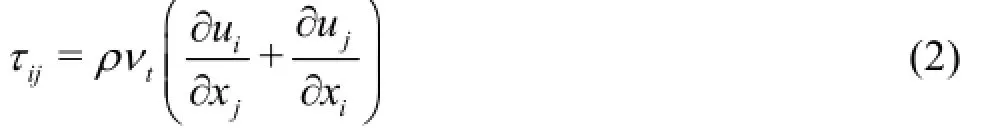
where ntis the eddy viscosity, which is determined from the mean flow variables using a suitable closure model.
To obtain an expression for the free surface, the continuity equation is integrated over the water depth
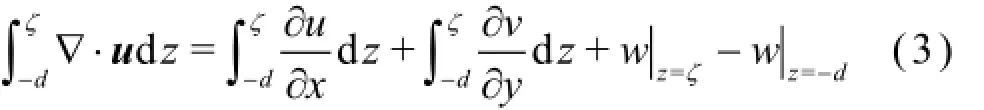
where d=d( x, y)is the bottom position under the assumption that the bed changes are much slower than the fluid motion.
The kinematic boundary conditions at the free surface and at the bottom are:
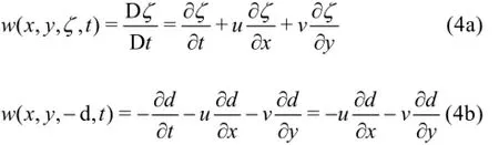
Substituting Eq.(4) into Eq.(3) and applying the Leibniz rule of integration, the integrated continuity equation becomes

where H=ζ+d is the total water depth,U and V are the depth-averaged velocities given by

Integrating the momentum equations in three directions over the water depth and with the application of the Leibniz rule, the depth-averaged equations are obtained as follows:
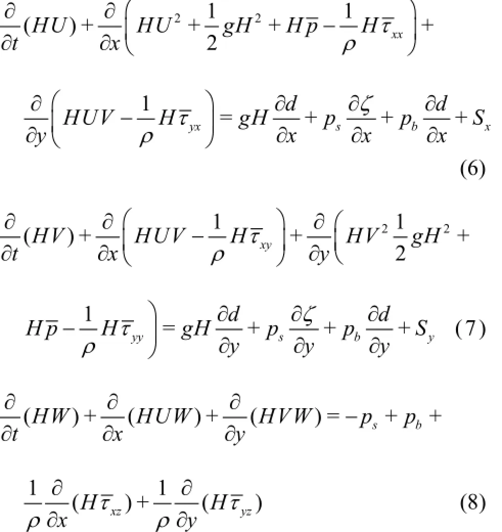
whereWis the depth-averaged vertical velocity,, psand pbare the depth-averaged pressure, the free surface pressure and the bottom dynamic pressure, respectively,are the depth-averaged (turbulent/viscous) stresses,Sxand Syare the source terms due to the stresses at the free surface and the bottom.
Equations (5)-(8) are the depth-averaged non-hydrostatic shallow water equations. In order to close the equations, a Smagorinsky-type sub grid model is used to calculate the eddy viscosity in Eq.(2), which can be expressed as:

where Csis the Smagorinsky constant and Δsis the characteristic length scale of the smallest resolvable eddy.
The boundary conditions for the tangential and normal velocities/stresses are applied along the free surface and the bottom, the closed boundaries and the open boundaries according to Ref.[13] to achieve a unique solution. At the free surface, the normal and tangential stresses are assumed to be continuous, the total pressure is set equal to the atmospheric pressure and taken to be zero. At the bottom, the two tangential stresses due to the bottom friction are specified usingthe discharge through the boundaries is assumed to be zero and the boundaries are fully reflective. At the open boundaries, the gradient of the tangential velocities is set to be zero and only the normal velocity is prescribed in different situations.
1.2 Numerical solutions
In XBeach, the computational domain is bounded by the free surface, the bottom and the four boundaries in between. For the horizontal variable layout, a staggered grid arrangement is employed. The dynamic pressure, the bottom and free surface variables are all assigned at the cell centre and the depth-averaged horizontal velocities are assigned at the cell surface. On the vertical plane, the grid arrangement is non-staggered and both the dynamic pressure and the vertical velocity are assigned at the cell surface.
The governing equations are discretized using different schemes. For the continuity equation, the central difference semi-discretization for the space deri-vative and the Hansen scheme for the coupling between the velocity and the free surface elevation are applied. For the horizontal momentum equations, the approach of Stelling and Duinmeijer[14]is followed to keep the momentum conservative. In the flow expansions, the momentum conservation is applied; in the flow contractions, the energy head conservation is adopted. The advection term is discretized in space and time using a variant of the MacCormack scheme to improve the accuracy of the method. The vertical momentum equation is discretized in a similar manner as the horizontal momentum equations using the MacCormack scheme. The method of Stelling and Zijlema[15], an edge based finite difference scheme in the vertical direction, is implemented within XBeach to construct the non-hydrostatic model. By combining all the equations, a linear system for the non-hydrostatic pressure is obtained which can be written as a penta-diagonal band matrix. To solve the linear system, the strongly implicit procedure (SIP) of Stone(1968) is used[13].
1.3 Representation of a moving ship
The hull form of the sailing ship is represented by a “moving pressure field” applied at the water surface in XBeach, which was implemented by Dano Roelvink at UNESCO-IHE and firstly tested by Ma[19]. To achieve this, the hull of the ship below the waterline is represented by a 2-D depth field defined on a fine rectangular grid. Details of the hull shape can thus be represented, except for features such as a bulb that cannot be represented on a 2-D grid. In such cases the total water displacement below each point on the grid is taken instead.
The movement of each ship (multiple ships can move at the same time) is defined by its 2-D gridded geometry and a ship track is given as a time series of locations (x, y). The heading of the ship is computed from the track or can be prescribed in a separate column of data. During the simulation, the position and the heading of the ship at each time step is interpolated in time, after which the 2-D pressure field caused by the ship is obtained by interpolating the 2-D depths onto the XBeach grid, which is usually coarser. In this interpolation, special care is taken to ensure that the ship's cross-section is accurately represented even on relatively coarse grids.
Because of the representation of the ship as a pressure field, the average squat of a ship is automatically taken into account. However, the ship hull is not stiff and the representation of the secondary waves will not be accurate. As is shown, however, this representation leads to a good description of the primary water movement. No artificially increased viscosity or other methods are required to remove the (inaccurate) secondary waves generated by the model, since they do not affect the flow field or the primary waves in the numerous cases, as have been tested so far. This offers the advantage that the ambient flow field can be modelled accurately in the same XBeach model. From the tested cases, XBeach could well reproduce the shallow water waves withkh smaller than 2.0, where k=2π/λis the wave number andλis the wave length. The present paper only focuses on the primary wave. For the primary waves induced by the ship, the wave length is approximately equal to the ship length Lpp. So the application range of this method should be 2πh/ Lpp<2.0.
In order to avoid (big) initial disturbances, the initial water level in the XBeach model is lowered by the pressure head due to the ship(s). As with physical model tests, each ship has to be accelerated slowly in order to obtain a realistic flow field.
1.4 Computation of forces on berthed ship
In order to compute the forces and moments on berthed ships, each berthed ship is defined in the same way as the moving ships. The pressure at each point on the 2-D grid defining the hull is computed by interpolating the virtual water levels from the XBeach grid (defined as the water levels at the ship locations plus the imposed pressure head) to the fine ship grid. The pressure head at the ship hull is then computed as the distance between the virtual water level and the undisturbed vertical position of the hull. For each panel (grid cell) on the hull the horizontal and vertical forces are then computed, and the total forces and moments are computed by integrating over all cells. All XBeach codes including the adaptations for moving ships and ship forces are of open-source and available through http://xbeach.org.

Table 1 Full scale dimensions of the ships
2. Validation of the numerical method
2.1 Simulation set-up
A series of experiments were conducted by Australian Maritime College in their model test basin facility to investigate the effect of the blockage at the bow and the stern of the berthed ship on the interaction force and moment acting on the berthed ship. The Marad series bulk carrier type hulls were used to represent both the passing ship and the berthed ship.The description of the experiments and the body plan lines of the ship models are given in references[10,11]. In the numerical simulations, the full scale dimensions of the ships are adopted and listed in Table 1. The plan view of the three full scale channel geometries for simulations is shown in Fig.1.
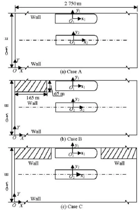
Fig.1 Plan view of the full scale channel geometries for simulations
As shown in Fig.1, the ship is berthed along a vertical quay wall in Case A, while in Case B, the stern of the berthed ship is blocked by a vertical quay wall, in Case C, both the bow and the stern are blocked by vertical quay walls. The berthed ship is fixed at the half length of the simulation domain, and the distance between the portside of the ship and the wall is0.04B . The dimensions of the blockage in Case B and Case C are the same (165 m×65 m). A global earth-fixed coordinate system O( X, Y, Z)and two body-fixed coordinate systems O1( x1, y1, z1)and O2( x2,y2,z2)are established, with the axes ofZ,z1and z2all pointing upwards. There are four boundaries: left boundary (Y =310 m), right boundary(Y= 0 m), upstream boundary (X=0 m)and downstream boundary (X =2 750 m). The static depthhof the domain in all cases is 1.036T.
The track of the passing ship is parallel to the longitudinal centerline of the berthed ship. The passing ship is accelerated from rest to a constant speed Us, which is attained when the mid-ship section of the passing ship is 2.8 times the ship length aft of the mid-ship section of the berthed ship. A constant passing speed is maintained until the mid-ship section of the passing ship is 2.7 times the ship length forward of the mid-ship section of the berthed ship. Both ships are restricted in surge, sway and yaw, and free to roll,pitch and heave. Several passing speeds are re-tested under each condition to check repeatability.
In XBeach, there are 550×62 cells on the free surface, with grid size 5 m×5 m. The ships are represented as a moving pressure field using a finer grid resolution (1 m×1 m) and the pressure head is interpolated into the free surface. “Weakly reflected” boundary conditions are applied on the upstream and downstream boundaries, while “wall” boundary conditions are imposed on the left and right boundaries.
2.2 Validation
The surge force FX, the sway force FYand the yaw moment MZon the berthed ship in different cases are calculated. The results are expressed in nondimensional forms using Eq.(10) and are plotted as a function of non-dimensional passing ship position PD given in Eq.(11).

where XBand XPare the longitudinal coordinates of the berthed ship and the passing ship in the coordinate system O( X, Y, Z),LBand LPis the length of the berthed ship and the passing ship, respectively.
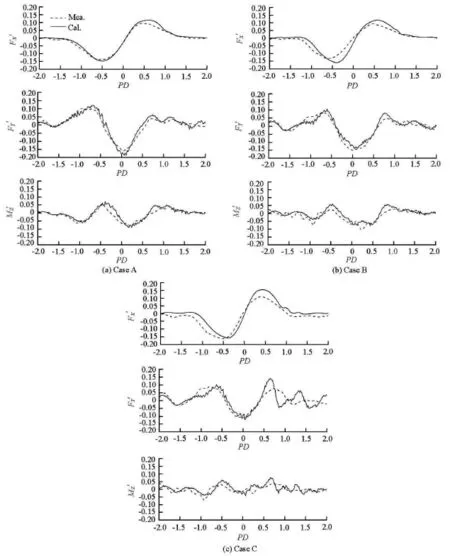
Fig.2 Comparison of non-dimensional interaction forces on the berthed ship in Cases A, B and C
This study focuses on the form and the magnitude of the interaction force and moment on the berthed ship, which are very important for the berthing system. The calculated surge force, sway force and yaw moment during the passing process for the three different channel geometries are compared with the measurement data, as shown in Fig.2. It can be seen from this figure that the form and the magnitude of the interaction forces in Case A agree well with the measured data. In Case B and Case C, especially, in Case C, the discrepancies in magnitude between the numerical results and the measurement data are larger than those in Case A. However, the basic form of the interaction forces is well predicted. Moreover, comparing the results in Cases A, B and C, the berthed ship in Case 3 experiences the greatest peak to peak surge force, the lowest peak to peak sway force and the lowest peak to peak yaw moment among the three cases, the surge force is a little affected while the sway force and the yaw moment are greatly affected by the channel geometry. The above phenomena can be observed in the measurement data as well. The main possible cause for the discrepancies is that the ship geometry represented by a 2-D depth field of both ships is not very accurate and would affect the primary water movement,especially in Cases B and C, where the propagation of the primary wave is complicated. The scale effect in the model test and the numerical test is also a possible cause.
From the validation, it can be concluded that the non-hydrostatic flow model XBeach can give a reasonable prediction of the passing ship-berthed ship hy-drodynamic interactions for different channel geometries.
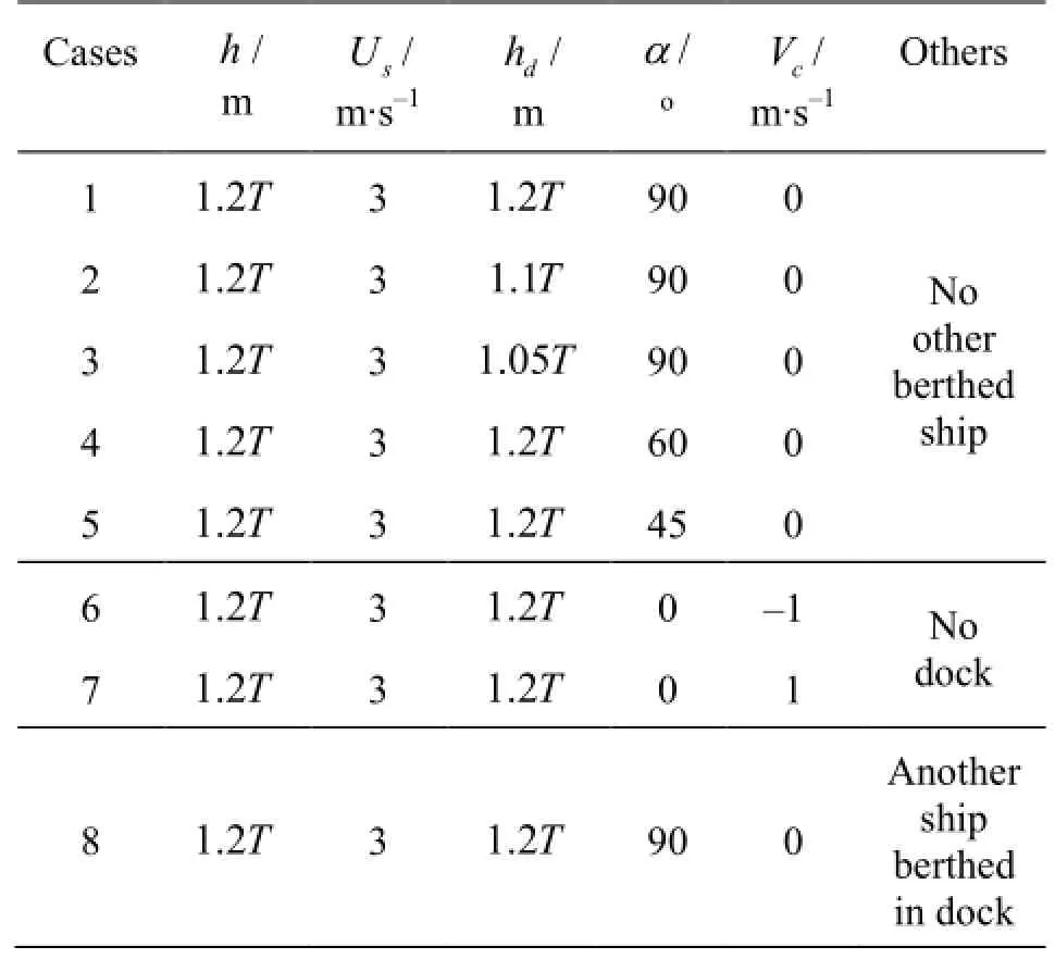
Table 2 Conditions for the numerical simulations
3. Application of the numerical method
3.1 Cases for numerical study
In some ports, the water depth in the dock basin for ship berthing is different from that in the main channel. The water depth difference and other factors such as the current, the geometry of the dock and other berthed ships may influence the effects of the passing ship. In this section, XBeach is applied to predict the effects of the passing ship on the berthed ship in relatively complicated cases, with the factors mentioned above being taken into account. The conditions for the numerical simulations are listed in Table 2.

Fig.3 Plan view for the numerical simulations
The plan view for all the numerical simulations is shown in Fig.3, where a dock basin is considered (except the case with current) which is located at the half length of the simulation domain,hdis the water depth in the dock basin,Vcis the current speed. The same passing ship and berthed ship as in the previous section are used. In order to investigate the influence of the dock geometry on the passing ship-berthed ship interactions, the angleαbetween the centerlines of the main channel and the dock (see Fig.3) takes various values. PointP is the intersection of the centerline of the dock and the left side of the main channel, and its location remains unchanged. The ship is berthed at the left side of the dock and the distance between its portside and the wall is0.04B . Results of the surge force, the sway force and the yaw moment acting on the berthed ship induced by the passing ship under different conditions are obtained and the influences of different factors are analyzed.
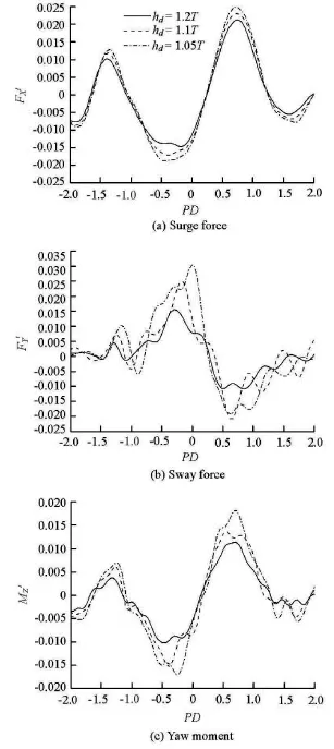
Fig.4 Non-dimensional interaction force and moment on the berthed ship for different hd
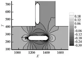
Fig.5 Free surface elevation in Case 3
3.2 Influence of water depths
Non-dimensional results in Case 1, Case 2 and Case 3 are selected to analyze how the difference of the water depths between the main channel and the dock influences the passing ship-berthed ship interactions. The comparison is shown in Fig.4. It can be seen that the magnitudes of the peak force and moment on the berthed ship become larger when hdgets smaller, especially for the sway force and the yaw moment. The positions of the peak force and moment are a little affected by hd. Take the maximum sway force as an example, the magnitude at hd=1.05Tis about twice as large as that at hd=1.2T, the position of the maximum value for hd=1.2T,1.1T and1.05T is PD=-0.29, -0.16 and 0, respectively. In addition, the form of the sway force varies remarkably due to the difference of the water depths. The explanation may be as follows: when hdbecomes smaller, the primary water motion becomes more intense, and the interaction forces get larger, the sway force and the yaw moment are more sensitive to the primary wave than the surge force, so the sway force and the yaw moment increase more than the surge force, the variation of the sway force and the yaw moment may be caused by the different depths between the main channel and the dock. Figure 5 shows the free surface elevation when the moving ship is passing by the berthed ship in Case 3. The water level drops down around the mid-ship and the water level rises around the stern and the bow of the passing ship, as observed, which induces the hydrodynamic forces on the berthed ship.
3.3 Influence of dock geometry
In the design stage of a port, the dimensions and the angleαof the dock should be determined. If α is smaller than 90o, such as α=60o, ships can easily get into the dock and comparatively small dredging cost is needed. However, the dimensions of the dock would be larger than those when α=90o. Definitely, the effects of the passing ship on the berthed ship are different in these cases. In this sub-section, simulations are carried out for Case 1, Case 4 and Case 5 with differentα.
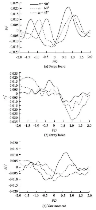
Fig.6 Non-dimensional interaction force and moment on the berthed ship for differentα
In the three cases, the passing ship starts from the same position and the locations of the berthed ship are different.PD is calculated in each case using the positions of O1and O2(see Fig.3). Non-dimensional results of the interaction force and moment on the berthed ship for the three cases are compared with each other in Fig.6. It can be observed that the influence of αon the passing ship-berthed ship interaction effects is complicated. The form and the magnitude of the interaction force and moment see a great difference and the peak values occur at different positions due to the different dock geometries.
For the surge force, when α=90o, the berthed ship experiences the maximum positive surge force at around PD =0.8, which is greater than those when α=60oor 45o. For the sway force, the maximum value becomes larger with the decrease ofα. The maximum values for α=60oand α=45ooccur at PD =1.0, while for α=90othe maximum value occurs at around PD=-0.3. For the yaw moment, the positions of the maximum values are PD=0.3, 0 and 0.5 for α=90o,60oand 45o, respectively. The maximum yaw moment for α=90ois positive while that for the other cases is negative.
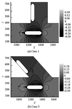
Fig.7 Free surface elevations for Case 1 and Case 5
From the above analyses, it can be seen that, the berthed ship experiences a larger surge force and yaw moment induced by the passing ship when α=90oand experiences a much larger sway force when α= 45o. One possible cause for the difference in the surge force is that when α=60oand α=45o, the bank of the dock has a protection effect on the ship in the surge direction, so the surge force in the case α= 90ois the largest. For the difference in the sway force, the cause may be that, with the decrease ofα, the water level in the positive and negativey directions is more asymmetrical, which leads to a larger sway force. The differences in the interaction force and moment are reflected in the differences of the free surface elevation. As examples, the free surface elevations when the moving ship is passing by the berthed ship in Cases 1 and 5 are shown in Fig.7.
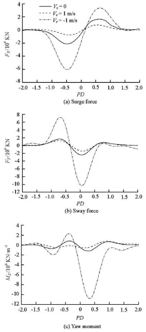
Fig.8 Interaction force and moment on the berthed ship under different currents
3.4 Influence of current
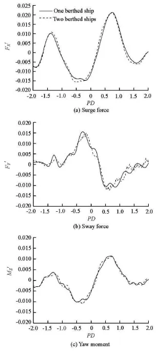
Fig.9 Non-dimensional interaction force and moment on the berthed ship with and without another ship berthed in the dock
The influence of the current on the effects of the passing ship in ports is also an issue that should be considered. In this sub-section, the currents in the same direction (the forward current,Vc=1m/s) and the opposite direction (the backward current,Vc= -1 m/s) of the passing speed are considered in the simulations. Calculations are conducted for Case 6 and Case 7 without dock. The dimensional results are shown in Fig.8, in which the results for Case 1 are also presented for comparison. It should be noted that the current forces acting on the berthed ship are subtracted from the results, since the focus of this study is to investigate the pure influence of the current on the effects of the passing ship. The influence of the current can be observed from Fig.8: when Vc=1m/s, the force and the moment are smaller than those when Vc=0 m/s, while when Vc=-1m/s, the force and the moment are much larger than those when Vc= 0 m/s. The reason is that the magnitudes of the interaction forces depend on the relative passing speed,which in turn depends on the current, hence the interaction forces on the berthed ship are different from those without current. The predicted influence of the current, especially, the backward current, on the passing ship-berthed ship interactions is significant. Thus, the current influence needs to be taken into account in the prediction of the effects of the passing ship.

Fig.10 Free surface elevation in Case 8
3.5 Influence of another berthed ship In some cases, more than one ship may be berthed in the dock. The existence of other ships may change the blockage effect. As an application example,simulation is carried out for Case 8, in which two ships of same ship type are berthed symmetrically along the left and right walls of the dock. The nondimensional results are compared with those of Case 1 and shown in Fig.9. It can be seen that when two ships are berthed in the dock, the peak values of the negative surge force, the sway force and the yaw moment become a little larger, and the form of the three curves is a little different from those when only one ship is berthed in the dock. Therefore, it can be concluded that the interaction force and moment on the berthed ship are slightly affected by another ship berthed in the dock. The explanation may be as follows:when two ships berthed in the dock, it is roughly equivalent to the case where the width of the dock is reduced by one ship's breadth, which will not cause a large difference. The free surface elevation when the moving ship is passing by the two berthed ships is shown in Fig.10.
4. Conclusions
A non-hydrostatic flow model, XBeach, is applied in this paper for predicting the passing ship-berthed ship interactions in ports. The proposed method is validated by comparing the numerical results with measurement data. The numerical calculations are carried out under relatively complicated conditions to investigate the influences of the difference of the water depths between the dock and the channel, the dock geometry, the current and another berthed ship in the dock. From the present study, the following conclusions can be drawn:
(1) The non-hydrostatic flow model gives satisfactory predictions of interaction forces on the berthedship for different channel geometries.
(2) The magnitudes of the peak force and moment on the berthed ship become larger when the water depth in the dock gets smaller, especially, the sway force and the yaw moment. The form of the curves for the sway force and the yaw moment varies remarkably due to different water depths.
(3) The form and the magnitude of the interaction force and moment change a lot due to the dock geometry and the peak values occur at different positions. The berthed ship experiences a larger surge force and yaw moment induced by the passing ship when α= 90oand experiences a much larger sway force when α=45o.
(4) The interaction forces on the berthed ship in the forward current are smaller than those without current, while the interaction forces in the backward current are much larger than those without current. The influence of the backward current on the passing shipberthed ship interactions is stronger.
(5) The interaction forces on the berthed ship are slightly affected by another berthed ship in the dock.
The results and the conclusions of this study are useful for predicting the motions of a berthed ship in ports and may provide guidance for the design of the berthing system and the port. This non-hydrostatic model will be applied to predict the ship-ship interactions under meeting or overtaking conditions in the future study.
Acknowledgements
The authors would like to express their sincere thanks to Dr. Duffy Jonathan and Mr. Denehy Shaun from Australian Maritime College for providing the experimental data.
[1] VANTORRE M., VERZHBITSKAYA E. and LAFORCE E. Model test based formulations of ship-ship interaction forces[J]. Ship Technology Research, 2002,49(3): 124-141.
[2] FLORY J. F. The effect of passing ships on moored ships[C]. Proceedings of Prevention First 2002 Symposium. Long Beach, California, USA, 2002.
[3] KRIEBEL D. Mooring loads due to parallel passing ships[C]. Proceedings of Ports 2007: 30 Years of Sharing Ideas: 1977-2007. San Diego, California, USA, 2007.
[4] VARYANI K. S., VANTORRE M. New generic equation for interaction effects on a moored containership due to a passing tanker[J]. Journal of Ship Research,2006, 50(3): 278-287.
[5] HUANG E. T., CHEN H.-C. Influences of site specifics on passing ship effects[C]. Proceedings of the 16th International Offshore and Polar Engineering Conference. Lisbon, Portugal, 2007, 2356-2363.
[6] LI Xue-dong. Perfect the generic interaction effects model of moored ships in shallow waters[J]. Journal of Jimei University (Natural Science), 2010, 15(2): 119-123(in Chinese).
[7] SUN L., DONG G. and ZONG Z. et al. Numerical analysis of the effects on a floating structure induced by ship waves[J]. Journal of Ship Research, 2011, 55(2):124-134.
[8] PINKSTER J. A. The influence of a free surface on passing ship effects[J]. International Shipbuilding Progress, 2004, 51(4): 313-338.
[9] PINKSTER J. A. Prediction of hydrodynamic interaction effects of vessels in ports[C]. Proceedings of 3rd International Conference on Ship Manoeuvring in Shallow and Confined Water: Ship to Ship Interaction. Trondheim, Norway, 2011, 279-287.
[10] DUFFY J. T., DENEHY S. P. and RANMUTHUGALA D. et al. The effect of berth blockage on berthed shippassing ship interaction[C]. Proceedings of 3rd International Conference on Ship Manoeuvring in Shallow and Confined Water: Ship Behaviour in Locks. Ghent, Belgium, 2013, 237-247.
[11] DENEHY S. P., DUFFY J. T. and RANMUTHUGALA D. and RENILSON M. R. The effect of berthed ship bow and stern blockage on berthed ship-passing ship interaction[C]. Coast and Ports Conference 2013. Sydney, Australia, 2013, 1-7.
[12] SMIT P. B. Non-hydrostatic modelling of large scale tsunamis[D]. Master Thesis. Delft, The Netherlands:Delft University of Technology, 2008.
[13] SMIT P. B., STELLING G. S. and ROELVINK D. et al. XBeach: Non-hydrostatic model[R]. Delft, The Netherlands: Delft University of Technology and Deltares, 2010.
[14] STELLING G. S., DUINMEIJER S. P. A. A staggered conservative scheme for every Froude number in rapidly varied shallow water flows[J]. International Journal for Numerical Methods in Fluids, 2003, 43(12):1329-1354.
[15] STELLING G., ZIJLEMA M. An accurate and efficient finite-difference algorithm for non-hydrostatic free-surface flow with application to wave propagation[J]. International Journal for Numerical Methods in Fluids,2003, 43(1): 1-23.
[16] ZIJLEMA M., STELLING G. S. Further experiences with computing non-hydrostatic free-surface flows involving water waves[J]. International Journal for Numerical Methods in Fluids, 2005, 48(2): 169-197.
[17] ZIJLEMA M., STELLING G. S. Efficient computation of surf zone waves using the nonlinear shallow water equations with non-hydrostatic pressure[J]. Coastal Engineering, 2008, 55(10): 780-790.
[18] ZIJLEMA M., STELLING G. and SMIT P.SWASH: An operational public domain code for simulating wave fields and rapidly varied flows in coastal waters[J]. Coastal Engineering, 2011, 58(10): 992-1012.
[19] MA H. Passing ship effects in a 2DH non-hydrostatic flow model[D]. Master Thesis, Delft, The Netherlands:UNESCO-IHE, 2012.
* Project supported by the National Natural Science Foundation of China (Grant No. 51061130548).
Biography: ZHOU Ming-gui (1985-), Female, Ph. D.
ZOU Zao-jian,
E-mail: zjzou@sjtu.edu.cn

- 水动力学研究与进展 B辑的其它文章
- An effective method to predict oil recovery in high water cut stage*
- Experimental study of breach process of landslide dams by overtopping and its initiation mechanisms*
- Implicit large eddy simulation of unsteady cloud cavitation around a planeconvex hydrofoil*
- Flow hydrodynamics in embankment breach*
- The variations of suspended sediment concentration in Yangtze River Estuary*
- Experimental investigation of motion responses of tunnel element immerging by moored barge*