
Design of Control and Monitor System Applied in Artificial Grass Tufting Machine
2015-12-20 09:14YUYongmin于永民SONGJialing宋佳玲
YU Yongmin(于永民),SONG Jialing(宋佳玲)
1Zhongyuan University of Technology,Zhengzhou 451191,China
2College of Mechanical Engineering,Donghua University,Shanghai 201620,China
Introduction
With the rise of our country's education career and sports,artificial turf is in high demand and it is claiming for a higher quality.Meanwhile,the boom of economy and improvement of life standard make people in great need for artificial turf.Now artificial turf is widely employed in various sports and leisure places such as football field,tennis court,hockey,golf course,integrated playground,amusement park,kindergarten,residential courtyards,parks and business environment.Because artificial turf has more security features,the airport's natural lawn also has a tendency to be replaced by artificial turf[1-2].
Nowadays international tufting machine technologies are mainly in the hands of American Tuftco,British Cobble Company,Japan's Three Industrial Co.,Ltd.,and the CMC companies in the United States[3-4].With the close international cooperation,the tufting industry will have integration,but it will also face an increasing competition.At present,China has not its own tufting technology,and most of the production equipments are imported.All of these are unfavorable for China's tufting industry.Domestic enterprises have begun to recognize the problem,and the voice of localization becomes higher and higher.As a result,many enterprises put human and material resources into studying tufting technology[5-6].
With the development of reform and open policy and the modernization of China's industry,the domestic machinery manufacturing level has been greatly improved,and some enterprises can also manufacture components and parts that meet production requirements through technical transformation.However,the electrical control technology is not widely spread like machinery manufacturing technology,so lack of electrical control technology is a big problem for many small and medium enterprises.How to design electrical control systems based on machinery has become an issue to be considered for enterprises,because this issue affects the further development of enterprises[7].To improve technological level of domestic artificial grass tufting machine and seize domestic market,many enterprises increase more investment to improve the productive status.
1 Control System Overall Design
According to the existing tufting machinery,it adopts servo system to replace the PIV reducer as the control method of this system.The control system of artificial grass tufting machine design which mainly completed electric control system design includes software design and hardware design.
The overall design diagram of the system is shown in Fig.1.In this project,the system is controlled by upper and lower machines.The upper machine is touch screen panel,through the design of the man-machine interface to select the mode of operation,to complete the transmission of speed requirements and alarm signal data to the lower machine.
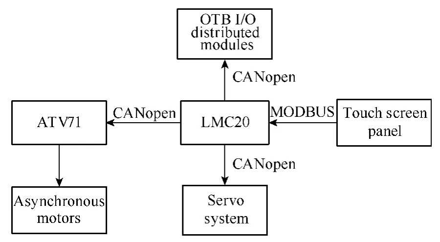
Fig.1 The overall design diagram of the system
The lower one is LMC20which receives data signal and transmits the processed data to ATV71drive and servo systems through CANopen bus.At last,it controlled asynchronous motors,servo motors and spindle motor to change the amount of yarn delivery and turf density and change the comb plate position to achieve the purpose of controlling pile height.Monitor system could select to monitor the state of motor,and then feedback current process parameters to assist the safe production.
2 Safety Module Design
Safety of machinery design,which adopts the advanced safe mechanical technology,analyzes and evaluates the possible risk of the machine from the internal system.According to the results of evaluation,the structure and the protective device and the using information which could make the possible accident under control are designed so that the machine would be safe in the whole life cycle[8].The components of the system are mainly from Schneider production.Great efforts have been put into the safety design of the system and various security modules have been chosen to monitor production safety.Schneider security modules have the advantages of compact size,long serving life and strong security and it chooses XPS-ATE security modules to monitor scramming and starting,door magnetic switch,limit switch and light switch,shown in Fig.2.Door magnetic switch is to monitor whether the door of main drive motor is open or not in production.Light switch is to monitor whether there is any object in dangerous areas in the process of production.Limit switch is to monitor whether gear cases and belt wheel box are opened.Once the above situations happen,machine cannot start or shut off immediately which can prevent potential danger to protect safety of workshop staff and avoid unnecessary loss.
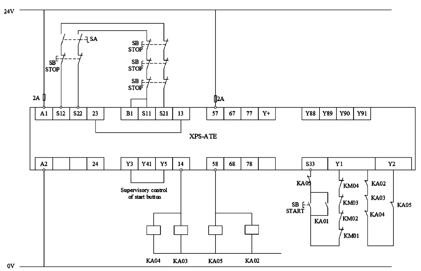
Fig.2 Part of the security module circuit diagram
To enable the circuit to be more secure,reliable and efficient,more phased-relays are increased on circuit.These phased-relays provide phase protection and outage when phase sequence is not correct.Meanwhile,phased-relays also can detect undervoltage,overvoltage and imbalanced phase.
3 Master Control Module Design
CANopen,as an application layer which is open,low-cost and based on controller area network(CAN)bus,has the features of reliability,better real-time and strong antijamming capability and now has been widely used in industrial automation field.According to requirement of grass turf,to regulate the speed of machine tool,this system uses CANopen bus to build the whole control system and variable speed drive to control asynchronous motors.To control the amount of yarn,delivery roller changes speed by servo systems.At the same time,the power of servo systems transmit to thorn roll to control the speed of output and input of fabric.The system bus layout is shown in Fig.3.
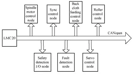
Fig.3 The system bus layout
The system uses CANopen to extend node.Reliability of system communication has been taken into full consideration when designing hardware circuit of CANopen bus interface.
3.1 Program flow
LMC20controlled program flow is shown[9]in Fig.4.There are three operating patterns in the control system:automatic mode,manual mode,and debug mode that can be chosen through touch screen panel in different conditions.The debug mode is applied to debug phase when designing control system.If machine breaks down,manual drive mode is available and automatic drive mode in normal condition.

Fig.4 Program flow
3.2 Design of touch screen panel
Vijeo-Designer is made up of two application programs:image developing software and engineering operation software.Firstly,develop application program in Vijeo-Designer software and then download it into touch screen panel to run the program.After finishing the connection of hardwares in the project,the system should be set in hardware configuration and specific communication parameters of Vijeo-Designer software.Choosing remote terminal unit(RTU)in driver configuration and setting communicating rate as 19 200,system would complete the communication with LMC20.Picture edition should achieve the functions of mode selection,frequency control,shutting off and starting,setting servo system and alarm collection.Variables(being assigned device address)are the bridges of communication between touch screen panel and targeted device.
3.3 Design of LMC20controller
The core of the whole control system is the main control chip whose performance would directly affect result of controlling system.The system adopts LMC20motion controller to achieve communication between machine tool system and the touch screen panel.The resources are distributed as follows:the interface of SUB-D connector connected with spindle encoders to implement measure,RJ45connector connected with touch screen panel to communicate with touch screen panel,HE10used to connect with power input,relay input and output,CANopen connector used to communicate with variable speed drive and OTB module,and LED light monitored the condition of connectors.The design of system software mainly includes transplantation of soft PLC,bus configuration and programming design.
3.3.1 Transplantation of soft PLC and bus configuration
To apply CoDeSys to develop environment to program the device,CoDeSys operation system should be transplanted into controller.The operation system converts industrial personal computer(IPC)into controller which meets standards of IEC61131-3and program for CoDeSys.Different operation system should be transplanted into different operating system and controller hardware[10-12].The transplantation of this thesis aims at CoDeSys operation system under windows operating system.
After transplanting operation system successfully,fieldbus master station and slave station module can be added into CANopen slave station.Electronic data sheet(EDS)documents should be added into CANopen slave station.All of them can be converted into(XML)documents to configure through development environment of CoDeSys[13].In this design,selection of CANopen module as slave station,firstly the OTB module configuration can be completed in the Advantys software,and then turned EDS files into CoDeSys.
3.3.2 Programming design
CoDeSys support six programming languages provided by IEC_61131which can be divided into two kinds:text language and figure language.Text language includes structured text(ST)and instruction list(IL),while figure language contains ladder diagram (LD),function block diagram(FBD),sequential function chart(SFC),continuous function editor(CFC)and so on[14].Developer can pick up the most suitable programming language according to the features of subprogram and functional block in a project to improve flexibility and efficiency developing program.
The input for system includes analog signal module,digital signal and control command signal of sensors.Analog signal module of sensor can convert to digital signal according to comparison value set by converting unit.Protection modules output guarded command according to digital signal of sensor.Control command signal,handled by control unit,outputs the control command to the corresponding parts.After logical analysis,control command and protection command can control the performance of actuator.
3.3.3 CANopen communication
The software of CANopen implements the predefined master/slave connection set while slave station node supports four receiving produce data objects(PDOs),four sending PDOs,one serve data object(SDO),one emergency object and one error node control object[15].According to the characteristics of the communication protocol,software design defines CAN message,receiving and sending of PDO configuration object and CANopen protocol configuration object in the way of structure and finishes reading and writing relative data of object by defining structure pointer which is beneficial for editing program.Besides,performance of object dictionary and process data image can be implemented in the way of defining array.
When SDO message deals with subfunction,reading and writing of object dictionary is implemented by querying array through prime index and sub-index of the object being accessed.The state machines of CANopen I/O salve station read and write the byte codes of the heartbeat message sign in the way of receiving network management(NMT)message command word and then generate transfer procedure.The way of handling of communication object of PDO and SDO is according to the current state indicated by the byte codes of the heartbeat message sign,and the program is shown in Fig.5.
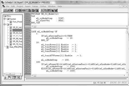
Fig.5 The main program diagram
4 Monitor System Design
4.1 Monitor system overall design
This paper reports on monitor system design.The mo-nitor system includes the following modules:parameters on line reading system,CANopen bus data communication module,online data analysis module and faulting diagnosis module.Based on the analysis of demand,the monitor system function diagram is shown in Fig.6.
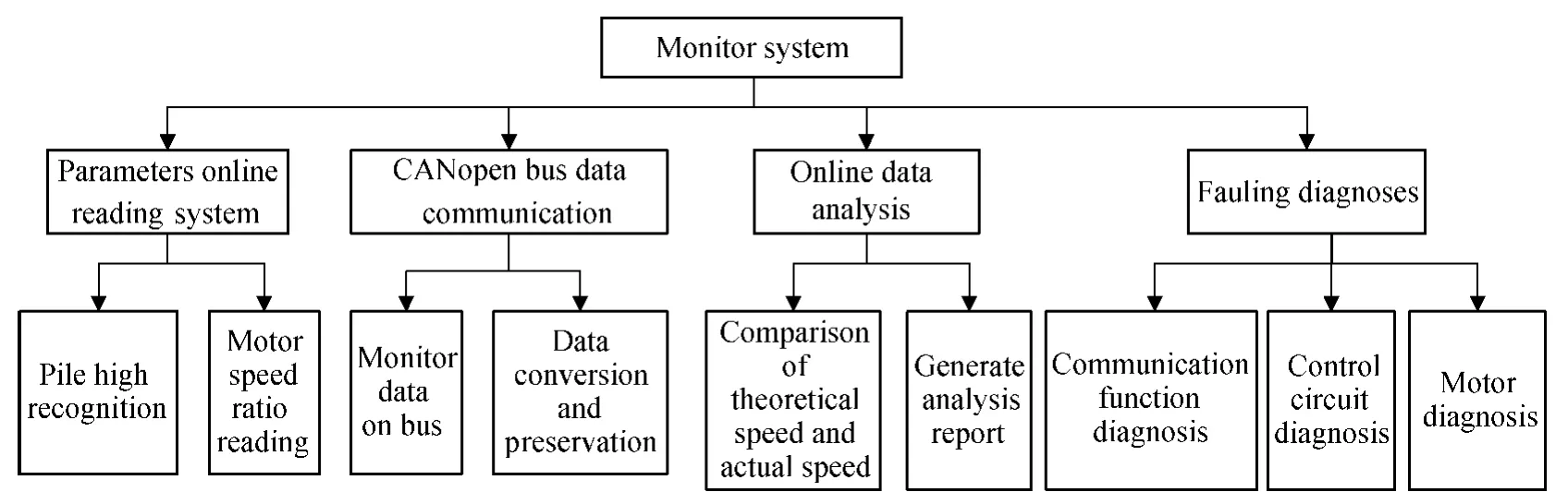
Fig.6 The monitor system function diagram
After initializing the monitor system and connecting to the CANopen bus node,recognition IPC node will be obtained through the information code.Then download data system online parameter to obtain the high information of pile and speed ratio of the motors,and all the parameters would be shown in the interface of the monitor system.Having processed system information,the system selectes the needed monitor motor,such as the spindle motor,licker motor,and roller motor.And having finished the selected motor,the system would start to dynamically analyze the feedback data of motor detection node,and then the system generates the report on the motor characteristics,speed threshold and other parameters.System saving related data documents which is based on the user's needs would be the data source of maintenance for the equipment in the future.The flow program of the system is shown in Fig.7.
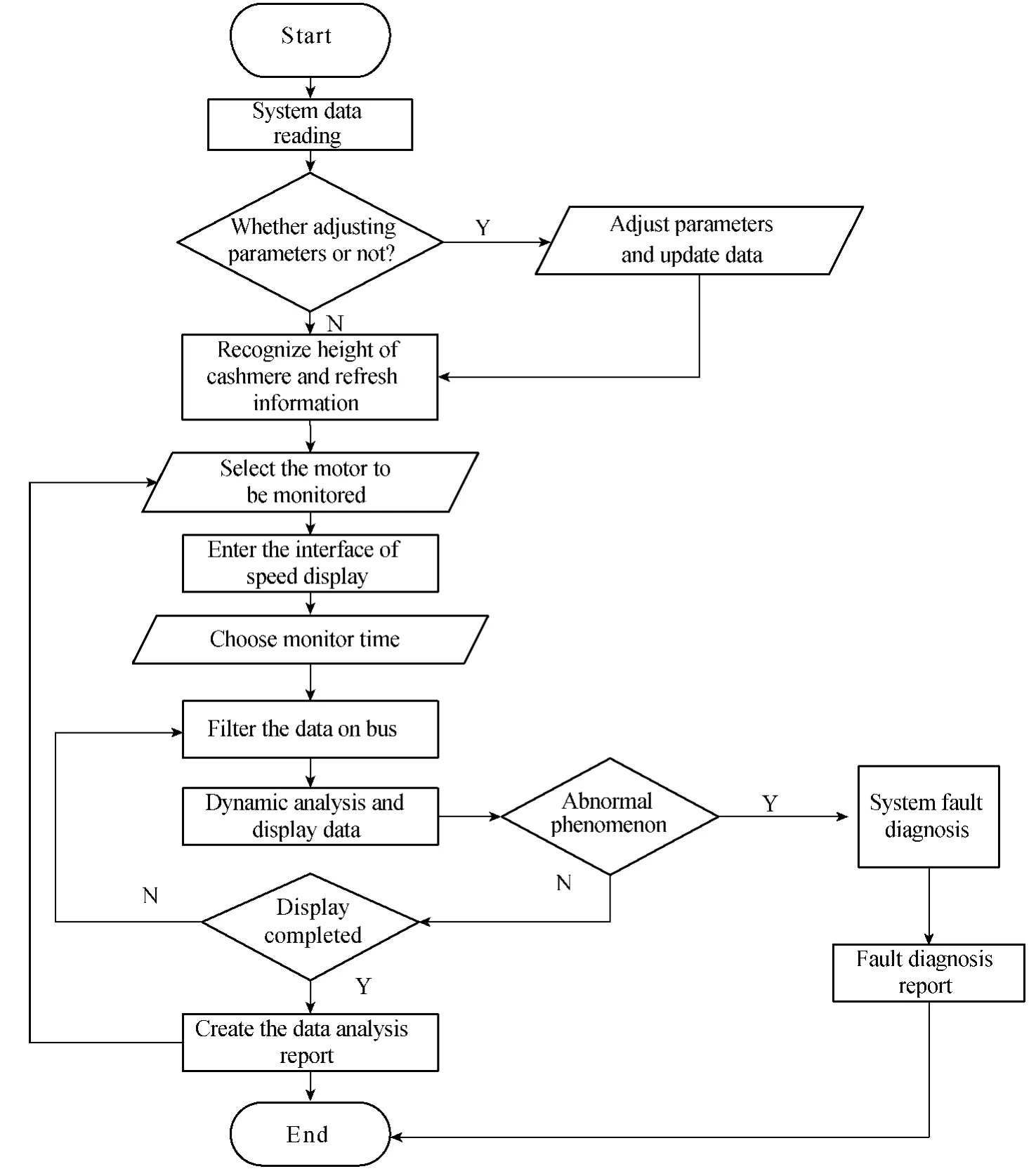
Fig.7 The system flow program
4.2 Analysis of servo motor data
Servo motor data processing includes motor information data reading,speed analysis of servo motor,speed real-time display,generation of final analysis report and data stored as a document.The flow program is shown in Fig.8.
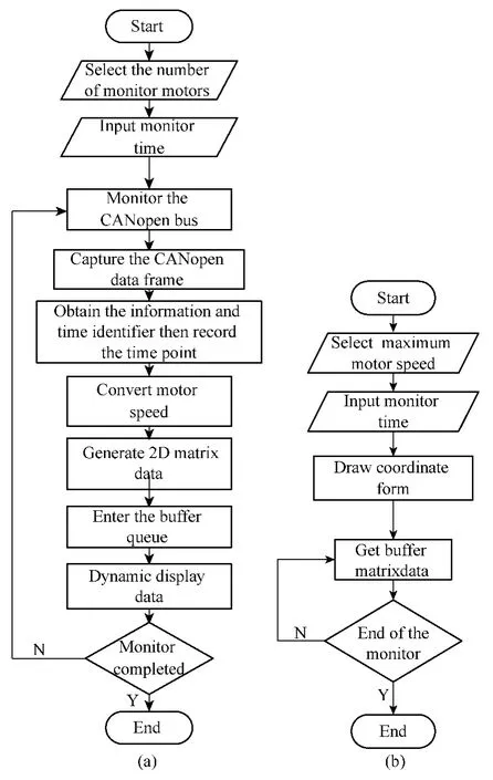
Fig.8 The flow program of information acquisition and dynamic display
Real-time dynamic display of servo motor speed is very intuitive,but the monitor staff will be fatigue while seeing more data.Monitor system design some simple algorithms of velocity analysis to help the monitor staff to analyze the speed of servo motor and generate the report on the speed analysis,and point out the working state of the monitor servo motor.If the servo motor has some bad state,monitor system will provide some reference to judge based on these bad state,and point out the current problems.Finally,the system saved data documents which is based on the monitor personnel's requirement would be the data source to analyze in the future.
4.3 Fault diagnosis of monitor system
Fault diagnosis of monitor system completed the analysis of the monitor status and put forward the corresponding emergency operation suggestion.During the operation or maintenance process,the system determined the corresponding detection with abnormal state feedback to analyze result,and provided the corresponding information and further referenced operation.
The signals of whole control system feedback are basically running state signal of the motor.When the detection system detects the abnormal state,it will automatically enter the fault diagnosis module,identify abnormal state signal of the running motor,and use different fault diagnosis methods to complete the fault judgment.The fault diagnosis module consists of three parts:the fault diagnoses of communication,control circuit,and motor.
The signal anomaly of motor state can be divided into two categories:one type of it is the signal of motor state which is normal,but the fluctuation goes beyond the allowable range.The other type of it is the signal of motor state changes irregularly.To the first kind of abnormal signal,it is the motor that needs doing the fault diagnosis.The second kind of abnormal signal is more complicated.Diagnosis of communication fault should be done so as to determine whether there exist communication problems.If the communication has no problem,the fault diagnosis of the control circuit of motor must be carried on to determine whether there is a fault of the control circuit.If the diagnosis test of control circuit is still normal,it should be determined that whether there is a fault of the motor at last.
5 Field Debugging
After the installation is completed,the field debugging of the whole system will be conducted.It can be divided into upper and lower computers and drive circuit debugging.In sight of safety,it is necessary to conduct debugging in branches of tufting machine and then in the whole system.Some failures appear in the process,and tufting machine can run smoothly after consistent tests finally rotate speed has been 60-500r/min.Once the rotate speed is over 500r/min,instability phenomenon will appear which needs to be solved.At last,manufacturer's requirement of lawn 4 m width and needle density for 1/10in are met.
6 Conclusions
According to the development of control system of artificial grass tufting machine,the thesis puts forward a plan about tufting machine control system of CANopen bus.LMC20motion controller is used to develop I/O slave station based on CANopen protocol,which can implement communication with CoDeSys soft PLC networking.Parameters on line reading system,on-line monitor and data analysis,monitoring over servo motor of tufting machine and analysis of fault diagnosis in abnormal system condition had all been involved in the design work.The system also succeeds in the spot debugging and can meet the production requirements of artificial grass tufting machine which facilitates domestication of grass tufting machine.
[1]Connelly T,Teubert C.Airside Applications for Artificial Turf[EB/OL].(2009-09-30)[2014-09-20].http://www.docin.com/p-661350899.html.
[2]Man D,Bao Y X,Song G L,et al.Research Progress on Strengthening Technology for Turf Bed in the Spots Field[J].Pratacultural Science,2010,27(7):41-47.(in Chinese)
[3]Liu H S.Development Status of Tufted Carpet Technology[J].Beijing Textile Journal,2002,23(3):7-11.(in Chinese)
[4]Toshiyasu K.Weaving Machinery and Its Related Technologies[J].Journal of Textile Engineering,2007,53(2):43-52.
[5]Ding C H,Yang Y Z,Sun Y Z.State and Outlook of Research on Shafting Dynamics of Carpet Tufting Machine[J].Journal of Textile Research,2007,28(8):120-123.(in Chinese)
[6]Card R T,Card J L.High Speed Tufting Machine:US 4665845[P].1987-05-19.
[7]Shen G Y.The Design of Control System for Tufting Carpet Machine[D].Hangzhou:Zhejiang University,2008:1-2.(in Chinese)
[8]Sheng X M,Huang H W,Liu J N,et al.Analysis of Mechanical Safety Design[J].China Mechanical Engineering,2001,12(12):1354-1355.(in Chinese)
[9]Cai C W,Zhang D L,Ren X Y,et al.Computer Control System of Tufting Machine[J].Industrial Control Computer,2003,16(12):24-25.(in Chinese)
[10]Hu Z L,Zeng Z Q,Wu Y,et al.Design and Development of a Fieldbus Monitoring System Based on CoDeSys[J].Control and Automation Publication Group,2012,28(10):122-123.(in Chinese)
[11]Shen C,Long X,Huang B,et al.Implementation of Standard Data Interface CoDeSys-Based Soft PLC[J].Mechanical Engineering &Automation,2014(1):7-9.(in Chinese)
[12]Xie M,Zhang J S,Li L M.The Electric Control System Design of Iron Ladle Car Based on CoDeSys[J].Journal of Hubei University of Technology,2012,27(4):61-63.(in Chi-nese)
[13]Zhang S X,Yang J W,Chen W F.Design on Automatic Const-Weight Packing Machine Control System Based on Soft PLC and CAN-Bus[J].Control &Automation,2005,21(10-1):19-20.(in Chinese)
[14]Wang L L,Kang C F,Ma C M,et al.Design and Implementation of Embedded Soft PLC System Based on CoDeSys[J].Modern Manufacturing Engineering,2007(3):54-56.(in Chinese)
[15]Zhao J G,Yang J W,Sun S W.The Development and Application of CANopen Compliant I/O Slave[J].Control and Automation Publication Group,2007,23(8):9-11.(in Chinese)
 Journal of Donghua University(English Edition)2015年2期
- Journal of Donghua University(English Edition)的其它文章
- Analysis of Co3O4/ Mildly Oxidized Graphite Oxide (mGO )Nanocomposites of Mild Oxidation Degree for the Removal of Acid Orange 7
- Ontology-Based Semantic Multi-agent Framework for Micro-grids with Cyber Physical Concept
- A Motivation Framework to Promote Knowledge Translation in Healthcare
- Aircraft TrajectoryPrediction Based on Modified Interacting Multiple Model Algorithm
- Two Types of Adaptive Generalized Synchronization of Chaotic Systems
- A Dependent-Chance ProgrammingModel for Proactive Scheduling