
A comparative study ofdifferent arrangements for methanol distillation process
2016-05-30 01:54DavoodHajaviNorollahKasiriJavadIvakpour
Davood Hajavi,Norollah Kasiri*,Javad Ivakpour
1 Department ofEnergy,College ofEnvironment and Energy,Tehran Science and Research Branch,Islamic Azad University,Tehran,Iran
2 CAPE Lab,SchoolofChemicalEngineering,Iran University ofScience&Technology,Narmak,Tehran,Iran
3 Research Institute ofPetroleum Industry,Olympic Sq.,Tehran,Iran
1.Introduction
Distillation is widely used as the separation process in the chemical industries accounting for up to 3%of total world energy consumption[1].Separation processes and their ef ficiency aimed to obtain a pure product at lowest cost and energy consumption play a signi ficant role in the chemicalindustries.Demands for decrease in capital costs,energy consumption,operating and maintenance costs lead to continued re-examination of current separation process.Moreover,the emergence of new distillation arrangements with higher energy ef ficiency which decrease intensity of liquid and vapor flow inside the tower,turns it into more compact distillation units with smaller diameter and consequently reduction ofcapital costs,has encouraged designers[2].The first solution for the reduction ofenergy consumption in methanoldistillation process is for the heat integration to be introduced.Therefore,different arrangements with or without heat integration were presented[3].In methanolproduction distillation method is used in order to separate the product with the intended purity.In the methanol production process,the first introduced distillation arrangement consisted of two-columns(Fig.1),which had been utilized to separate the pure product from water and organic materials.But as the energy costs increased,reduction of energy consumption turned into a necessity forcing designers to focus their attention on replacing the twocolumn arrangement.So,they presented alternative arrangements for the reduction of energy consumption which are explained in recent studies[4–6].Three-column double-effect arrangement.
Developed by Lurgiwas the only one from among other arrangements that reached industrialization phase(Fig.2)[7].
Then mostofresearchers have focused on improving productpurity and reducing energy consumption.For example,Chu et al.presented a four-column arrangementforthe reduction ofimpurities and increasing methanolpurity(Fig.3)[8].But,Zhang et al.expanded this arrangement,by adding another column,known as the five-column arrangement(Fig.4),also increasing number of heat integrations between columns,and leading to further reduction in energy consumption in methanoldistillation[9].As the literature shows,allthe suggested and expanded arrangements for the improvement ofmethanoldistillation are among direct sequence arrangements.
In order to minimize energy consumption and also achieve maximum bene fit,recognition of different distillation arrangements is required.The variety ofcolumn arrangements from simple ones such as direct,indirectand distribution sequence arrangements[10]to complex ones like Prefractionator[11]and Petlyuk[12],led the authors to a comparison ofa more comprehensive set ofsequences using energy consumption as the criterion.In direct-sequence,the lightest component is separated in the first column and the heavier components are removed in the following columns,with the heaviest component being left for the last column for separation[Fig.5(a)].
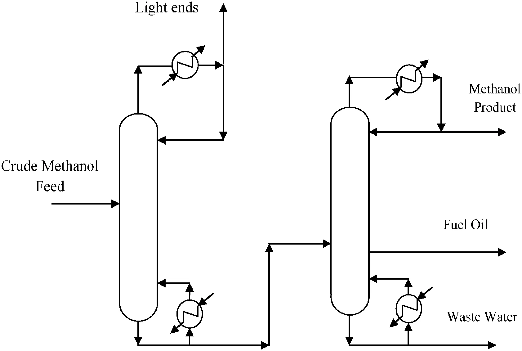
Fig.1.Schematic diagram of the traditionaltwo-column methanoldistillation.
In indirect-sequence,the heaviest component is removed first with the lighter components being removed in the following columns,leaving the separation of the lightest component for the last column[Fig.5(b)].In distributed sequences,the separations of the lightest and heaviest components are carried out in consecutive columns[Fig.5(c)][10].A Prefractionator sequence is an arrangement with partial thermal coupling using a partial condenser in the first column.This arrangementis preferred when the separation between the components is very dif ficult,or an intermediate component is high in composition[Fig.6(a)][11].In a Petlyuk column,flows of vapor and liquid are exchanged between the two columns.The first column,which is similar to Prefractionator,with no reboiler and condenser,provides the feeds to the second with part of it returning to the initialcolumn[Fig.6(b)].DWC is thermodynamically equivalent to the Petlyuk,with the advantage of allbeing con fined to only one column[13].With the presence of complex arrangements,there is a need to compare these with simple ones.In this paper,different arrangements for methanol distillation with or without heat integration using the Vmindiagram and rigorous simulation are compared with each other(Figs.5-7).This comparison is then used for the selection of the basic arrangement for methanol distillation.The basic arrangement willshow the development path of methanol distillation arrangements.The selected basic sequence is the optimalarrangement.Then the optimal arrangement thus obtained is compared with existing already developed arrangements for methanoldistillation(Figs.2-4).In this way,we can choose the development path for distillation arrangements,and analyze whether the new complex arrangements can replace current arrangements in methanoldistillation.It should be noted that today's complex arrangements,such as direct-sequence,which has been developed to 4-and 5-columns,may be further developed and optimized.Each sequence is simulated using a short cut method and Vminmethod which is then optimized using a cost function as criterion.The optimum conditions of alldifferent sequences were then compared on their financialmerits for the selection of the best.

Fig.2.Schematic diagram ofthree-column double-effect arrangement.
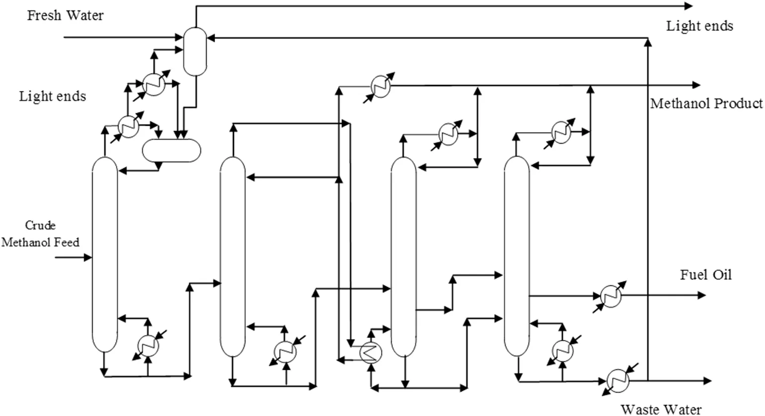
Fig.3.Schematic diagram of four-column arrangement.
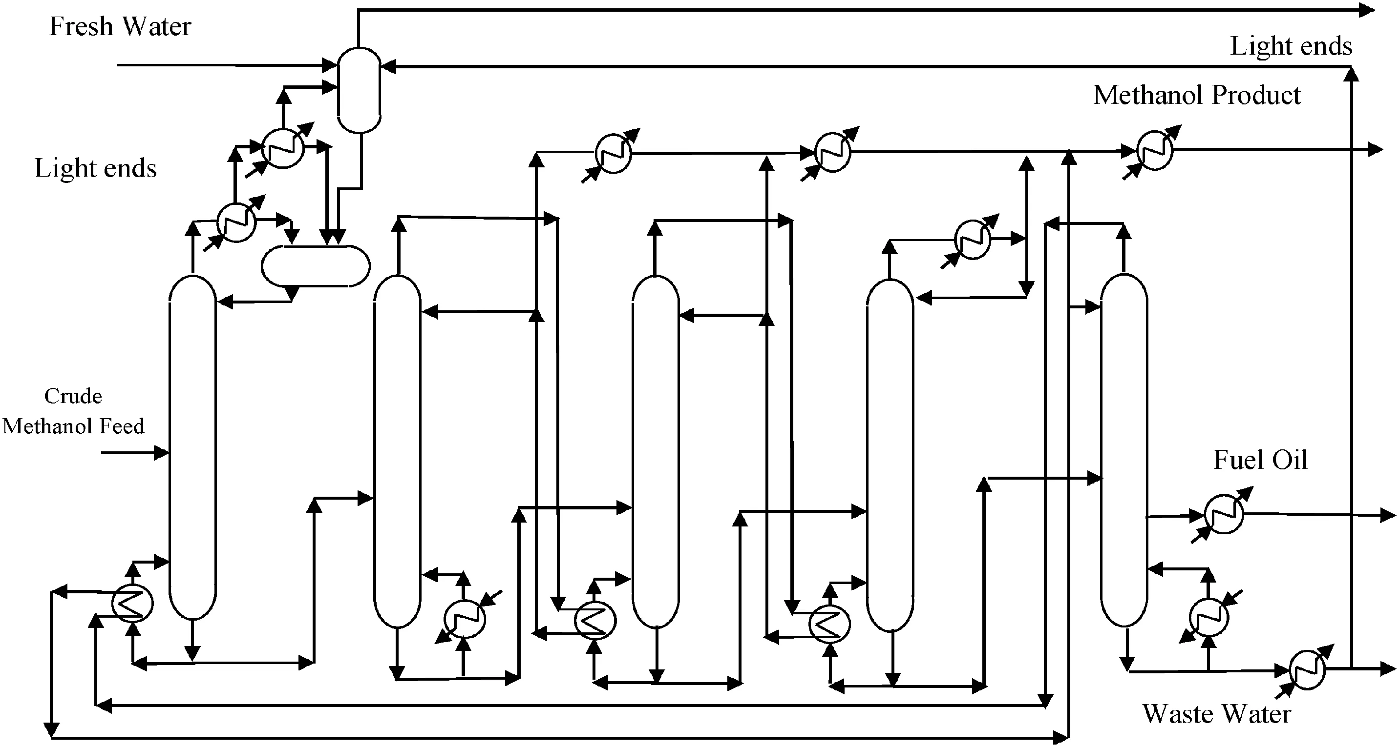
Fig.4.Schematic diagram of five-column arrangement.
2.Case Study
Here the case study,is the methanoldistillation unit.In doing so we are seeking an arrangement which can produce pure methanolby reducing energy consumption and costs.Initially using Vmindiagram method,different arrangements are compared in terms of energy consumption,before each is generated in a simulation environment.The mostef ficient arrangement in terms of energy consumption and economic costs is then selected and presented as the bestarrangementcapable ofproducing pure methanol.Table 1 presents the speci fications ofcrude methanol.

Fig.5.Simplex arrangements:direct-sequence arrangement(a),indirect-sequence arrangement(b),distributed sequences arrangement(c).
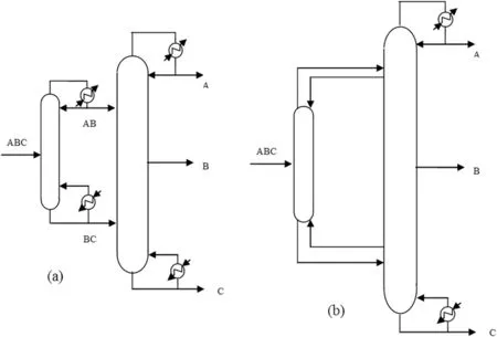
Fig.6.Complex arrangements:Prefractionator arrangement(a),Petlyuk arrangement(b).
Here,low boilers entailcompounds with a boiling point lower than methanol which are separated as light ends such as:dimethyl ether(DME),methyl formate,and acetone.High boilers are compounds with a boiling point higher than methanol and lower than water such as ethanol,propanol,1-butanol,butanol,2-pentanol,and octane.They are also separated as a lateral flow,with a heating value.The aim of methanol distillation is to produce AA degree methanol based on American Standards.The intended methanol needs to have special characteristics in order to reach AA degree.Table 2 presents these characteristics.
3.V min Diagram
Vmindiagram was for the firsttime presented by Halvorsen[14].Itis devised by means ofUnderwood equations,and is used for the idealand non-idealcompounds.Due to recent developments,the method of Vmindiagram,may be used as an engineering toolcapable of accurate and complete assessment of the potentialto minimize the energy required for distillation columns.Vmindiagram contains allthe information necessary to calculate the minimumenergy required,also showing internal flows needed for an optimaloperation of various arrangements for a multi-component feed with each of the products[15].This graph consists of information about intensity of vapor flow and distillation only based on the feed data.Multicomponent separation in this graph is only based on data feedstock,and it can be seen from the graph that the amount of energy required for any separation is only based on vapor flow to feed.The old column data is not required for the design of the new column[16].This simple graphicalmethod provides a direct insight into the proper separation behavior for different arrangements.Itmay be changed into an analyticalformand implemented within process simulators.In this paper,the results of the Vmindiagram based on Underwood and King equations[17]have been used as the initialdata required for the more accurate rigorous simulations.Halvorsen and Skogestad presentdetails of the analyticalmethod[18].As a simpli fication,the Vmindiagrams have been plotted based on only three components namely methanol,(B),as the main component,acetone,(A),as the heaviest component lighter than methanoland ethanol,(C),as the lightestcomponentheavier than methanol.Itis noted thatthis simpli fication of the components is to selectonly the basic arrangementamong different arrangements,then selected optimalarrangement compared with the current arrangements ofmethanoldistillation.This compares to is that the author to see whether the selected optimalarrangement ability to compete with the current arrangements ofmethanoldistillation?K value and relative volatility of key components to the heavier ones are shown in Table 3.The optimum operating conditions were set at the minimum energy required to produce products with a fixed purity.The Vminvalues obtained using the Underwood and King equations were then plotted.Method to obtain the Vmindiagram and how to use it is similar to work for Engelien and Skogestad in 2004[17].Results for Vmindiagram are used as a graphicaltoolfor the rapid determination of the multi-effect distillation used in this work.The data needed to plot the Vmindiagram are,feed compositions,mole fraction,and the relative volatility of the components.Recovery values for key components,and the vapor and distillate flow rates are obtained from Vmindiagram,and the minimum number of trays and feed tray location are obtained from the short-cut method.The number oftrays can be considered 4Nminin the rigorous simulation as proposed by Halvorsen[14].
Vmindiagram can also be used to find the minimum vapor flow of multi-effectarrangements with heatintegration(Fig.7).This is presented by Fig.8 for the multi-effect arrangements.The mentioned graph here is used for the analysis ofa mixture containing acetone,methanol and ethanol.
Here,relative volatility is taken into account at two different pressures.As the diagram indicates,the lowest vapor flow rate exists in the Prefractionator arrangement indicating a less energy consumption for this arrangement.Values obtained can be used as the initial estimate ofrigorous simulation under ef ficientconditions[19].Itshould be noted that in this diagram Direct,Indirect,Prefractionator arrangements with heat integration and Petlyuk arrangement are compared to each other,among which the Prefractionator has the minimum vapor flow rate.
Here,itis probable that Prefractionator,due to its lower vapor flow rate,can be selected as the ef ficient arrangement from among different alternatives(Table 4).The highest energy savings(minimum vapor flow rate)for the Prefractionator with integration occur because there is a high concentration of the middle component(methanol)and as well as smallamounts of the light component(acetone)in the feed[15].There is generally a large difference between the Prefractionator with integration arrangement and the Petlyuk arrangement,which is the best non-integrated arrangement.Results obtained from Vmindiagram is used for simulating alternative arrangements under optimum conditions to select the most ef ficient arrangement more precisely by taking energy costs into consideration.
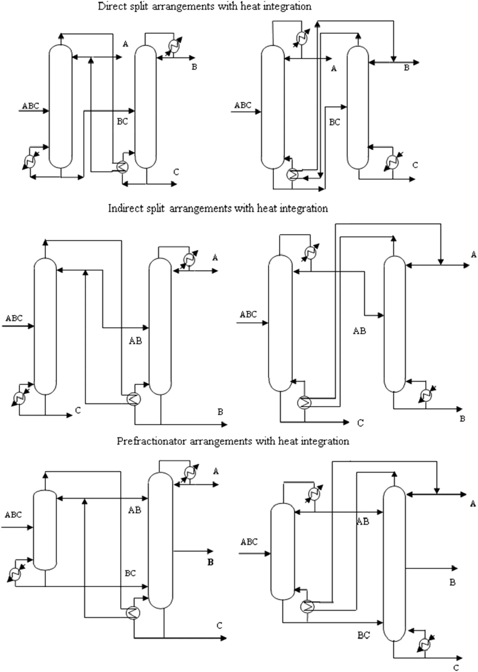
Fig.7.Multi-effect arrangements with heat integration.
4.Simulation of Different Arrangements Under Steady-state Conditions
Vmindiagram is initially used to examine allpossible modes ofcolumn arrangements,followed by the Short cut model to provide the total number of trays as well as the feed tray location,eventually using the HYSIMInside-Out method in a simulation environment to carry out the rigorous simulations.The NRTL modelhas been used for thermodynamic predictions.A quasi Newton method is then used to optimize the pro fit function for each simulation.
Hot utility used is saturated steam at 0.5 MPa pressure.Inlet and outlet temperatures of water cooling in condensers are 30 and 40°C,respectively.According to American Standard AA grade methanol must have 99.8%puri fication which is the fixed speci fication used through.The methanol composition in waste water should also not exceed 0.005 wt%.
To optimize arrangements suggested by pro fit function,the utility,feed and product costs should be determined.Table 5[20]and Table 6[21,22]show the utility,feed and productcosts,respectively.Procedures concerning with evaluation of costs of installation and commissioning of columns and exchangers are provided in Appendix A.
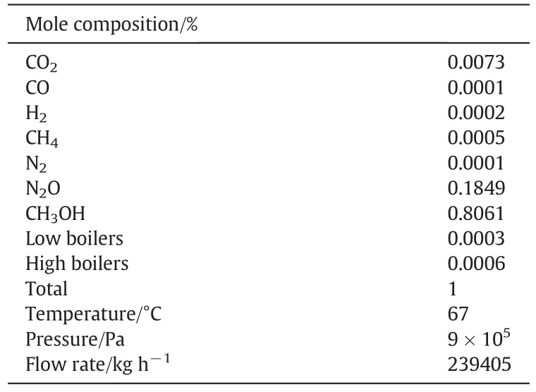
Table 1 Crude methanolspeci fications
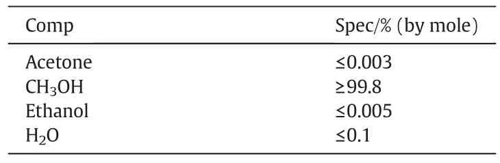
Table 2 Characteristics of AA degree methanol
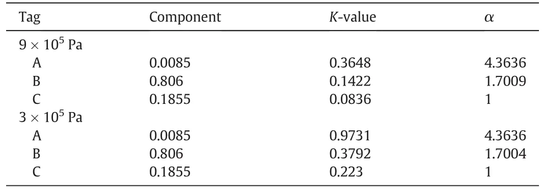
Table 3 Values of relative volatility ofkey components in two different pressures
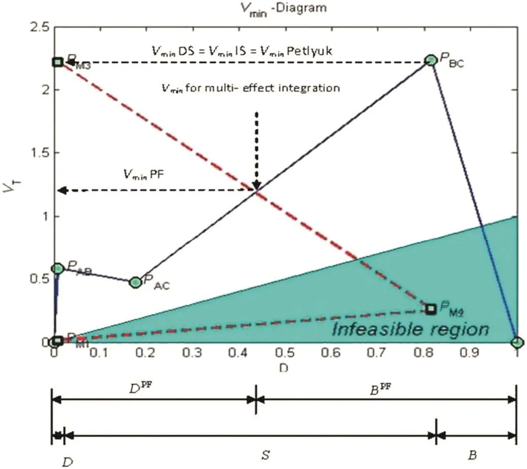
Fig.8.V min diagram of multi-effect arrangements with heat integration.
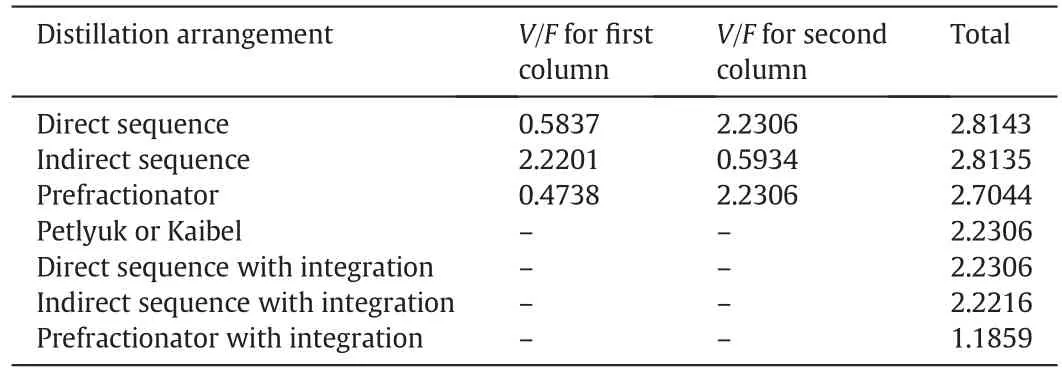
Table 4 Energy required for different arrangements
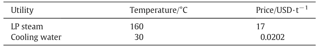
Table 5 Price ofutility units
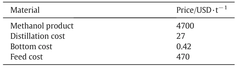
Table 6 Price offeed materials and products
5.Results and Discussions
5.1.Analysis ofenergy consumption
Tables 7,8 and 9 show the operating conditions and calculated results of every column for non-heat integration,heat integration and currentarrangements used in methanoldistillation.
It should be noted that the current arrangements described in Table 9,are developed in direct sequence arrangement.Here the Vmindiagram is used for the selected arrangement with minimum energy consumption.The simple and complex arrangements are compared in Tables 7 and 8.The results obtained here are compared with the conventionalarrangements in Table 9.
As the results show,directcolumn sequence arrangementcompared to arrangements without heat integration has the lowest energy consumption value of 138.67 MW,while among heat integrated arrangements indirect split with integration,which produces less methanol,has the lowest energy consumption value of 113.6 MW.In an overall comparison among all arrangements it appears that heat integrated Prefractionator with an energy consumption value of 117.5 MWand methanolproduction of211600 kg·h-1is the mostfavorable.As the results obtained from simulation in Table 9 show,among conventional proposed arrangements of methanol distillation,fivecolumn arrangement(which has not been applied industrially),with 75.87 MWhas the lowest energy consumption.
Therefore,Prefractionator with heatintegration is the only arrangementdemonstrating some advantages over allother arrangements proposed so far,in terms ofenergy consumption,methanolproduction etc.What is obtained from Vmindiagram for multi-effect arrangements also shows that among alternative arrangements of methanoldistillation,Prefractionator has the lowest Vmin/F,that is the lowest energy consumption among alternative arrangements.This arrangement oflower energy consumption has been compared with simple and complex arrangements.Although when compared to the five-column arrangement it utilizes more energy,as more methanolis also produced from this method,it is more economically bene ficial.It may also be added that there is still potential for further development of the arrangementproposed here.But,arrangements should be compared to each other on the basis of energy consumption as wellas economic costs so that a more precise comparison for ef ficient selection is made.

Table 8 Calculated results of methanoldistillation ofevery column in arrangements with integration
5.2.Temperature difference ofheat transfer
Tables 10 and 11 show the temperature difference on both sides of condenser/reboiler for every double-effect arrangement and for conventional arrangements of methanol distillation respectively.As Table 10 shows,temperature difference in indirectsplitwith integration is higher than that of other arrangements.It is even higher than the temperature difference on both sides of each condenser/re-boiler for conventionalarrangements shown in Table 11.
As allthe temperature differences are higher than 9°C which are appropriate for the required heat transfer and therefore support the possibilities ofnew processes.
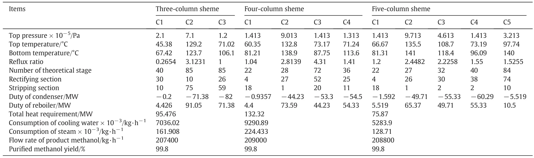
Table 9 Calculated results of methanoldistillation ofevery column in current arrangements
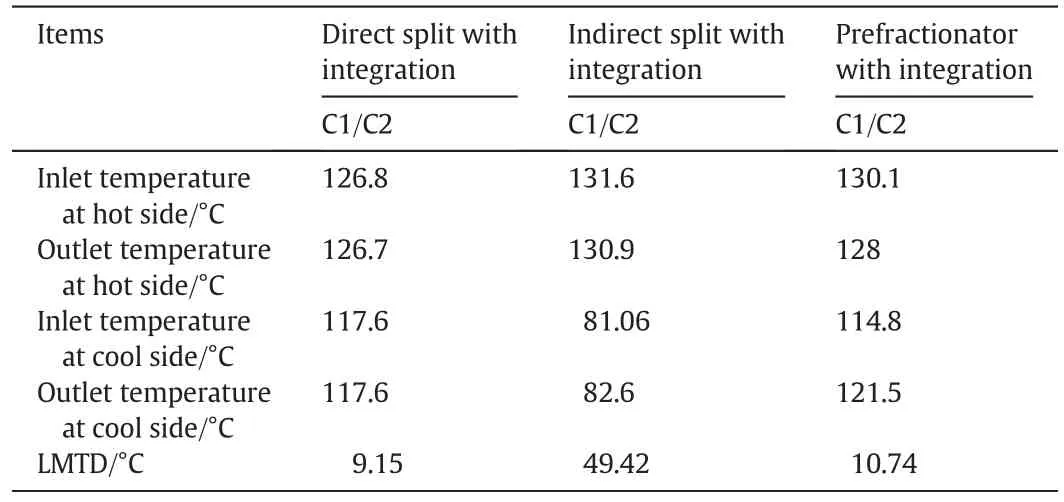
Table 10 Temperature difference on both sides of condenser/reboiler for double-effect distillation

Table 11 Temperature differences on both sides ofcondenser/reboiler forcurrentmethanoldistillation arrangements
Table 12 shows the temperature difference from every double-effect arrangement,which uses the saturated steam at 0.5 MPa as the heat resource.
One of the flaws of temperature difference reduction in reboiler for various arrangements is the increase in heattransfer levelofthat arrangement.The latter leads to increase in capital cost of the arrangement.C1 column in double-effect arrangements is the high pressure column.As Table 12 shows,temperature difference ofindirect split with integration is lower than that ofother arrangements.That is,heat transfer levelof the arrangement is increased.In current methanol distillation arrangements,C2 is the high pressure column.
According to Table 13,compared to other arrangements,fivecolumn one has the lowest temperature difference,therefore one ofits defects is the increase in heat transfer leveland consequently,rise in capitalcost.
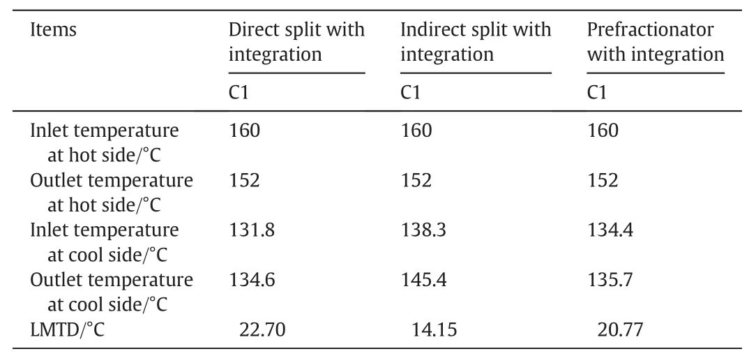
Table 12 Temperature differences on both sides of vapor-heated reboilers in double-effect arrangements
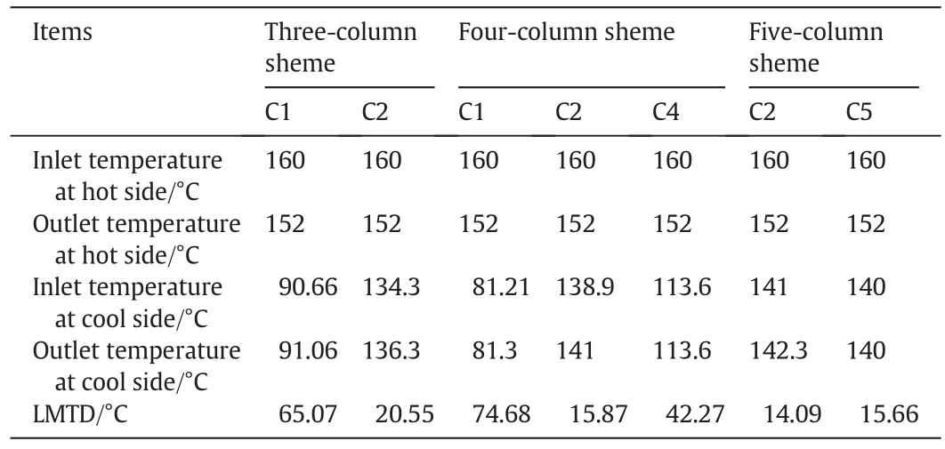
Table 13 Temperature difference on both sides of steam-heated reboilers in current methanol arrangements
5.3.Technicaleconomic analysis
Tables 14,15 and 16 show the economic calculations regarding alternative methanoldistillation arrangements.In these tables,pro fit and totalpro fit are calculated as:
Here,the basis ofarrangementcomparison for technicaleconomic analysis is two-column direct column sequence arrangement,against which allother arrangements with or without heat integration and also conventional methanol distillation arrangements are compared.As it is shown in the tables,although Prefractionator with heat integration,whose bene fit increase is 4.79%,compared to the basic arrangement is the only one capable of competing with conventional arrangements of methanol distillation,three-column,four-column and five-column arrangements have bene fit increases by 3.61%,3.55%and 3.46%,respectively.In fact,the pro fitincrease depends on reducing the costand increasing the income.Here,itcan be seen that operating costs of Prefractionator with heat integration is low,compared to two and three-column arrangements,but higher than that of four and five-column arrangements.Increase in income obtained from production of pure product leads to the increase in Prefractionator with heat integration pro fit.This arrangement with heat integration saved the operating costs by 28.03%and increased the capitalcost by 8.87%.The degree of saving of operating costs in Prefractionator with heat Integration is almost equalto that of four-column and more than that ofthree-column arrangements.Compared to five-column arrangement,Prefractionator has lower saving ofoperating costs.It is obvious that due to the number of columns in conventionalmethanoldistillation arrangements,these arrangements have higher capitalcost compared to Prefractionator.
As it is shown,the value of saving for three-column,four-column and five column arrangements is 27.78%,28.85 and 29.28,respectively.According to results,the operating cost is two orders of magnitude larger than capital costs.Consequently,it can be said that as far as possible in arrangement designs,the number ofheat integrations and heat exchange volume should be increased because the degree of operating costs reduction is far higher compared to degree of increase in capitalcosts.So,according to feed compositions,those arrangements should be preferred which provide more heat integration potentials.It is also apparently clear from the results that water cooling costs of condensers is one order of magnitude smaller than steam costs for reboilers and hence more attention should be paid to temperature reduction and reboilers'heat consumption in the columns optimization process.
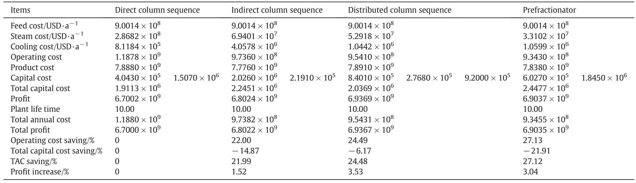
Table 14 Results ofeconomic costs ofmethanoldistillation alternative arrangements without heat integration
According to other results,it may be concluded that in order for the capitalcostto reduce,itis betterto keep the minimum temperature difference in condensers of columns,to enable the use of cooler hot utility.
Fig.9 shows the comparison of calculated values of total pro fit for four arrangements which are normalized and obtained according to the largest value.As the Prefractionator with integration is a two-column arrangement;according to the comparison with a conventionaltwo column process provided in Table 15 has a lower operating cost and thus is more pro fitable.Hence compared to the base state,this arrangement is better than the other arrangements.In comparison to the Prefractionator with the conventionalthree-column distillation ofmethanol,ithas a lower operating cost,more productincome,higher capital cost,lower total annual cost and hence is more pro fitable.When comparing the proposed Prefractionator arrangement with the conventional4 and 5 column processes,it has a higher operating cost,more product income,lower capitalcost,higher totalannualcost and is therefore more pro fitable.The reason behind the presentation of 4 and 5 column arrangements is to reduce costs and methanolwaste at the same time.The propose Prefractionator arrangement with heat integration also has potentials for more development to further reduce costs and methanolwastage.Tables 15 and 16 show that total capital cost of Prefractionator arrangement with heat integration(2.0974×10⁶)is lower than of three-column(1.7302×10⁷),fourcolumn(2.7800×10⁶)and five-column(2.4646×10⁶).Not only is the operating cost of Prefractionator with heat integration higher than those of four-and five-column arrangements,but also the amount of product cost is also higher than those of the mentioned arrangements.
It should be noted however,that totalcapitalcost of Prefractionator is lower than that of four-and five-column arrangements leading to higher totalpro fit of Prefractionator.Considering life time of 1,10 and 20 years,this comparison is shown in Fig.8 for allfour arrangements.Itis obvious thatthe value oftotalpro fitof Prefractionator with heatintegration is higher than the value ofother arrangements.So,it can be said that Prefractionator with heat integration is the most economical arrangement for methanoldistillation.
6.Conclusions
(1)A comparative study of different arrangements for methanol distillation process is presented in this paper.
(2)Shortcut equation for minimum vapor flow rate and Vmindiagram in distillation systems,presents an appropriate target for comparing energy consumption in different arrangements.
(3)Prefractionator arrangement has the lowest Vmin/F,that is the lowest energy consumption among alternative arrangements.Also thisarrangementhas an appropriate temperature difference for heat transfer in condenser and reboiler.
(4)It has been shown that the Prefractionator with heat integration arrangement exhibits signi ficant bene fit increase compared to conventionalarrangements of methanoldistillation.
(5)Utilization of an economic equation demonstrating the pro fit instead of total annual cost leads not only to a more flexible combination ofoperating,capital,feed costs and productbene fits in our equations,butalso better decisions are made for selecting ef ficient arrangements.
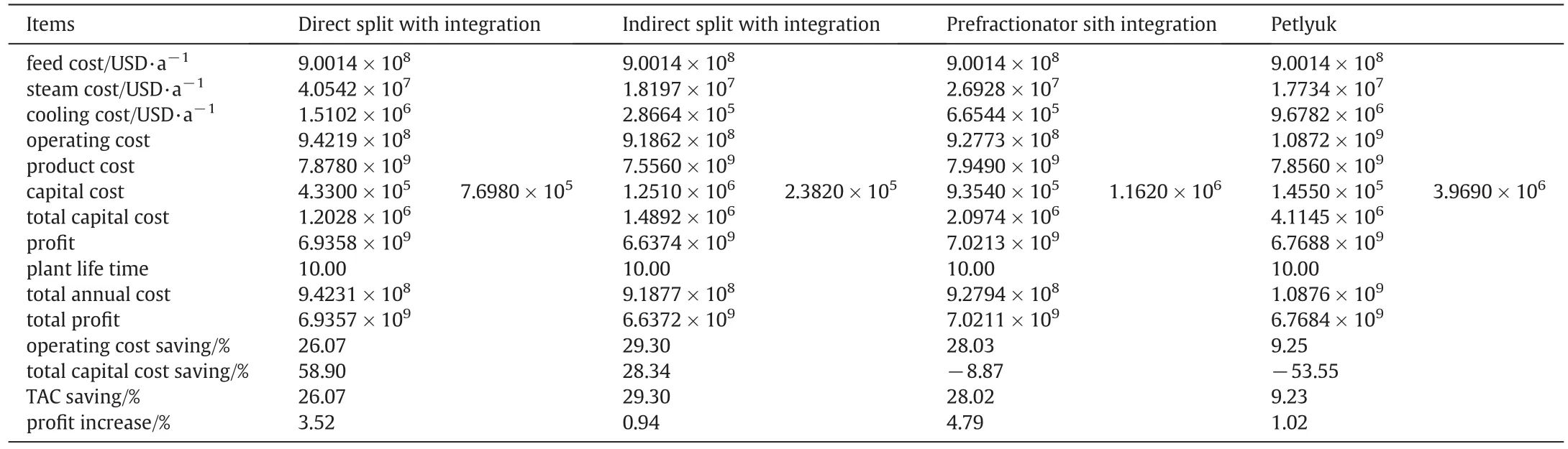
Table 15 Results ofeconomic costs ofmethanoldistillation alternative arrangements with heat integration
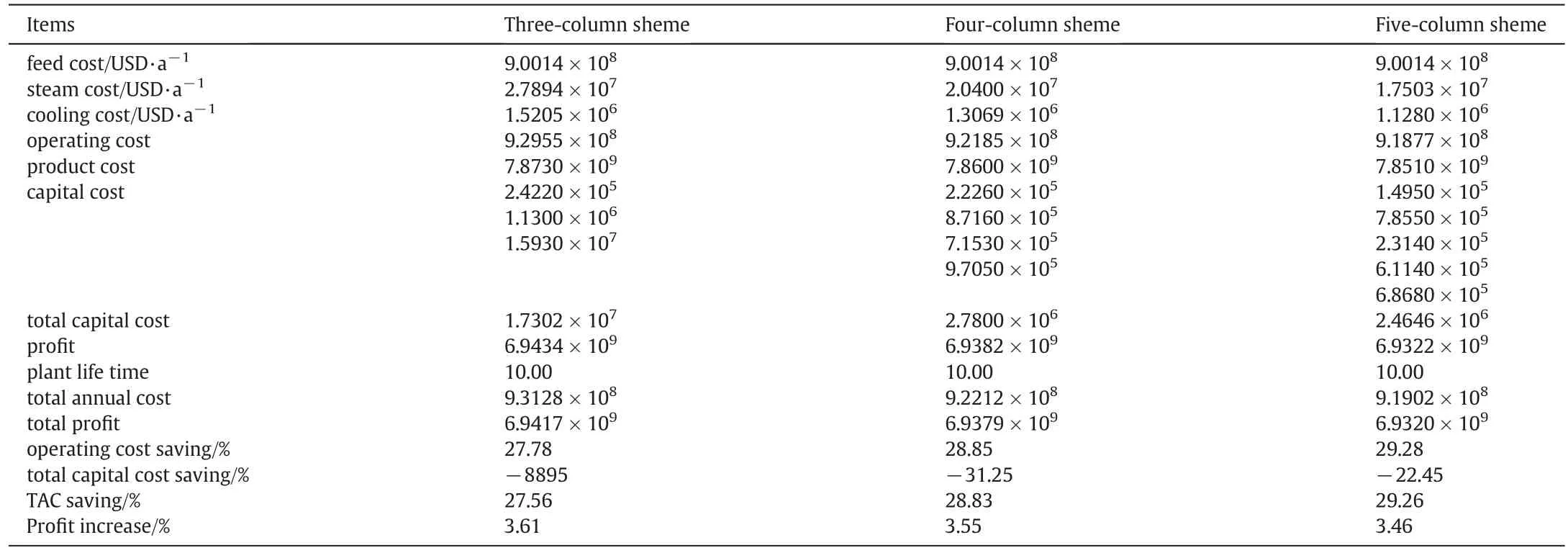
Table 16 Results ofeconomic costs of current methanoldistillation arrangements
Nomenclature
Appendix A
Here,pro fit is calculated through subtraction of Income and costs:

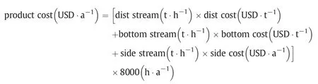
Income obtained from product sale is calculated by:
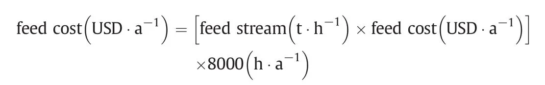
Cost ofinlet feed to arrangements is calculated through:
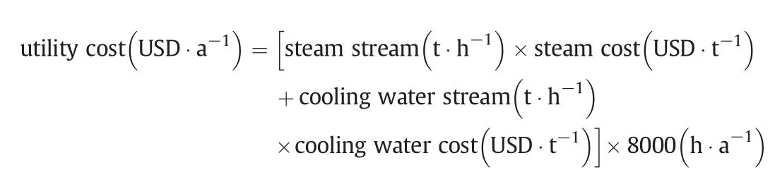
Utility costis obtained by this equation:
In many ofarticles,for optimization the minimization oftotalannual cost is used,which is calculated as such:
Number 10 in above formula is considered with plant lifetime.Calculation ofarrangements costs includes parts below:
1.Capitalcost
(1)Cost of column purchase,which it itself involves cost of column body,tray and installation.
(2)Costsconcerning purchase and installation ofheatexchangers including condensers and reboilers.
2.Operating cost.
3.Costs regarding utility parts.
Calculation ofcost ofcolumn purchase requires column height and diameter.The latter is obtained by simulator software and the former is a function ofnumber oftrays.For a certain number oftrays the theory is identi fied.That is,after running,the software determines the diameter of distillation column having Valve tray and Weir height of about 50.8 mm.For estimating real number of trays,column total ef ficiency is calculated by:
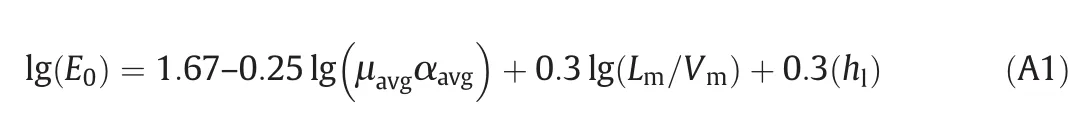
In this equation,μavgis the average feed viscosity,which is calculated by totalmultiplication ofmole feed components fraction atcomponents viscosity.Αavgis the relative volatility ofaverage key feed components.Lm/Vmdiffer in rectifying and stripping parts whose average is calculated and used in the following formula:

Considering distance between trays being 0.6 and disengagement being 6 m,column heightis calculated by:

When tray stack height equals:

Costs ofdistillation columns(assuming that carbon steelmaterialis used in column production)can be calculated through below formula,which is updated by CEPCI(Chemical Engineering Plant Cost Index).Cost concerning installation ofcolumn body:


Fig.9.Values of totalpro fit for four arrangements.
Ifthe design pressure is more than 345 kPa,a correction factor will be used:

Costs concerning column tray installation:

Totalcolumn cost equals total column body installation cost plus column tray installation cost which can be obtained through following equations.According to its heattransfer level,exchangercostis calculated by this equation:

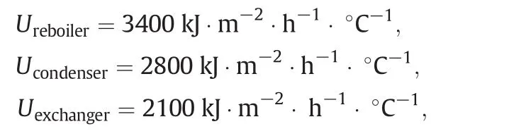
In the above equation,A represents heat transfer level,Q exchanger heatload,U the average heattransfercoef ficient,ΔTLMlogarithmic average temperature.Heat transfer coef ficients[21]for this system are calculated by:
Assuming that exchangers are shell and tube,floating head and carbon steel,exchanger cost willbe obtained by:

Above relationship is true for 18.6<A<464.5 and pressure higher than 1034.2 kPa.Below equation leads to the utility costs:

Here W is the wateror steam flow in terms oft·h-1(ton per hour),C represents water or steam price in terms of USD·t-1,Hyis the total work hour in a year equaling 8000 h per year.
Allthe costs are based on mid-1968 and mid-2013 updates,which itselfis based on CEPCIcost index[23].
[1]K.Engelien,S.Skogestad,Selecting appropriate controlvariables for a heat integrated distillation system with prefractionator,Comput.Chem.Eng.28(2004)683–691.
[2]R.Agrawal,Separations:Perspective of a process developer/designer,AIChE J.47(2001)967–971.
[3]A.K.Jana,Heat integrated distillation operation,Appl.Energy 87(2010)1477–1494.
[4]J.Wu,L.Chen,Simulation of novelprocess of distillation with heat integration and water integration for puri fication of synthetic methanol,J.Chem.Ind.Eng.(China)56(2005)477–481(in Chinese).
[5]Z.C.Zhou,J.Wu,Novelpuri fication process ofsynthetic methanolwith fullintegration ofheat and water,J.Chem.Ind.Eng.(China)58(2007)3210–3214(in Chinese).
[6]B.Z.Liu,Y.C.Zhang,P.Chen,K.J.Yao,Research on energy-saving process ofmethanol distillation,Chem.Ind.Eng.Prog.(China)26(2007)739–742(in Chinese).
[7]R.A.Meyers,Handbook of synfuels technology,McGraw-Hill,New York,1984.
[8]Y.Z.Chu,L.P.Qin,S.L.Wang,Y.Huang,S.P.Zhou,Optimum design ofmethanol distillation process and columns,Chem.Ind.Eng.Prog.(China)27(2008)1659–1662(in Chinese).
[9]J.Zhang,S.Liang,X.Feng,A novelmulti-effect methanoldistillation process,Chem.Eng.Process.49(2010)1031–1037.
[10]R.Premkumar,Retro fitting industrial,conventional column systems to Petlyuk/Divided Wallcolumns,A thesis submitted for the degree of master ofengineering,Department of Chemical and Bio-molecular Engineering,National University of Singapore,2007.
[11]H.Seki,M.Shamsuzzoha,Process design and control of dividing wall columns,KFUPM Dhahran,Saudi Arabia,2012 25–26.
[12]I.Dejanovic,L.Matijasevic,I.J.Halvorsen,S.Skogestad,H.Jansen,B.Kaibel,Z.Olujic,Designing four-product dividing wallcolumns for separation of a multicomponent aromatics mixture,Chem.Eng.Res.Des.89(2011)1155–1167.
[13]I.J.Halvorsen,S.Skogestad,Energy ef ficient distillation,J.Nat.Gas Sci.Eng.(2011)1–10.
[14]I.J.Halvorsen,Minimum energy requirements in complex distillation arrangements NTNU PhD Thesis 2001.
[15]I.J.Halvorsen,S.Skogestad,Minimum energy consumption in multi-component distillation.3.More than three products and generalized Petlyuk arrangements,Ind.Eng.Chem.Res.42(2003)616–629.
[16]I.J.Halvorsen,S.Skogestad,Minimum energy consumption in multi-component distillation.2.Three-product Petlyuk arrangements,Ind.Eng.Chem.Res.42(2003)605–615.
[17]H.K.Engelien,S.Skogestad,GraphicalVisualisation ofMinimum Energy Requirements for Multi-Effect Distillation Arrangements,2003 submitted to the AIChE Journal,(February 2003).
[18]I.J.Halvorsen,S.Skogestad,Minimum energy for the four-product Kaibel column,AIChE annual meeting,AIChE,San Fransisco,Paper 216d,2006.
[19]I.Dejanovic,L.Matijasevic,Z.Olujic,An effective method for establishing the stage and re flux requirement of three-product Dividing Wall columns,Chem.Biochem.Eng.Q.25(2)(2011)147–157.
[20]S.Lee,N.V.D.Long,M.Lee,Design and optimization ofnaturalgas liquefaction and recovery processes for offshore floating lique fied natural gas plants,Ind.Eng.Chem.Res.51(2012)10021–10030.
[21]S.k.Almeland,K.A.Meland,D.G.Edvardsen,S.Skogestad,M.Panahi,Process design and economical assessment of a methanol plant,NTNU Norwegian University of Science and Technololy,Faculty of Natural Sciences and Technology,Department of Chemical Engineering,2009.
[22]E.Rev,M.Emtir,Z.Szitkai,P.Mizsey,Z.Fonyo,Energy saving of integrated and coupled distillation systems,Comput.Chem.Eng.25(2001)119–140.
[23]http://www.chemengonline.com/pci.
 Chinese Journal of Chemical Engineering2016年9期
- Chinese Journal of Chemical Engineering的其它文章
- Heat transfer ofnano fluidics in hydrophilic pores:Insights from molecular dynamics simulations☆
- Numericalsimulation ofstirred tanks using a hybrid immersed-boundary method☆
- Numericalsimulation ofmicromixing effect on the reactive flow in a co-rotating twin screw extruder☆
- Coalescence behaviour ofwater droplets in water-oilinterface under pulsatile electric fields
- Effects of Sn residue on the high temperature stability of the H2-permeable palladium membranes prepared by electroless plating on Al2O3 substrate after SnCl2–PdCl2 process:A case study☆
- Application ofdiffusive transport modelfor better insight into retardation mechanisms involved in ion-imprinted membrane transport