Design and test of clamping and conveying device for recycling agricultural residual plastic film
2017-01-09 05:31LiTianwenDuanWenxianWangJikuiLiYangBiXinshengGongHeheDingShuangshuang
农业工程学报 2016年24期
Li Tianwen, Duan Wenxian, Wang Jikui, Li Yang, Bi Xinsheng, Gong Hehe, Ding Shuangshuang
Design and test of clamping and conveying device for recycling agricultural residual plastic film
Li Tianwen, Duan Wenxian, Wang Jikui※, Li Yang, Bi Xinsheng, Gong Hehe, Ding Shuangshuang
(,832003,)
The machines currently used to recycle residual plastic film operate by picking up the plastic film using an arc-shaped spring-finger and removing the plastic film with a rotary roller. This method is problematic because it has a lower recycling rate. The film is also easily to wind around the operating parts of the mechanism which would lead the film to be difficult to remove. According to the characteristics of film, a clamping and conveying device for removing agricultural residual plastic film pneumatically has been designed. The device is mainly composed of a film-pickup mechanism, a clamping-conveying mechanism and a film pneumatic removal mechanism. The structure, dimensions and the operating parameters of these mechanisms were determined through discussion and analysis. The materials of the scraper and the conveying belt were determined. The position of the scraper component relative to the conveying belts was also obtained by calculation. The process of picking up the film and raising it with a shovel was analyzed. The pressure force acting on the clamped film (applied by one of the scrapers) was theoretically analyzed and tested. In order to convey the agricultural residual plastic film (ARPF), it was found that the minimum clamping force was 4.58 N. Field experiments showed that the film could be scooped up from the ground with shovels and successfully fed into the clamping-conveying mechanism. The film could be clamped stably throughout the film conveying process and removed smoothly by the pneumatic removal mechanism, which prevented the film from adhering to, or winding around, the parts of the mechanism. When the operating speed of prototype was 5-5.5 km/h, the results of the field experiment indicated that the average recycling rate of the ARPF was 92.5% and the average removal rate of the ARPF reached 97.8%. The results of this research may provide references for the development of new machines to recycle residual plastic film.
agricultural machinery; design; recycling; agricultural residual plastic film; device; clamping-conveying; airflows film removal
0 Introduction
The agricultural plastic film mulching technology that is widely used in China has the advantages of promoting early-ripening, high-yield, fine-quality and high-efficiency crops[1-3]. By 2014, the technology was being used for more than 20 kinds of crops—including tomatoes, cotton and sugar beets —over an area of 3.13 million hm2.In some areas, such as in Xinjiang, this technology is used for more than 75% of the total sown area of crops[4-5]. However, due to the non-degradable organic polymer compound of the plastic film that is used, it is extremely difficult to cause this film to decompose under natural conditions. This presents a serious potential crisis for the agricultural ecological environment. The agricultural residual plastic film (ARPF) in the soil layer hinders the absorption of water and nutrients by the crop roots andreduces the yield and quality of the crops[6-8].For example, on a particular cotton plantation in Xinjiang, the ARPF amount in the soil layer has reached a level of 253.2 kg/hm2; this isfour or five times the national average[9-10]. Thus, it seems that ARPF pollution is more serious in areas with cotton plantations. Now, the recycling of ARPF has become an urgent problem for the sustainable development of agriculture in China[11-14].
Mechanical ARPF recycling is an effective way to solve farmland ARPF pollution. After many years of research, many kinds of ARPF recycling machines have been designed. Based on their structure and operating principles, the machines currently used for recycling ARPF may be classified into three types; namely, dense spring-tooth row, spring-finger cylinder pickups and chain-tooth rake[15-18]. Each method picks up the ARPF with elastic teeth. However, the ARPF in the fields is mixed with crop roots, stubble and soil, which often causes the ARPF to slip off of the collecting teeth of the machines[19-20]. This means that the amount of ARPF that is effectively recycled is low. In addition, ARPF is light, soft and often coated with some type of adhesive; all of these factors often cause it to wind around the collecting parts and removing rollers of the machines[21-25]. This interferes with effective ARPF collection. Because of the lack of efficient machines for ARPF recycling, ARPF recycling technology has not been widely adopted in China, and the plastic film recycling rate remains low. Thus, the pollution resulting from agricultural plastic film is exacerbated year by year[26-30].
When cotton is harvested, the sheets of ARPF in the fields are exposed; therefore, this is a good time to collect the ARPF from the fields. Based on the clamping principle, a clamping and conveying film recycling (CCFR) device was designed for collecting ARPF, and then removing it from the device pneumatically. This paper presents this CCFR device and process. The CCFR device was shown to successfully accomplish the process of picking up, clamping and conveying the film, and then successfully pneumatically removing it. Field test results showed that ARPF of various sizes and weights could be successfully recycled using the device, and the pneumatic film removal process could successfully keep the ARPF from winding around the collecting parts. The results of the study could provide a significant reference for the design of new machines for ARPF recycling.
1 Structure and operating principle ofCCFR device
1.1 Structure of CCFR device
The 4JM-1 cotton stalk chopping and film collecting machine mainly consists of a stalk smashing device, a stalk conveying device, a CCFR device, power transmission systems, a frame and ground wheels[31]. The schematic diagram of the machine is shown in Fig.1. The CCFR device is located behind the stalk smashing device. The CCFR device is composed of a shovel, a clamping and conveying mechanism and a pneumatic film removing mechanism. The clamping-conveying mechanism consists of a scraper component and a conveying belt component.
1.2 Operating principle of CCFR device
The operating principle of the 4JM-1 cotton stalk chopping and film collecting machine is as follows. First, the cotton stalk is chopped by the straw smashing device and carried to the rear of the machine by the stalk conveying device. Meanwhile, the film is scooped up from the ground by the shovels and scraped upwards onto the conveying belt by the rotating scraper component. With the scraper component and the belt rotating in opposite directions at an equal linear velocity, the ARPF is clamped and conveyed by the scraper and the belt. Finally, the ARPF is blown off and down into the box by the action of the film removing mechanism as the film is carried to the upperside of the plastic film box.
a. Main view
b. Plan view
1.Power transmission system 2.Stalk smashing device 3.Fan 4.Straw conveying device 5.Clamping mechanism 6.Film box 7.Film removing mechanism 8. Ground wheel 9.Conveying mechanism 10.Shovel
Fig.1 Sketch of 4JM-1 cotton stalk chopping and film collecting machine
1.3 Main technical parameters
The main technical parameters of CCFR device were shown in Table 1.
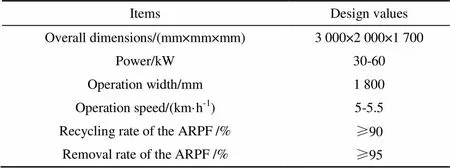
Table 1 Main technical parameters of CCFR device
2 Design of main components
2.1 Film shovel
The shovel is applied to scoop up the ARPF and lift it to a certain height from the ground. In this way, the ARPF can be clampedsuccessfully bythe clamping and conveying mechanism. Because the film is soft and flimsy (it tears easily), the shovel must get into the soil and scoop up a certain amount of the soil layer, and as the soil layer moves up the shovel surface, the ARPF lying on the soil layer may be lifted up off the ground.
The main factors affecting the penetration ability of the shovel include the sharpness of the shovel blade, the width of the shovel blade and the penetrating angle of the shovel. A shovel with a sharp blade can easily get into the soil. When the penetrating angle is smaller, the shovel does not enter deep into the soil, but the ARPF moves up along the surface of the shovel blade easily. When the shovel is wider, less of the film is torn, but the shovel does not enter the soil very deeply at all, and the ARPF often falls off of the shovel blade on uneven ground. The soil under the plastic film has a certain humidity and low strength after the crops are harvested, so the penetrating angle of the shovel should be small for a shovel with a sharp blade. In order to ensure that the ARPF is scraped off ground, the penetration depth of the shovel should be 30-50 mm. Then, the penetrating angleof the shovel is determined to be 25° by field experiments. Considering the conditions of the field surface and the effects of ARPF recycling, the width of the shovelis 80 mm. The shovel assembly was shown in Fig.2.
a. Main view
b. Plan view
1.Shovel 2.Driven pulley 3.Rod 4.Supporting wheels 5.Conveying belt 6.Supporting plate 7.Driving pulley
Note:is the installation angle of the shovel, (°);is the spacing between two shovels ,mm;is the width of the shovel, mm.
Fig.2 Sketch of shovel and conveying belt component
In addition, due to the fragility of the ARPF and the limited film lifting ability of a single shovel, multiple shovels must be arranged side by side. The distance between two shovels is determined by the strength of the ARPF and the quantity of stalk andsoil particles mixed in with the ARPF on the ground. When the distance between two shovel blades is too small, less film is left on the ground, but the shovels are easily blocked by clods and stalks. Through field experiments, the spacingbetween two shovels was set as 350 mm. Considering the factors of the CCFR device structure, the shovel was installed on the end of two rods.
2.2 Clamping and conveying
The function of the clamping and conveying mechanism is to clamp and convey the ARPF from the surface of the shovel up to the pneumatic film removing mechanism. The scraper component is on the upper side of the conveying belt.
2.2.1 Scraper component
The scraper component is composed of a scraper, a traction chain, a driving sprocket and a driven sprocket. The scrapers fixed on the outer side of the traction chain can be driven along the conveying belt. The structure of the scraper component is shown in Fig.3. The scraper is made of material with good elasticity and toughness to maintain a continuous stable pressure on conveying belts during operation. The length and width of the scraper are 1 800 mm and 80 mm respectively. The spacing between adjacent scrapers is 300 mm.
Because the haulage chain and the scraper have a certain softness property, the scrapers will deform and incline when it is pressed on conveying belts. When the spacingbetween haulage chains and conveying belts becomes smaller, the inclination and deformation of the scrapers will be greater. And the pressure acted on the conveying belts by scrapers will be greater. The clamping force can be changed by adjusting the spacingon the condition of the haulage chain being tension. When the CCFR device is operating, the underside of haulage chains are tensioned, the inclination angle of scrapers decreases, and the deformation of scrapers increases. In the way, the clamping force between the scrapers and the conveying belts can be guaranteed.
2.2.2 Conveying belt component
The conveying belt component is composed of a conveying belt, a driving pulley, a driven pulley, a support plate and a shield. To prevent litter that is mixed in with the ARPF from being collected, the conveying belt should not be too wide. Therefore, the B1550 type V-belt was used. The structure of the conveying belt component is shown in Fig.2.
Due to flexibility of the V-belt, the conveying belt can become deformed under the action of the scraper when it is operating, which causes the film clamping force to fluctuate when the scraper is in motion. Therefore, supporting wheels are necessary to strengthen the rigidity of the conveying belt. The supporting wheels are underneath the conveying belt. The conveying belt is composed of the supporting plate, wheels and pin shafts. The supporting wheels are installed on the pin shafts, which are fixed between the two supporting plates by bolts. When the conveying belt runs between driving pulleys and driven pulleys, it can be sustained from underneath by the supporting wheels. In this way, the rigidity of the conveying belt can be improved.
In order to make the ARPF easily feed into the clamping-conveying mechanism, the driven pulleys are small in diameterand installed at the back of the shovels. To prevent soil and weeds from adhering to the driven pulley, a shield is set outside the driven pulleys, and a cleaning blade is mounted in the rear groove of the driven pulley. The structure of the driven pulley is shown in Fig.4.
2.3 Film removal
When the clamped ARPF is carried to the upper side of the film box by the clamping and conveying mechanism, the scrapers begin to turn around the driving sprockets and left the conveying belts gradually. Then, the clamping force acting on the ARPF disappears, and the ARPF is left on the conveying belt and moves with it. As the ARPF turns around the driving pulleys, it is possible that the ARPF could wrap around the conveying belt, if the adhesive force between the ARPF and the conveying belt is greater than the weight of the ARPF. In order to solve this problem, a pneumatic film removal mechanism was designed to remove the ARPF from the conveying belt.
The pneumatic removal mechanism is mainly composed of a fan, an airflow pipeline, an air chamber and a nozzle. The fan is connected to the air chamber by the airflow pipeline, and the nozzle is connected to the upper side of the air chamber. Each nozzle is separated into two exits by a wind deflector, which is directly opposite the under edge of the driving pulley. The structure of the air chamber and the nozzle is shown in Fig.5.
The force of the air flow can be obtained by the following formula[32]
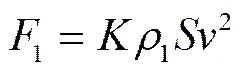
Where1is the force of the airflow, N;is the airflow velocity, m/s;1is the air density, kg/m3;is the area of plastic film blown by the air, m2;is the coefficient of resistance,=1.
From the formula above, the force of the airflow is related to the airflow velocity and the acting area of the airflow on the ARPF with all other parameters left unchanged. The force of the airflow increases with the increase in airflow velocity and acting area.
The adhesive force between the ARPF and the conveying belt is related to the humidity of the ARPF, the property of the soil attached to the ARPF and the clamping force acting on the ARPF as the ARPF is being carried. The quantity of ARPF collected cannot be determined due to the complicating influences of these factors above, so the adhesive force of the ARPF also cannot be calculated. Therefore, the experimental method was used to determine the dimensions of the nozzle and the airflow velocity. The ARPF could fall off when the airflow exit areaof the nozzle was 6.4×10⁻³m2and the airflow velocitywas5.03 m/s. The calculation of the total flow of the airflow exits was 575.89 m3/h.
In order to reliably remove film in complex field conditions, a fan of 4-68 No.3.8A model was selected. Its working speed is 1 450 r/min, its total pressure is 345 Pa and the air volume is 1 350 m3/h.
The air chamber should have a certain volume to ensure the uniformity and stability of the airflow exit. Its parameters (length×width×height) are 1 800 mm×300 mm×300 mm.
The airflow velocity was measured using the kasda-K0603 model (0-20 m/s) anemometermade by the Kasda Company. The wind speed of each outlet was tested for 3 times. Their average values were 9.026, 8.902, 8.930, 8.840 and 8.710 m/s.
3 Analysis of working process
3.1 Film lifting
In the process of lifting the film from the ground, the shovels penetrate into the earth to a certain depth and scoop up a certain thickness of soil layer. The ARPF on the surface of the soil layer comes up with the soil layer. Themaximum height of the soil ascending along the film shovels may be regarded as the height of the ARPF from the ground. Given the assumption that the soil is not deformed during the initial stages of being scooped up, the force acting on the soil layer is shown in Fig.6. As the soil layer ascends the shovel, the quantity of soil on the shovel surface increases. Thus, the frictionbetween the soil layer and the shovel increases, which causes an increase in the thrustthat is acting on the lower end of the soil layer (the part nearest to the ground)[32]. Due to the limited compressive strength of the soil layer, a crushing failure would occur at the lower end of the soil layer as the thrustincreases, and the soil layer would no longer be able to rise.
At the point of the damaged soil layer, the mechanical equilibrium equation in the direction of the shovel surface is as follows
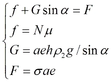
The mechanical equilibrium equation perpendicular to the shovel surface is as follows
(3)
The stress and strain equation of the soil is calculated by the following equation[32]
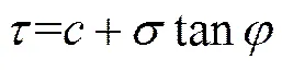
Whereis the weight of the soil layer, N;is the pressure of the shovel surface acting on the soil layer, N;is the thrustof the lower end of the soil pushed by the ground soil, N;is the friction between the shovel and the soil layer, N;is the internal friction angle of the soil layer, (°);is the width of the soil layer, m;is the thickness of the soil layer, m;is the rising height of the soil layer along the shovel, m;2is the soil density, kg/m3;is accelerationofgravity,m/s2;is the compressive stress acting on the soil layer, Pa;is the shear stress without normal load, Pa;is the maximum shear stress, Pa;is the installation angle of the shovel, (°).
The rising height of the soil layercan be obtained from the formula above.
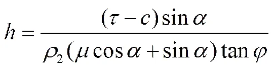
The above equation (5) indicates that the rising height (along the shovel surface) of the soil layerdepends on the penetration angle of the shovel. As the penetration angle is increased, the rising height of the soil layer is increased. However, the thrust strength of the soil layer is low. As the CCFR moves along, the extrusion acting on the soil by the shovel increases with the increase in the penetration angle, causing the soil on the ground to break. Therefore, when the penetration angle increases to a certain degree, the height of the soil layer stops increasing.
3.2 Clamping and conveying
After being scooped up from the ground and moved up along the surface of the shovel with the soil layer, the ARPF is scraped then onto the conveying belt by the scrapers, and is then clamped and conveyed to the film removal mechanism by the rotation of the scraper and the conveying belt.
Because the ARPF that is in a sheet on the ground has a certain strength, and the ARPF that is draped over theconveying belts is clamped onto the belts, the ARPF is subjected to the tensions from the soil and stalks on the ground at both sides of the conveying belt. These forces might make the ARPF slide off the conveying belt. Under such conditions, the ARPF would be subject to a transverse friction force from the scrapers and the conveying belts. Supposing the tension to be perpendicular to the surface of the conveying belt, and given that the quantity of ARPF is irrelevant since it weighs so little, the forces acting on the ARPF in the process of film clamping and conveying are shown in Fig.7.
If the value of2is greater than3, it needs to satisfy the following equation to prevent the ARPF from falling from the conveying belts
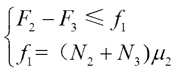
The force of the ARPF perpendicular to the conveying belt is as follows
(7)
Where2is the supporting force of the conveying belt acting on the ARPF, N;3is the clamping force of the scraper acting on the ARPF, N;1is the friction force of the conveyer belt and the scraper acting on the ARPF, N;2and3are the tensions from the ground soil and straw from both sides of the conveying belt acting on the ARPF, respectively, N;2is the friction coefficient between ARPF and the conveying belt or the scraper.
From Eq. (6) to (7):
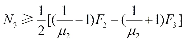
In order to prevent the ARPF from sliding down, it is assumed that the value of3is zero, and then the formula (8) can be simplified as
(9)
Given the complex conditions that occur in the actual fields, the value of2cannot be determined theoretically. The maximum tensile strength of the ARPF could be taken as the value of2. According to experiments, the ARPF would rupture at the clamping point when it was clamped by the scraper and the conveying belt. The experimental results indicated that the maximum tensile strength of the ARPF (0.008 mm in thickness) is 6.1 N, and in this case the value of2is 6.1 N.
The friction coefficient2of the ARPF between the scraper and the conveying belt is 0.4. The minimum pressure3of the scraper acting on the conveying belt is 4.58 N as found through calculation by Eq. (9). Therefore, in order to prevent the ARPF from sliding down, the minimum clamping force required for conveying the ARPF was 4.58 N.
The clamping force between the scraper and the conveying belt is not detected in actual operation. But the minimum clamping force is too small. Through adjusting the clearance between the scraper component and the conveying belt component on the condition of the haulage chain being tension, the minimum clamping force can be guaranteed.
In addition, the matching relationship between the advance speed of the machine and the speed of the conveying belt has an important effect on the ARPF recycling, because the ARPF is soft and its strength is low. If the speed of the conveying belt is less than the speed of the machine, the ARPF could not be scraped in time and would instead be mixed with the soil and stalks, blocking the shovels and impacting the scraping operation of the shovels. If the speed of the conveying belt is higher than the speed of the machine, less ARPF will be scooped up by the shovels. The ARPF would be easily broken up and less of it would be scraped onto the conveying belt. Therefore, the speed of the conveying belt and the advance speed of the machine should be equal to prevent the ARPF from being broken up and the shovels being blocked.
4 Field test
4.1 Conditions
The field test was carried out on the regimental farm of 143, Shihezi, on October 16th, 2014. For the test field, the cotton was harvested, and the cotton stalks and ARPF were left on the ground. The plant spacing of the cotton was 80 mm, the row spacing of the cotton was 660 mm, and the height of the cotton stalks was 700-850 mm. The ARPF attached to the ground was in a sheet. The ARPF thickness was 0.008 mm. The surface of the field was flat.
The prototype of the CCFR was mounted on the 4JM-1 cotton stalk chopping and film collecting machine. It was towed by a Foton Lovol M800-D model tractor. The field experiment is shown in Fig.8.
4.2 Targets and method
The mass of water and soil in the sampled ARPF was larger more than that of pure ARPF when the ARPF covered land surface for a long time. Therefore, there could be meaningless to test the impurity rate of the ARPF. This field experiment was to test the performance of removing and recycling the ARPF of this prototype.
The prototype moved along the rows of cotton plant at an operational speed of 5-5.5 km/h. The length of the test area was 60 m, and the test area was divided into fiveworking trips. In each trip, five detection points were randomly selected with the length of 2 m, and the average value of the five detection points was calculated as the test result of the trips. Then, a sample of the ARPF was taken and its size was the same as the test area. Its mass1was weighed after cleaning up. Finally the ARPF left on the ground was picked up and weighed its mass2after cleaning up.
The recycling rate of the ARPF was calculated by the following equation
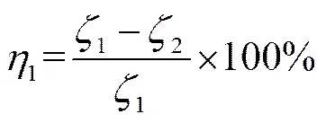
Where1is the recycling rate of the ARPF, %;1is the total mass of the ARPF in each test area, g;2is the mass of the ARPF left on the ground, g.
The film removal rate was determined by the quantity of ARPF in the film box and the quantity of ARPF wound onto the ARPF recycling device in a single working trip. When a field experiment was completed, the mass of the ARPF after being cleaned up for the film in the box was recorded as3, and the mass of the ARPF wound onto the collecting device was recorded as4. The removal rate was calculated with the following equation
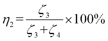
Where2is the removal rate of the ARPF, %;3is the mass of ARPF in recycling box, g;4is the mass of ARPF which wound onto the film collecting device, g.
4.3 Results
The recycling rate and the removal rate of each trip are shown in Table 2.
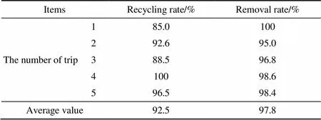
Table 2 Test result
The results of the field experiment indicated that the average recycling rate of the ARPF was 92.5% and the average removal rate of the ARPF reached 97.8%. When the depth at which the shovels entered the soil was 30-50 mm, the shovels worked efficiently without hilling the soil.
The stubble and the soil covered on the edge of the ARPF had a great compaction on the ARPF. When the shovels were not in a straight line along with the stubble or the edge of ARPF, this part of ARPF would be difficult to recycle. This could be the main reason why the ARPF was not fully recycled.
The soil and ARPF on the shovel were scrapped by the scrapers, which could prevent the ARPF from clogging in shovels to some extent. In the process of conveying the ARPF, more than half of stalk and soil mixed in the ARPF could fall from the CCFR device. Less than half of stalk and soil fell into the film box.
When the ARPF was transported to the driving belt wheel, a small amount of ARPF entered into the driving belt wheel groove, and then was clamped by the conveying belt. This part of ARPF was not removed by the pneumatic removal mechanism, which made the ARPF wind around the film collecting device.
5 Discussion
The ARPF in a sheet on the ground has certain strength after cotton being harvested. While the shovels entering the soil in a angle, the ARPF can be scooped up from ground, it is are helpful to recycle the ARPF. The penetrating angle of shovels andthe spacing between two shovels are the main factors affecting the ability of picking up the ARPF. When the penetrating angle is small, the ARPF can move up along the surface of the shovelsmoothly. Then the ARPF is easily scraped to the conveying belts from the surface of the shovels. When the spacing is small, the number of shovel will increase which is helpful to pick up the ARPF. But the stalk and soil would block the shovels and the recycling rate of the ARPF might be affected.
When the scrapers are pressed on the conveying belts, elastic deformation occurs in the contact position between scraper and the conveying belt. Suppose the space between haulage chains and conveying belts is small and haulage chains is tension, elastic deformation of scrapers would exist, so scrapers will act a continuous pressure on the conveying belts. In addition, in order to prevent the clamping force from being weakened which is caused by the permanent deformation of scraper, the scraper could be made of the rubber material.
When scrapers leave conveying belts at the upside of the film box, most of the ARPF can fall into the film box by gravity. The other ARPF adheres to the conveying belt by the adhesion force which is relatively very small. The ARPF adhered can fall into the film box under the action of pneumatic film removal mechanism. The main factors affecting the removal rate of the ARPF include air velocity, area of airflow acting on the ARPF and position of air outlet of nozzle. Except for the size of nozzle and the position of air outlet of nozzle, the adhesion force and the area of airflow acting on the ARPF could not be determined. Therefore, increasing air velocity of the nozzle is a feasible method to guarantee the removal rate of the ARPF.
There are stubble and a small amount of stalk left on the ground after stalk crushed and cleared by the stalk smashing and conveying device. When the machine works, some soil and stalk mixed in the ARPF might be clamped and conveyed between the scraper and the conveying belt. As the conveying belt being narrow, the soil and stalk, clamped and conveyed is limited. The stalk and soil, mixed in ARPF between two conveying belts, is difficult to separate from ARPF now. The stalk and soil mixed in the ARPF could be cleared by fixing film cutting disc between shovels. It will be next work for ARPF recycling research.
6 Conclusions
1) When the width of the shovel was 80 mm, the shovel angle was 25°, the spacing of two adjacent shovels (from each other) was 350 mm, and the depth at which the shovels entered the soil was 30-50 mm, the shovel could pass through the ground without hilling and the agricultural residual plastic film (ARPF) left the ground with the soil layer as it was scooped up by the shovel.
2) The shield and the blade could effectively prevent the soil and weeds from sticking to and winding around the driven belt pulley.
3) Through adjusting the clearance between the scraper component and the conveying belt component on the condition of the haulage chain being tension, the ARPF could be clamped and conveyed in a stable and reliable way by the clamping-conveying mechanism. In order to convey the agricultural residual plastic film (ARPF), it was found that the minimum clamping force was 4.58 N.
4) When the operating speed of the prototype was 5-5.5 km/h, the results of the field experiment indicated that the average recycling rate of the ARPF was 92.5% and the average removal rate of the ARPF reached 97.8%.
5) When the film was removed, the clamping force of the scraper disappeared and the pneumatic force of the film removing device could overcome the adsorption between the ARPF and the film collecting parts. In this way, the residual plastic film could be taken off easily and prevented from winding around the working parts.
[1] ZhiYan Co. Ltd. Analysis of the operational status and investment prospect of agricultural film industry in China in 2013-2018[Z]. ZhiYan Co. Ltd., 2013.
[2] Bi Jiye, Wang Xiufen, Zhu Daolin. Effect of plastic-film mulch on crop yield[J]. Transactions of the Chinese Society of Agricultural Engineering (Transactions of the CSAE), 2008, 24(11): 172-175.
[3] Xie Honge, Li Yongshan, Yang Shuqiao, et al. Influence of residual plastic film on soil structure, crop growth and development in fields[J]. Journal of Agro-Environment Science, 2007, 26(Supp.): 153-156.
[4] Wu Jianshe, Chen Xuegeng. Present situation, problems and countermeasures of cotton production mechanization development in Xinjiang Production and Construction Corps[J]. Transactions of the Chinese Society of Agricultural Engineering (Transactions of the CSAE), 2015, 31(18): 5-10.
[5] Liu Jianguo, Li Yanbin, Zhang Wei, et al. The distributing of the residue film and influce on cotton growth under continuous cropping in oasis of Xinjiang[J]. Journal of Agro-Environment Science, 2010, 29(2): 246-250.
[6] Yan Changrong, He Wenqing, Liu Enke, et al. Concept and estimation of crop safety period of plastic film mulching[J]. Transactions of the Chinese Society of Agricultural Engineering (Transactions of the CSAE), 2015, 31(9): 1-4.
[7] He Wenqing, Yan Changrong, Zhao Caixia, et al. Study on the pollution by plastic mulch film and its countermeasures in China[J]. Journal of Agro-Environment Science, 2009, 28(3): 533-538.
[8] Yan Changrong, Mei Xurong, He Wenqing, et al. Status and control of agricultural plastic film residue pollution[J]. Transactions of the Chinese Society of Agricultural Engineering (Transactions of the CSAE), 2006, 22(11): 269-272.
[9] Dong Hegan, Liu Tong, Li Yongguan, et al. Effects of plastic film residue on cotton yield and soil physical and chemical properties in Xinjiang[J]. Transactions of the Chinese Society of Agricultural Engineering (Transactions of the CSAE), 2013, 29(8): 91-99.
[10] Li Bin, Wang Jikui, Jiang Bei. The plastic film pollution and treatment technology in Xinjiang cotton area[J]. Journal of Agricultural Mechanization Research, 2012(5): 228-232.
[11] Li Yuanqiao, He Wenqing, Yan Changrong, et al. Effect of residual film on soil infiltration under drip irrigation[J]. Transactions of the Chinese Society of Agricultural Engineering (Transactions of the CSAE), 2015, 31(6): 145-149.
[12] Du Xiaoming, Xu Gang, Xu Duanping, et al. Mulch film residue contamination in typical areas of north China and countermeasures[J]. Transactions of the Chinese Society of Agricultural Engineering (Transactions of the CSAE), 2005, 21(Supp.1): 225-227.
[13] Yan Changrong, Liu Enke, Shu Fan, et al. Review of agricultural plastic mulching and its residual pollution and prevention measures in China[J]. Journal of Agricultural Resources and Environment, 2014, 31(2): 95-102.
[14] Lü Zhaoqin, Zhang Lei, Zhang Guangling, et al. Design and test of chain guide rail-type plastic film collector[J]. Transactions of the Chinese Society of Agricultural Engineering (Transactions of the CSAE), 2015, 31(18): 48-54.
[15] Hou Shulin, Hu Sanyuan, Kong Jianming, et al. Present situation of research on plastic film residue collector in China[J]. Transactions of the Chinese Society of Agricultural Engineering (Transactions of the CSAE), 2002,18(3): 186-190.
[16] Cao Silin, Wang Xujian, Shen Congju, et al. Patent analysis on mechanization technology of retrieving the used plastic film[J]. Chinese Agricultural Mechanization, 2009(4): 48-50.
[17] Chen Fa, Shi Jianxin, Wang Xuenong, et al. Study on collecting principle of arc-type tooth roller for collecting plastic residue[J]. Transactions of the Chinese Society of Agricultural Machinery, 2006, 37(6): 36-41.
[18] Wang Wenming, Wang Chunguang. Parameter analysis and simulation of spring-finger cylinder pickup collector[J]. Transactions of the Chinese Society for Agricultural Machinery, 2012, 43(10): 82-89.
[19] Wang Jikui. Farmland Residual Film Recycling Technology[M]. Shanxi Northwest A&F University press, 2012.
[20] Duan Wenxian, Wang Jikui, Li Yang, et al. Design of clamping finger-chain type device for recycling agricultural plastic film[J]. Transactions of the Chinese Society of Agricultural Engineering (Transactions of the CSAE), 2016, 32(19): 35-42.
[21] Mu Daohuan, Yang Wanzhang. Design and experimental research on spring-tooth picking mechanism of residual film collector[J]. Journal of Agricultural Mechanization Research, 2015(6): 89-92.
[22] Xie Jianhua, Hou Shulin, Zhang Xuejun, et al. Optimization design of unloading residual plastic film mechanism based on the predetermined trajectory[J]. Journal of Agricultural Mechanization Research, 2015(6): 89-92.
[23] Ma Shaohui, Zhang Xuejun. The rudimental plastic harvesting machinery’s present condition and developing trend[J]. Journal of Agricultural Mechanization Research, 2006(5): 37-38.
[24] Ma Hui, Mei Xurong, Yan Changrong, et al. The residue of mulching plastic film of cotton field in north China[J]. Journal of Agro-Environment Science, 2008, 29(2): 246-250.
[25] Wang Jikui, Fu Wei, Wang Weibing, et al. Design of SMS-1500 type straw chopping and plastic film residue collecting machine[J]. Transactions of the Chinese Society of Agricultural Engineering (Transactions of the CSAE), 2011, 27(2): 570-573.
[26] Li Bin. The Working Mechanism Research on Rear Chain Harrow Residual Film Recycling Machine[D]. Shihezi: Shihezi University, 2013.
[27] Wang Xuenong, Shi Jianxin, Guo Junxian, et a1. Experimental study and design on film raking mechanism of hanging film raker with cotton stalk crushing and returning to field[J]. Transactions of the Chinese Society of Agricultural Engineering (Transactions of the CSAE), 2008, 24(1): 135-140.
[28] Yan Panpan, Cao Silin, Luoxin, et al. Research on the spring-tooth-chain-rake incomplete plastic film recycling machine[J]. Journal of Agricultural Mechanization Research, 2016(6): 137-142.
[29] Wang Haixin, Zhang Xuejun, Zhang Chaoshu, et al. Based on the stud type residual film recycling machine in the film the design of the spade[J]. Journal of Agricultural Mechanization Research, 2016(6): 137-142.
[30] Zhang Xuejun. Study on Separation and Transport Device for Remnant Plastic Film[D]. Changchun: Jilin University, 2007.
[31] Hu Kai, Wang Jikui, Li Bin, et al. Development and experiment of combined operation machine for cotton straw chopping and plastic film collecting[J]. Transactions of the Chinese Society of Agricultural Engineering (Transactions of the CSAE), 2013, 29(19): 24-32.
[32] China Agricultural University. Agricultural Mechanics[M]. Beijing: China Agriculture Press, 1991.
夹持输送式残膜回收装置的设计与试验
李天文,段文献,王吉奎※,李 阳,毕新胜,龚贺贺,丁双双
(石河子大学机械电气工程学院,石河子 832003)
针对现有残膜回收机存在残膜回收率低、残膜缠绕和脱膜困难的问题,依据残膜特性,设计了一种气力脱膜的夹持输送式残膜回收装置,该置主要由起膜机构、输送机构和气力脱膜机构组成,通过介绍夹持输送式残膜回收装置的工作过程,分析讨论确定起膜铲、夹持输送结构和脱膜机构的结构和工作参数,选取刮板和输送带的材料以及刮板组件和输送带的位置关系;分析起膜铲铲起残膜过程和残膜沿起膜铲上升的高度,分析夹持输送残膜时残膜受力,确定输送残膜所需夹持力的最小值为4.58 N。田间试验表明:起膜铲可以将地表残膜铲起,铲起的残膜在刮板的作用下可以顺利喂入夹持输送机构,残膜在输送过程中可以被稳定夹持,气力脱膜机构可以将夹持输送的残膜顺利脱下,防止残膜粘附缠绕,当机具作业速度为5~5.5 km/h时,残膜平均回收率达到92.5%,平均脱膜率达到97.8%。该研究可为研制残膜回收机提供参考。
农业机械;设计;回收;残膜;装置;夹持输送;气力脱膜
10.11975/j.issn.1002-6819.2016.24.003
S223.5
A
1002-6819(2016)-24-0018-08
date:2015-10-18 Revised date:2016-11-02
National Natural Science Foundation of China (51465050)
Wang Jikui, man, professor, engaged in agricultural mechanization engineering. Shihezi College of Mechanical and Electrical Engineering, Shihezi University, 832003. Email:shzwjk@126.com
Biography:Li Tianwen, man, candidate, engaged in innovation and performance design of agricultural machinery. Shihezi College of Mechanical and Electrical Engineering, Shihezi University, 832003. Email:zfengltw0322@163.com.
猜你喜欢
机电工程技术(2021年12期)2021-08-21
今日农业(2020年16期)2020-12-14
基层中医药(2020年9期)2020-11-27
环球时报(2020-03-30)2020-03-30
农家书屋(2019年4期)2019-03-16
今日农业(2019年4期)2019-01-04
今日农业(2019年5期)2019-01-03
农机化研究(2017年3期)2017-12-16
艺术评鉴(2017年16期)2017-09-20
中国农业文摘-农业工程(2016年5期)2016-04-12