
Operation of the main steam inlet and outlet interface pipe of a nuclear power station①
2017-12-19 00:39HuangGuiping黄桂平XuanYabingZhangLinweiLiangXuewei
High Technology Letters 2017年4期
关键词:桂平
Huang Guiping (黄桂平), Xuan Yabing, Zhang Linwei, Liang Xuewei
(*School of Resources and Environment, North China University of Water Resources and Electrical Power, Zhengzhou 450000, P.R.China) (**Zhengzhou Chenway Technology Co., Ltd, Zhengzhou 450000, P.R.China) (***Citic Heavy Industry Machinery Co., Ltd, Luoyang 471003, P.R.China)
Operation of the main steam inlet and outlet interface pipe of a nuclear power station①
Huang Guiping (黄桂平)②, Xuan Yabing*, Zhang Linwei***, Liang Xuewei**
(*School of Resources and Environment, North China University of Water Resources and Electrical Power, Zhengzhou 450000, P.R.China) (**Zhengzhou Chenway Technology Co., Ltd, Zhengzhou 450000, P.R.China) (***Citic Heavy Industry Machinery Co., Ltd, Luoyang 471003, P.R.China)
A method is proposed to measure the process margin of the main steam inlet and outlet pipe of a nuclear power plant by using an industrial photogrammetry system. This method includes steps of preparation, image acquisition, image processing, and result analysis, as well as the final processing margin analysis, and so on. In particular, it suggests a specific method for target-point layout and design of shooting network for the main steam inlet and outlet pipe measurement, and then uses a method of sub-section photography and collation to measure the inner and outer surfaces of the nuclear power interface pipe.The machining tolerance analysis shows that the method can effectively test whether the machining tolerance data of the interface pipe’s top surface, outer surface and the inner surface reach a critical value, which provides a reliable reference for the next step in this process, and it is a type of machining tolerance detection method worthy of popularisation.
nuclear power interface pipe, machining tolerance, industrial photogrammetry system
0 Introduction
A nuclear power plant’s main steam inlet and outlet interface pipe (hereinafter referred to as “nuclear power interface pipe”) is assumed to have a role of connecting multiple pipes in the cooling water circuit, so its geometry is more complex. To guarantee accuracy, a three-dimensional measurement of the machining tolerance is needed, as the basis for subsequent alignment and finishing machining[1]. At present, the measuring methods of the casting blank are mainly as follows: one is a three-coordinate measuring method, and its main drawback is the use of environmentally demanding production sites: it is also hard to apply to large castings. Another is a three-dimensional scribing instrument measuring method, its main drawback is that it needs a special measuring platform, and a contact method and can only be applied to small-and-medium-sized casting measurement. Others include a photoelectric theodolite measurement method, joint arm or laser tracking measurement method, whose main shortcoming is high equipment cost, using complex and low efficiency machines for large castings and forgings[2-6].
Industrial photogrammetry uses image acquisition, processing, matching and calculation processes to measure the size and shape of the target. Then the shape and surface of the measured points are fitted and compared with the design model. Its features include: non-contact measurement, excellent dynamic performance, fast detection speed, little environmental impact, and it is especially suitable for the rapid detection of shape[7,8]. This paper introduces a detection method used to find the distribution of residual blank measurements and the related analysis.
1 Detection scheme design
This detection scheme uses an MPS/S36 industrial photogrammetry system, it is a set of optical three coordinate measuring system, which is made by Zhengzhou Chenway Technologies Inc. The system is mainly composed of high-resolution photogrammetry camera, auto-bar, length calibration scale-bar, reflective photographytarget-point, system software, and so on (Fig.1)[9].The system uses a high-resolution photographic measurement camera to capture the nuclear power interface pipe as two pieces or pieces of a digital image in different positions and orientations: through image pre-treatment, symbol recognition, image matching, spatial triangle intersection, and bundle adjustment, produces a 3-dimensional (3-D) coordinates of the measured point, and then obtains the 3-D sizes and shape of the nuclear power interface pipe.
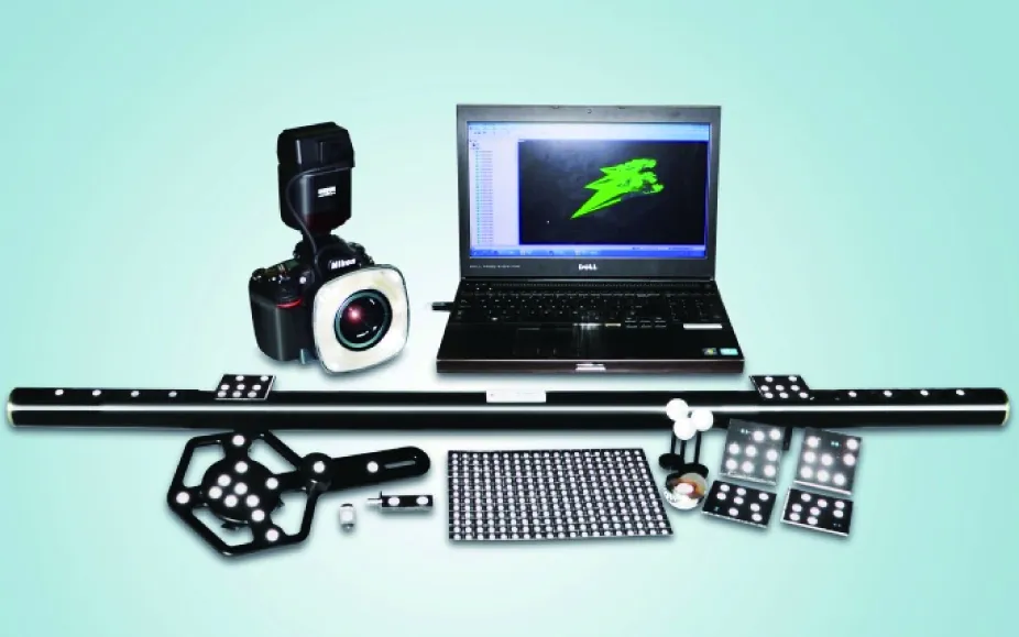
Fig.1 MPS/S 36 series industrial photogrammetry system
The specific detection plan includes the following parts: (1) site preparation; (2) image acquisition; (3) software processing; (4) processing of the results.
1.1 Site preparation
The main work involved in site preparation is the layout of the target-point and the placing of the length calibration scale-bar.In this measurement scheme, target-points mainly use circular reflective photography targets and a code target, and the length calibration scale-bar mainly uses the system’s own photogrammetric scale-bar, which is pre-calibrated. The target point layout scheme is as follows:
On both inside and outside surface of the nuclear power interface pipe, at intervals of 30°, bar-type reflective photographic targets are pasted and specific distribution is shown in Fig.2. The reflective targets are taken as the targets point on the surface of the nuclear power interface pipe’s inside and outside surface.In addition, the nuclear power interface pipe surface is pasted with 80 coded symbols, which play a role of image cohesion and matching in the measurement and calculation. To improve the accuracy of the measurement, taking into account the larger range of measurement and the nuclear power interface pipe needing to be turned over during the shooting process, the measurement uses four length calibration scale-bars. Using multiple length calibration scale-bars can not only constrain the whole nuclear power interface pipesize measurement, but also have the effect of cross-checking data, thus reducing errors.
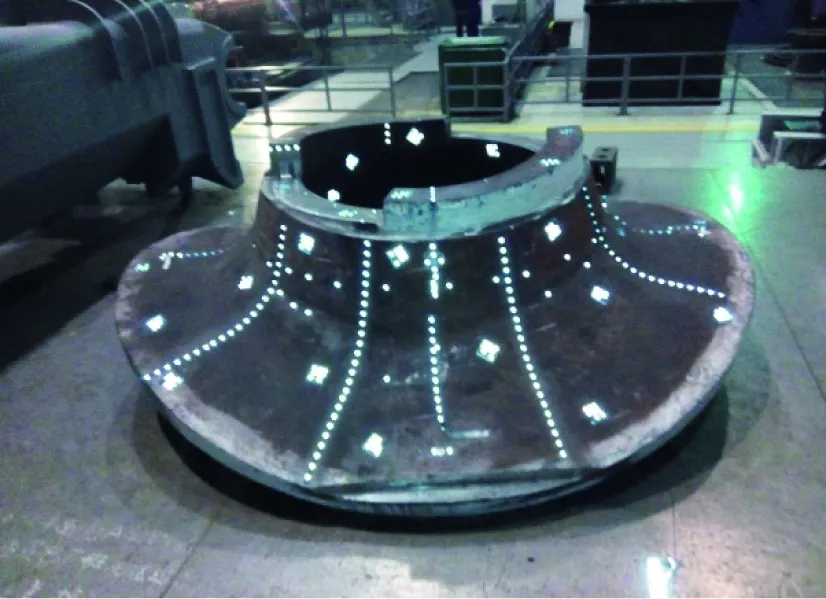
(a) External surface
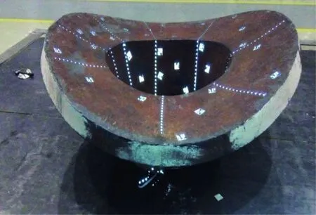
(b) The inner surface Fig.2 Target point layout diagram
1.2 Measuring net shape design and image acquisition
During image acquisition, the most noteworthy fact is the optimisation of the shape of the shooting network. Since both the inner and outer sides of the nuclear power interface need to be measured, along with their height and tilt angle, considering issues such as the view angle of the camera lens, photographic distance, measurement accuracy, survey site, and so on, the measurement on the whole surface of nuclear power interface pipe is divided into two steps: the interface pipe is put up and pictures of the external surface(as shown in Fig.2(a)) are taken and then the nuclear power interface tube is turned over to capture the inner surface (as shown in Fig.2(b)). When shooting according to the curvature of the nuclear power interface pipe, camera positions are changed, so that each photo includes the nuclear power interface tube as much as possible. The distance between the camera and the measured work-piece is about 3m. The specific distribution of the camera stations is shown in Fig.3.
1.3 Image processing and analysis
Photogrammetry uses the method of segment photography, as a global solution which uses code-targets as the common connection points between images. The connection points are the inside code-targets of the pipe orifice. The analysis is performed by MPS/S 36 system software. The 3-D coordinates of the measured points are obtained by the software through image pre-processing, mark recognition, image matching, spatial triangle intersection, and beam adjustment.Then according to the 3-D coordinates of the points, the geometric size measurement, deformation measurement, and reverse engineering analysis are carried out.
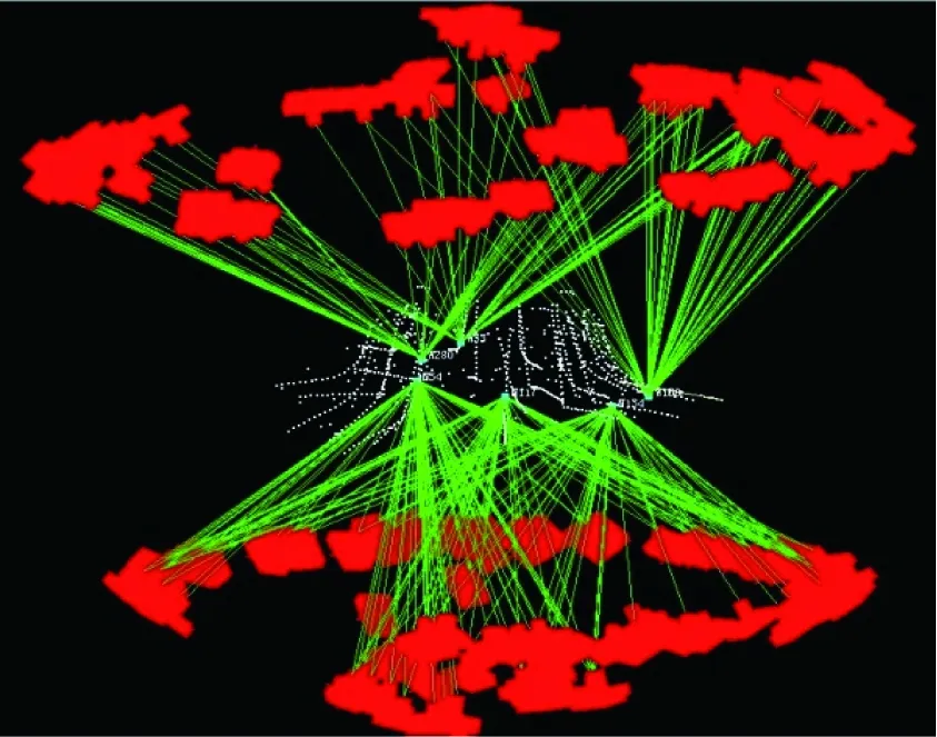
Fig.3 Distribution of camera stations
2 Machining tolerance calculation and analysis
The above test method is used to measure the nuclear power interface pipe, and the 3-D coordinates of the surface target point of the work-piece can be obtained. The next step is to calculate and analyse the machining tolerance.
2.1 Calculation principle
The tolerance is calculated by the CAD surface conversion method, which is a direct conversion with the measuring point and the design of the CAD surface (curved surface corresponding to the actual interface pipe size)[10,11]. The transformation principle is the initial value of coordinate conversion can be calculated by common point conversion methods. The measuring points are projected onto the theoretical surface, then take the projection point as the design coordinates of the common point to reopen the process of coordinate conversion; the new transformation parameters are obtained. Finally, the above steps are repeated and iterative computations are terminated when the point precision relative to the CAD surface of the measuring point is maximised[12].
Under the same coordinate system, data analysis of the entire nuclear power interface pipe is divided into three parts: the top surface, the inner surface, and the outer surface (as shown in Fig.4). Through the translation and rotation of the three axes, the position deviation and model design optimisation results are obtained and the deviations of each surface is stroven to balance to ensure no negative values occurr, thus providing a reliable reference for the next step of the machining process.
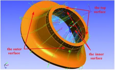
Fig.4 Data analysis diagram
2.2 The analysis of machining tolerance
For the measurement of nuclear power interface pipe, the working process tolerance of each process including the rough parts, their rough machining, and heat treatment to finish should be all controllable. In this phase, two measurements are recorded until the final product processing accuracy meets design requirements. After each measurement, using the 3-D point cloud measurement data and product design data model fitting comparison, the work-piece measurement data and design model parts deviations are checked, finally the optimal results can be obtained through translation and rotation of the coordinate axes. Table 1 is a few different types of nuclear power interface pipe machining allowance analysis statistics:
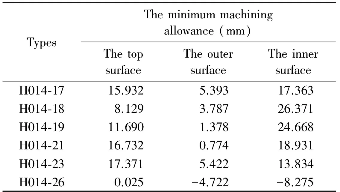
Table 1 Machining allowance results TAB
Table 1 shows that, for H014-26, the minimum of machining allowance is 0.025mm, -4.722mm and -8.275mm, respectively, corresponding to the top surface, outer surface and inner surface of the nuclear power interface pipe, and its machining allowance is insufficient.When adjusting the nozzle top surface data beyond the critical value of machining allowance, the inner surface and outer surface do not have enough processing volume. The top surface, outer surface and inner surface of the H014-17, H014-18, H014-19, H014-21, H014-23 workpiece have enough machining allowance.
Fig.5 shows the schematic diagram of the blank measurement and comparison of product design data model. The length of the arrow indicates the deviation of the 3-D point with respect to the design model, that is the next step of rough machining, which provides the basis for rough machining to tolerance. In Fig.6, the machining tolerance of the rough process after heat treatment is given, which provides a basis for the next finish-machining step. Through comparing the two figures it can be seen that the machining tolerance of the blank is larger than that after rough machining. It proves that this method can effectively test whether the data from the nozzle top surface, outer surface, and the inner surface reach the critical tolerances.
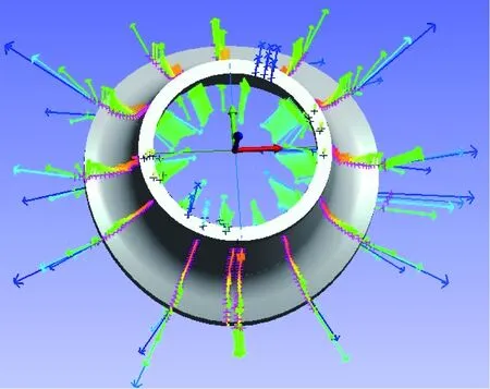
Fig.5 Distribution of blank machining tolerance

Fig.6 Distribution of machining tolerance after rough machining
3 Conclusion
Industrial photogrammetry has begun to be more widely used in the analysis of the working tolerances of castings and forgings, so far, Citic Heavy Industries have used this method to detect a number of types of artefacts. Their different diameters well illustrates the use of industrial photogrammetry in nuclear power interface pipe analysis.
Practice has proved that using an industrial photogrammetry system for the on-line measurement of a nuclear power interface pipe achieves full monitoring of its processing capacity, and can analyse the deviation from design tolerances and deformation at each working stage of its processing. The test results can meet the requirements of machining accuracy, the measurement process is simple, and the environmentally-imposed requirements are low.
[ 1] Tian C H. The NC machining of interface pipe of a nuclear evaporator. Metal Working Cutting, 2008, (21):60-63
[ 2] Zhou L M. Digital Measuring Analysis and Process Compensation for Machining Allowance of Casting Blank: [Ph.D dissertation ]. Chengdu: School of Mechanical Engineering, Southwest Jiaotong University, 2013. 21-35 (In Chinese)
[ 3] Zhang Y, Liu M, Zhang D H, et al. An adaptive approach for machining allowance balancing for blade based on online measurement. Computer Technology and Development, 2014, 24(11):227-233 (In Chinese)
[ 4] Gai C, Chen W, Lv Y M, et al. Research on technology of designing stock of blade forgings. Hot Working Technology (Casting & Forging), 2006, 35(04):51-53
[ 5] Liu J Y, Jennifer T. Application of three dimension inspection in development of metal mould casting Product. Foundry Technology, 2015, 36(03):820-822+825 (In Chinese)
[ 6] Zhang S C , Yang Y Q, Zhang S H, et al. Application of three dimensional laser scanning technology in the measurement of the size of castings. Automobile Technology & Material, 2012, 12:61-64 (In Chinese)
[ 7] Huang G P. Digital Close Range Industrial Photogrammetry Theory, Method and Application. Beijing: Science Press, 2016. 8-12
[ 8] Huang G P. Study on the Key Technologies of Digital Close range Industrial Photogrammetry and Applications :[Ph. D dissertation]. Tianjin: School of Precision Instrument and Opto-Electronics Engineering, Tianjin University, 2005. 9-16 (In Chinese)
[ 9] Huang G P. MPS/S series single camera industrial photogrammetry system. http: //www.chenway.cn/product/prod1/7.html:Chenwei,2016
[10] Li Z C, Li G Y, Jin C. On the date processing methods of surface antenna’s calibration. Journal of Astronautic Metrology and Measurement, 2003, 23(2):12-19 (In Chinese)
[11] Huang G P, Wang W F, Xuan Y B, et al. Research progress on calibrating methods of industrial photogrammetry system. China Measurement & Test, 2015, 7:10-15 (In Chinese)
[12] Chen X, Feng Q Q, Li Z C. A new method for testing the precision of photogrammetry. Engineering of Surveying & Mapping, 2010, 19(2):53-55+58 (In Chinese)
10.3772/j.issn.1006-6748.2017.04.013
①Supported by the National Natural Science Foundation of China (No. 41301598), the Open Fund Program of Henan Engineering Laboratory of Pollution Control and Coal Chemical Resource Comprehensive Utilization (No. 502002-B07, 502002-A-04).
②To whom correspondence should be addressed. E-mail: huangguiping123@163.com
on Sep. 1, 2016*
his Ph.D degree in the State Key Laboratory of Precision Measurement Technology and Instruments of Tianjin University in 2005. He also received his B.S. and M.S. degrees from Institute of Surveying and Mapping, the PLA Information Engineering University in 1996 and 1999 respectively. His research interests include engineering precision measurement, industrial photogrammetry.
猜你喜欢
今日农业(2020年23期)2020-12-15
文史春秋(2019年10期)2019-12-21
科教新报(2019年19期)2019-09-10
林业与生态(2019年2期)2019-04-12
火花(2018年10期)2018-11-01
中国经济周刊(2016年26期)2016-07-23
名作欣赏(2011年16期)2011-08-15
 High Technology Letters2017年4期
- High Technology Letters的其它文章
- Temperature field analysis of two rotating and squeezing steel-rubber rollers①
- Research on a toolpath generation method of NC milling based on space-filling curve①
- Studies on China graphene research based on the analysis of National Science and Technology Reports①
- First order sensitivity analysis of magnetorheological fluid damper based on the output damping force①
- Research on characteristics of integrated type hydraulic transformer’s control angle①
- Novel differential evolution algorithm with spatial evolution rules①