水稻精量穴直播机电驱式侧深穴施肥系统设计与试验
2018-05-13 17:46WangJinwuLiShuweiZhangZhaoLiQichao
农业工程学报 2018年8期
Wang Jinwu, Li Shuwei, Zhang Zhao, Li Qichao
(Engineering College, Northeast Agricultural University, Harbin 150030, China)
0 Introduction
Rice direct-seeding is a kind of labor-saving,time-saving, energy-saving and cost-saving planting way[1-4].Currently, surface fertilization and full-layer fertilization are mostly used in fertilization with rice direct-seeding in China.As a result of limited fertilizer absorption of rice, excessive use of fertilizer will cause waste of resources and environment pollution in the long term[5-8]. Domestic scholars began to study rice direct-seeding and fertilizing machine. Xia Junfang et al[9]proposed a kind of 2BFS-8 rice planting and fertilizing machine, and rice seeds could be drilled on the ridge and fertilizer were manured onto the fertilizer furrow. Luo Xiwen et al. put forward precision rice hill-drop drilling principle with opening furrows, forming ridges, and applying fertilizer synchronously[10-11]. A precision rice hill-drop drilling machine for dry land with opening furrows, forming ridges and applying fertilizer synchronously was developed, which was matched with the above principle[12]. According to the rice production situation in Heilongjiang Province, Dong Kehong et al[13]developed a new fertilizing and rice direct-seeding machine for the cold area. Machines mentioned above can complete side deep application of fertilizer in the process of rice direct-seeding, possibly resulting in excessive use of fertilizer and low utilization rate of fertilizer.
With the side deep hill-drop fertilizing technology for paddy fields, the fertilizer can be centrally manured at certain depth and side of rice seedling during hill-drop fertilization, and fertilizer can be covered by mud around rice seeds[14-17], which can reduce the volatilization of fertilizer, improve the utilization rate of fertilizer, reduce the cost of unit yield, promote the growth of rice, enhance yield of rice and protect ecological environment. At present, the side deep hill-drop fertilization device that matched precision rice direct-seeding machine has not been reported,so that it is necessary to carry out the related research.
The electrical drive side deep hill-drop fertilization system for precision rice hill-direct-seeding machine was developed and reorted in the paper, which can ditch furrows,realize side deep hill-drop fertilization, cover soil, and form ridges in the process of precision hill-direct-seeding. In the field, certain amount fertilizers can be manured at the fixed location of rice root system through hill-drop way, and fertilizer furrow can be covered with mud, which can reduce waste of fertilizer, save cost and enhance efficiency.Combining with precision rice hill-direct-seeding technique and side deep hill-drop fertilization technique, the research on precision rice hill-direct-seeding machine and fertilization key components is of important research value and has production and application prospect.
1 Overall structur e and working principle of
electrical drive side deep hill-drop fertilization and precision rice hill-direct-seeding machine
1.1 Overall structure
The developed electrical drive side deep hill-drop fertilization system and the precision rice seed-metering device are combined to form the electrical drive side deep hill-drop fertilization and precision rice hill-direct-seeding machine. The integration machine is hung with transplanter chassis by three-point suspension.Key parts of the machine are placed from front to back,including horizontal profiling mechanism, height profiling mechanism, sliding and cutting type fertilizer furrow opener (the following is abbreviated as fertilizer furrow opener), electrical outer slot wheel fertilizer applicator (the following is abbreviated as fertilizer applicator), precision rice hill-direct seed-metering device(the following is abbreviated as seed-metering device),and the structure of machine is shown in Figure 1.Auxiliary parts include frame, suspension bracket,boat-type board, water furrow opener, fertilizer case, seed case, seeding shaft, sliding board, and gearbox. The height profiling mechanism is located in front of the fertilizer furrow opener. The horizontal profiling mechanism is located upon the fertilizer furrow opener,and fertilizer applicators and seed-metering devices are installed on the frame. Water furrow openers are fixed to boat-type board that fixedly connected with rack.
The machine can realize the operations of ditching furrows, side deep hill-drop fertilization, covering mud,forming ridges and precision rice hill-direct-seeding synchronously. Table 1 shows technical parameters of the machine.
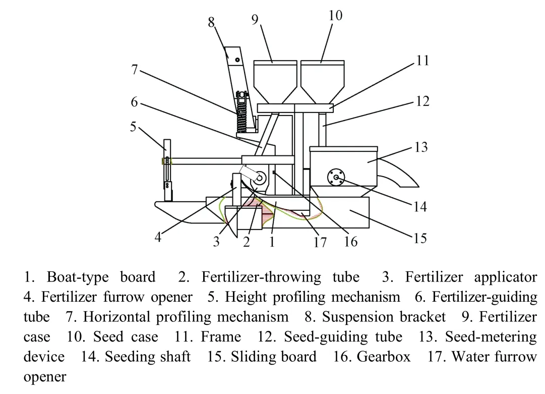
Fig.1 Overall Structure of electrical drive side deep hill-dropfertilization and precision rice hill-direct-seeding machine

Table 1 Main technical parameters of integration machine
1.2 Design of transmission system
Power transmission system is shown in Figure 2. The power is from the motor of 14.4 kW Kubota transplanter chassis. The rear power output universal drive shaft and the dynamic input end of the integration machine are connected by coupling. When operating speed is 2.48 km/h, power output shaft rotation speed is 596 r/min, and via bevel gearbox way, the one-stage power deceleration is completed,the transmission ratio of which is 13:1, then power is transmitted to sprocket 5 directly connected to the gearbox.The power of output shaft is transmitted to sprocket 8 (fixed on the seeding shaft) by chain driving way, thus the two-stage power deceleration is completed, the transmission ratio of which is 19:12. Then the power is transmitted to seeding shaft, which can drive rotation of seed-metering device to complete seeding operation. The power of fertilizer applicator is provided by DC storage battery of 12 V at transplanter chassis. When the circuit is switched on after fertilizer applicator, governor and motor were connected through wire so that the fertilizer applicator can complete the fertilizing operation.
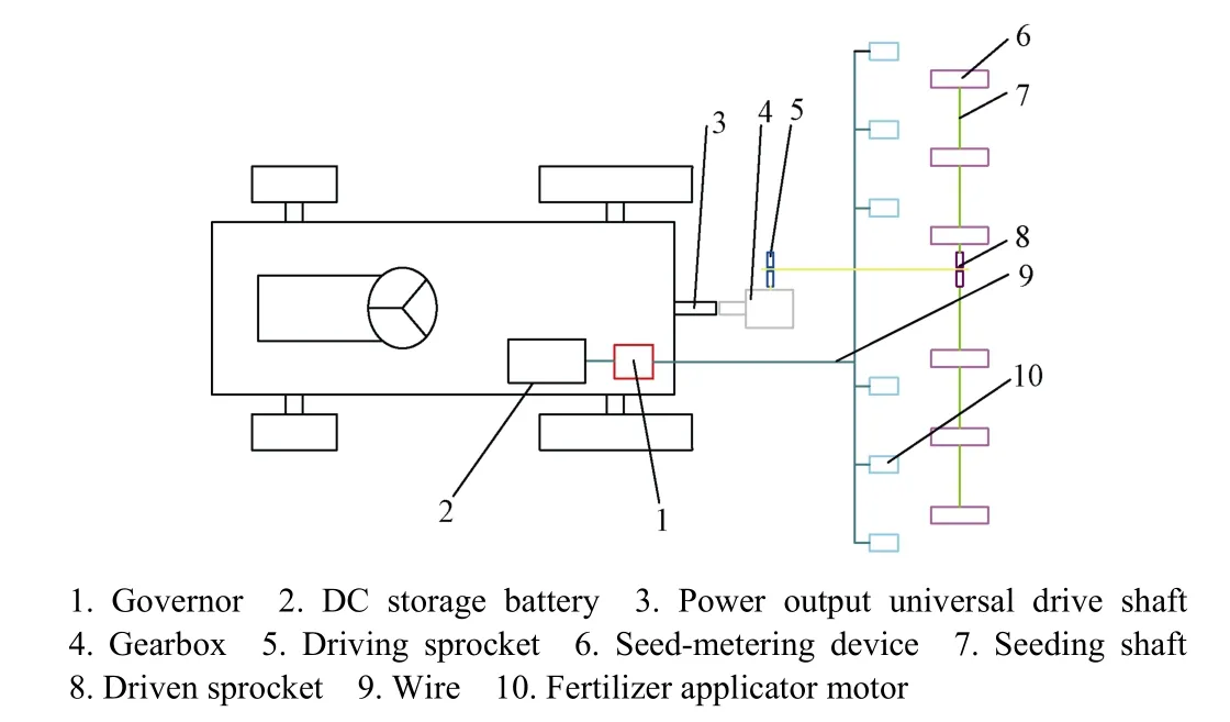
Fig.2 Schematic diagram of power transmission system
1.3 Worki ng principle
The working principle of the integration machine for electrical drive side deep fertilization and precision rice hill-direct-seeding is shown in Figure 3. First by fertilizing furrow openers, the fertilizer furrows are ditched on the soft and flat surface, the cross section of fertilizer ditch is a rectangle, furrow width is 50 mm and furrow depth is adjustable. Boat-type board covers mud after that the fertilizer is hill-drop manured onto the fertilizer furrow with certain hill spacing; Water furrow openers under the boat-type board, which synchronously ditch parallel water furrows. The section of water furrow is a trapezoid, the upper and under widths of which are 100 and 80 mm, and depth is 40 mm; Then, adjacent water furrows form ridge,which is higher than water furrow; Finally, seeds are sowed on the ridge with same hill spacing in a hill-direct way. The fertilizer row is located on one side of the bud row, fertilizer furrow is 30 mm from seed row, the depth of which is 50 mm from the ridge.
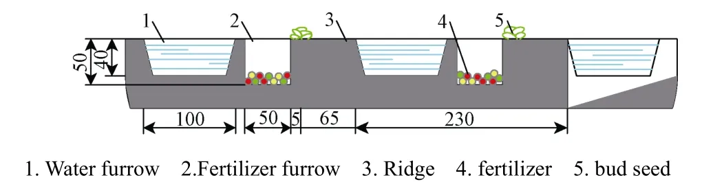
Fig.3 Working principle of precision rice hill-direct -seeding and side deep hill-drop fertilization
2 Design of critical parts of ele ctrical drive side deep hill-drop fertili zation and precision ri ce hill-direct-seeding machine
2.1 Design of omni-directional profiling system
1) Horizontal profiling mechanism
As shown in Figure 4, the horizontal profiling mechanism mainly consists of spring, guiding rod and connecting rod. Among them, the connecting rod is fixedly connected with the suspension bracket, while mounting seat of guiding rod is fixed to the connecting rod by the hinge way. The spring rounds the guiding rod, and it is positioned between the mounting seat and the frame. In the process of operation, the seed-metering device, the fertilizer applicator and the boat-type board are fixed to the frame. When the field mud is rugged, the left and right tilting would occur in the transplanter chassis, the bottom of boat-type board will be affected by field soil counter force,and the pressure of spring can be produced in the way of actual telescopic value so as to drive the integration machine to rotate around the connecting pin shaft. In order to achieve horizontal balance of the machine and avoid hanging or sinking of both sides in the operation, the machine can adapt to working conditions for ensuring the quality of seeding and fertilizing.

Fig.4 Schematic diagram of horizon profiling mechanism
The spring is the main working part of the horizontal profiling mechanism. During the operation, the torque balance equations of boat-type board are shown as follows
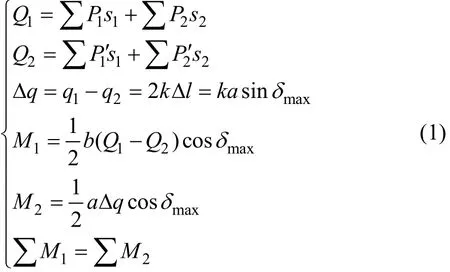
Where1Q and2Q are the composite force of the left boat-type board and the right boat-type board, respectively,N;1P∑ and2P∑ are pressures of the field soil on left boat-type board and left water furrow opener, respectively,Pa;1P′∑ and2P′∑ are pressures of the field soil on right boat-type board and right water furrow opener, respectively,Pa;1s and2s are effective areas of the left and right side of boat-type board and water furrow opener, respectively, m2;a is the length of connecting rod, m; b is the width of boat-type board, m; k is the stiffness coefficient of spring,N/m;maxδ is the maximum tilting angle of boat-type board,(°); q1and q2are pressures of the left and right springs,respectively, N; qΔ is the pressure difference between left and right spring, N; M1is the torque of counter force to the boat-type board produced by field soil, N·m; M2is the torque of counter force to the boat-type board produced by field soil, N·m; lΔ is the maximum compression length of spring, m;1M∑ is the sum of torque of counter force to the boat-type board produced by field soil, N·m;2M∑ is the sum of torque of composite force produced by left and right springs, N·m.
According to field production experience, collapse of the machine is more likely to occur when the tilting angle is 12°-15°. In order to facilitate analysis, the maximum tilting angle of the connecting rod was set to be 15°, meanwhile the ultimate tilting angle of boat-type board was 15°approximately. According to the pressure characteristics of field soil in different depths[18-19], substituted relevant machine size into equations: a is 0.47 m, b is 1.60 m, the effective area of the left and right side of boat-type board s1is 4.60×10⁻²m2, the effective area of the water furrow opener s2is 2.60×10⁻²m2. Then values of parameters about spring are determined by calculating: lΔis 0.06 m, the stiffness coefficient of spring is 1.33×10⁵N/m. In order to meet the machine demand in the actual operation, the stiffness coefficient of selected spring should be larger than this value.
(2) Height profiling mechanism
As shown in Figure 5, the height profiling mechanism mainly consists of fixed slide, slider, and floating block. The mechanism is matched with the transplanter chassis, which can realize the real-time adjustment between the hydraulic system of the transplanter chassis and the working devices of the integration machine. Based on the field topography in the operation, floating blocks would tilt up when the field surface is high-convex, then the slider could be driven to clockwise swing in fixed slide, so that the linked line open commutator and the hydraulic cylinder will be filled into oil,thus seeding and fertilizing device can be hoisted. As a result,the machine and floating block would gradually restore to a state of balance. Similarly, the floating block will tilt down when field surface is low-lying and the seeding and fertilizing device could be fallen down, so that the machine restores to a state of balance. In the field operation, the real-time pressure connection of floating blocks and transplanter chassis hydraulic system is established, so that the grounding pressure of boat-type board fluctuates at a small range, the machine can adapt to the operation condition and ensure the depth consistency of seeding and fertilizing.

Fig.5 Schematic diagram of height profiling mechanism
2.2 Design of fertilization system
The fertilization system mainly includes the sliding and cutting type fertilizer furrow opener, electrical outer slot wheel fertilizer applicator, speed governor, as well as 12 V DC storage battery.
(1) Sliding and cutting type fertilizer furrow opener
1) Design requirements
During the fertilizing process, the furrow opener should open a certain width and depth of fertilizer furrow and manure fertilizer on the bottom of fertilizer furrow. The design of fertilizer furrow opener should meet the following requirements:
① The fertilizer furrow is smooth. In order to meet different fertilizer demands, the fertilizing depth is consistent and adjustable.
② The better ability of entering and cutting mud could guarantee the small resistance, the stable ditching performance, and the furrow opener is not easy to be clogged by soil and stubble.
③ The fertilizer can be guided to the fertilizer furrow and furrow opener has certain ability to cover furrow with mud. The fertilizer can be deeply buried for achieving deep fertilization and improving the utilization rate of fertilizer.
2) Structure design
According to the agronomic requirements of fertilizing,the fertilizer furrow opener adopted the sliding and cutting form, and the cutting edge was designed by curve, which can reduce the ditching resistance[20]. As shown in Figure 6a, the circular curve is used to establish a coordinate system and tangents are made at point A and point B. The 2 points are selected from the edge curve AB. The forward direction of the opener is positive direction of X axis, sliding and cutting angles of point A and point B areAθ andBθ. So point A and point B are initial point and end point of curve,respectively,Aθ is the initial sliding and cutting angle of the curve.
① Edge curve
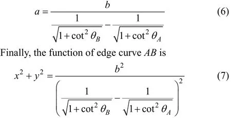
According to the known circular curve, the function of edge curve AB is

Where x is abscissa of edge curve AB, mm; y is ordinate of edge curve AB, mm; a is radius of edge curve AB, mm.
The first order derivative equation of the function is
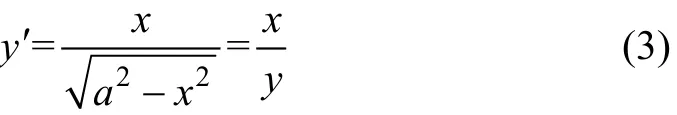
Therefore, the first order derivative equations of point A and point B are (in combination with equation (3))

WhereAx is abscissa of point A, mm;Ay is ordinate of point A, mm.
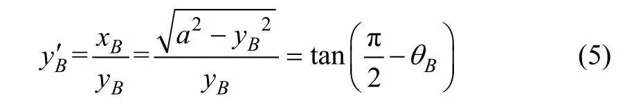

Fig.6 Schematic diagram of sliding and cutting type fertilizer furrow opener
WhereBx is abscissa of point B, mm;By is ordinate of point B, mm.
In the above first order derivation equations, the collation equation can be expressed as follows
Structure parameters of fertilizer furrow opener are shown in Figure 6a and Figure 6b.
② Sliding and cutting angleAθ andBθ
She took care not to be noticed as she reached the ship, and directly she got on board she once more changed to her former lovely appearance and told the prince that her luggage was now all on board, and that they need wait for nothing more
As the maximum internal friction angle ranging from 17° to 19°[21], the initial sliding and cutting angle of point A was determined to be 19°. When fertilizer furrow opener enters into the soil vertically, the effects of sliding and cutting would also be produced, the equations of the sliding and cutting angle of point B are
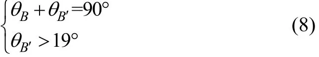
WhereBθ is sliding and cutting angle, (°);Bθ′is coangle ofBθ, (°).
The extent of slip angle of point B is

When the sliding and cutting angle is 35°-55°, the tillage resistance and ditching force of soil is the least circumstance in the process of ditching[22-24], which can meet formula (9), and the sliding and cutting angle of point B is confirmed to be 35°.
③ Edge angle α
When the edge angle is too large, the side wall of furrow opener is prone to make the weeds winding and mud sticking. When the edge angle is too small, the cutting ability of furrow opener is weakened. No matter how the friction angle between soils or between soil and metal changes, the minimum cutting resistance always occurs when the edge angle is close to 45°[25-26], so the edge angle of the furrow opener is determined to be 45°.
④ Furrow width L
As a result of the furrow width having great influence on cutting resistance, the ditching resistance would increase significantly with the increase of furrow width, and the smaller width of furrow can reduce the ditching resistance.According to the agronomic requirements of fertilizing, the furrow width is 50 mm[27-28].
The sideboard of furrow opener is favorable for soil covering the furrow, meanwhile it avoids soil disturbing fertilizer movement track and hill-drop position. The above analysis shows that the furrow width should be reduced, and covering soil angle is 30°[29-31].
Finally, the structure of sliding and cutting fertilizer furrow opener is shown in Figure 6b and 6c.
(2) Design of electrical force outer slot wheel fertilizer applicator
Electrical force outer slot wheel fertilizer applicator drives the structure of single outer slot wheel fertilizer applicator by using a motor, which is composed of the outer slot wheel fertilizer applicator and the electric motor.
1) Structure composition
As shown in Figure 7, the outer slot wheel fertilizer applicator mainly consists of the shell, outer slot wheel,blocking wheel, regulating sleeve, fertilizer-guiding plate,barrier bar, fertilizer-clearing brush, fertilizer baffle, electric motor, and mounting plate. Among them, the electric motor is fixedly connected with the mounting plate at the outer side wall of shell. Outer slot wheel is installed in shell and fixed with the power output shaft of the electric motor. The blocking wheel and mounting plate can prevent fertilizer leaking from two side-walls of shell, and the diameter of blocking wheel is the same with that of outer slot wheel. The regulating sleeve is connected with blocking wheel, which has the thread connection with outer slot wheel, so the working length of outer slot wheel can be changed by adjusting the axial movement of blocking wheel along the outer slot wheel. The fertilizer-clearing brush is installed on the inner and front wall of shell. The fertilizer-guiding plate is mounted on the front position of clearing brush. Top and bottom parts of the guiding plate are closely fitted to clearing brush and connected with baffle bar, respectively.The fertilizer baffle is installed on the inner and back wall of the fertilizing shell.
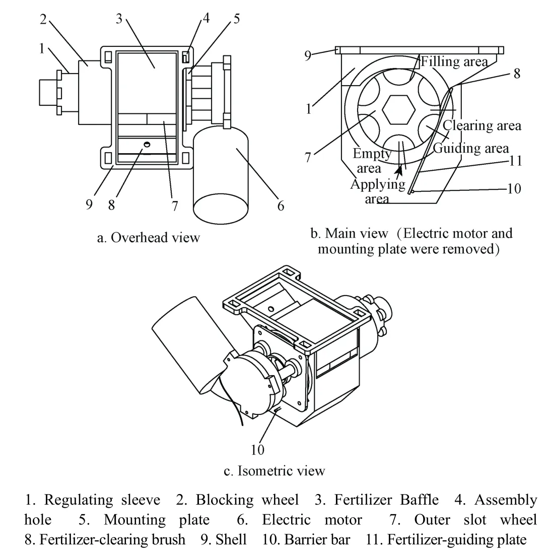
Fig.7 Schematic diagram of electrical force outer slot wheel fertilizer applicator
2) Working process
As shown in Figure 7b, the fertilizer in the shell undergoes the fertilizer-filling, fertilizer-clearing, fertilizerguiding and fertilizer-applying. Forced by the gravity, the fertilizer enters the shell from fertilizer case. The outer slot wheel rotates clockwise when driven by the electric motor.Then the shell fertilizer is forced by its own gravity and the supportive force of outer slot wheel wall, the fertilizer fills outer slot wheel under multiple forces, and finally the fertilizer-filling process is completed. Then some fertilizers may be incompletely located in slot, clearing brush can get excess fertilizer rid of slot, leaving them at the fertilizerfilling area, thus fertilizer-clearing process is completed for meeting requirements of the regulated amount of the fertilizers. The fertilizer would have a certain speed because of outer wheel rotation and effect of clearing brush. In order not to interfere with hill-drop performance of the fertilizer,on the basis of fertilizer-guiding plate, the fertilizer is affected by composite forces of the plate’s supportive force and its own gravity, so that it would move along the plate in a form of particle group. Finally, the fertilizer is manured in the fertilizer furrow, and all the working processes have been completed.
3) Structure design of outer slot wheel
① Analysis of outer slot wheel structure factors affecting fertilizer-filling performance
In the process of fertilizer-filling, we ignore the effect of vibration on this process and assume that fertilizer particle is round spheroid and regular arrangement for simplifying the force analysis. The under-pressure of a fertilizer particle is the sum gravity of all the above fertilizer particles, while lateral pressures to which are ignored. As shown in Figure 8a, the coordinate system was set up. The centroid of the fertilizer particle is zero dot and the normal direction of cross section is x axis.
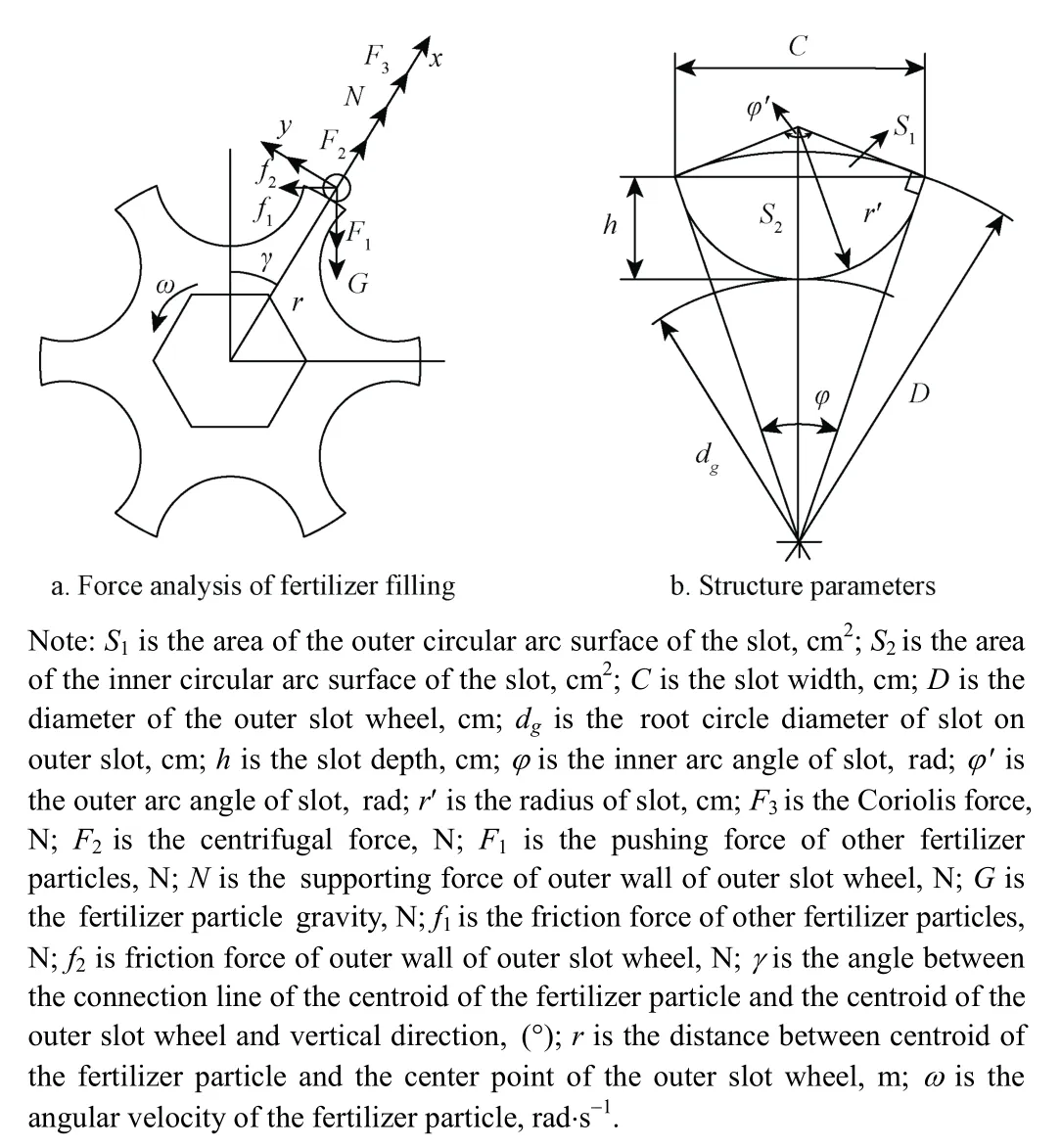
Fig.8 Schematic diagram of outer slot wheel
When outer slot wheel rotates, the fertilizer is driven by outer wall of outer slot wheel and fills slot in fertilizer-filling area. The tangential velocity of the fertilizer particle along outer slot wheel and the tangential velocity of outer wall of outer slot wheel should maintain a certain speed difference for fertilizer filling slot along edge of slot wheel smoothly.As the main factor affecting the fertilizer-filling, if fertilizer-filling time is too long, the fertilizer could not fill slot quickly, resulting in insufficient fertilizer-filling and easy leak-fertilizing. The relationship between the parameter of slot and filling time is investigated when fertilizer-filling.
The fertilizer particle fills slot under its gravity G,centrifugal force F2and coriolis force F3, pushing force of other fertilizer particles F1and supporting force of outer wall of outer slot wheel N, friction force of outer wall of outer slot wheel f2and friction force of other fertilizer particles f1, the mechanical equilibrium equation is established by the decomposition of force system along normal and tangential direction of slot section.
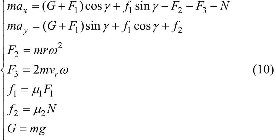
Where m is the weight of a fertilizer particle, kg; axis the normal acceleration of the fertilizer particle, m/s2; ayis the tangential acceleration of the fertilizer particle, m/s2; γ is the angle between the connection line of the centroid of the fertilizer particle and the centroid of the outer slot wheel and vertical direction; r is the distance between centroid of the fertilizer particle and the center point of the outer slot wheel,m; ω is the angular velocity of the fertilizer particle, rad/s; vris the velocity of fertilizer particle relative to the outer wall of the outer slot wheel, m/s; μ1is the friction coefficient between fertilizer particles; μ2is the friction coefficient between the fertilizer particle and outer wall of outer slot wheel.
Equation (11) was obtained from Equation(10)
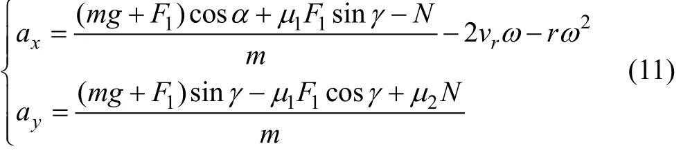
On the basis of analysis of the fertilizer-filling process,the relationship between displacement of a fertilizer particle centroid along normal direction of slot section h (slot depth)and normal acceleration of the fertilizer particle axwas also discussed
Where t is the fertilizer-filling time of fertilizer particle centroid; h is the slot depth, mm.
The combination formula of Equation (11) and Equation (12) can be obtained

It is necessary to shorten the fertilizer-filling time for ensuring that the fertilizer fully fills slot. Based on the analysis of Equation (13), the filling angle γ was set as certain value, fertilizer-filling time is related with design parameters h and r. Taking the first order derivative with factors h and r, the fertilizer-filling time is an increasing function about factor h and a decreasing function about factor r, and thus reducing the value of h, and adding the value of r can effectively reduce fertilizer-filling time.
② Design of structure parameters
Structure parameters of the outer slot wheel are shown in Figure 8b.
Number of slots (z): In order to achieve better performance of fertilizer-filling, the cross section of slot was designed as circular, while outer slot wheel was designed with 6 slots for cooperating with seed-metering device that has 6 dippers, and the synchronization of seeding and fertilizing was realized.
Diameter of outer slot wheel (D): According to the design experience of outer slot wheel, the diameter of outer slot wheel is generally not larger than 60 mm. Considering the relatively little amount of hill-drop fertilization, the designed value of diameter is 50 mm, which is conducive to the uniformity of fertilizing for increasing the pulse frequency and reducing the pulse amplitude effectively.
Radius of slot (r′): Based on analysis of Equation (14),the radius of slot is positively related to the distance between centroid of fertilizer particle and center point of outer slot wheel, so increasing the radius of slot is beneficial to facilitate fertilizer-filling. The radius of slot is 2-9 mm generally by querying the mechanical manuals, and finally the designed value of slot radius is 9 mm.

Where r′ is the radius of slot, cm; r′is the equivalent radius of a fertilizer particle, cm; φ is the inner arc angle of the slot,rad, φ in the tan, (°); D is the diameter of the outer slot wheel, cm.
Depth of slot (h): Based on the analysis of Formula (13),decreasing the depth of slot is good for reducing fertilizer-filling time. At the same time, depth of slot should not be less than half of the maximum axial size of a fertilizer particle, so the designed value of slot depth is 5 mm.
Working length (l): The fertilizer-flowing in the fertilizer distributor is blocked when working length of outer slot wheel is too small. Considering the diameter of slot, the number of slots and the requirement of fertilizing amount,the maximum working length of outer slot wheel was designed to be 50 mm.
The width of slot C and the root circle diameter of outer slot wheel dgcan be determined through calculation, so the design of structure was finished.
Parameters of used fertilizer: The full coefficient of fertilizer is 0.7, the density of fertilizer is 1.735 g/cm3, the designed structural parameters and the maximum working length of the outer slot wheel are substituted to Equation (14)and Equation (15). The maximum fertilizing amount per rotation was calculated to be 35.94 g/r. The required fertilizing amount can be obtained after adjusting the actual working length for meeting the fertilizing requirements of different soil fertility, so the structure parameter design of outer slot wheel is reasonable.

Where, Q is the maximum amount of fertilizing per rotation, g/r; α0is the full coefficient of fertilizer; z is the number of slots in the outer slot wheel; l is the working length of outer slot wheel, cm; γ is the density of fertilizer,g/cm3; S1is the area of the outer circular arc surface of the slot, cm2; S2is the area of the inner circular arc surface of the slot, cm2; S*is the end cross-section area of the slot, cm2;φ ′ is the outer arc angle of slot, rad, φ ′ in the sinφ ′, (°); φ in the sinφ andsin, (°).
4) Electric parts
① Electric motor: It can provide power output for the fertilizer applicator, and adjust the fertilizing amount per unit time by adjusting the speed of fertilizer applicator. The integration machine is driven by transplanter chassis, and the chassis is equipped with 12 V DC (direct current)storage battery. At the same time, fertilizing rotation speed should be matched with that of the seed-metering device,DC motor with speed range of 0-60 r/min was selected, and the size of DC electric motor could meet the space allocation requirements of the machine.
② Governor: DC governor is used to adjust the rotation speed of DC motor, and change rotation speed by adjusting supplying armature voltage. Initial supplying armature voltage is rated, and the rotation speed of DC motor can be smoothly regulated by decreasing supply voltage. To match the design of the integration machine, six-way DC governor was selected, whose speed could be regulated in a stepless way. Since the battery voltage of transplanter chassis is 12 V,the range of working voltage is from 9 to 60 V. The governor should be manually adjusted to zero before speed regulation,and then switched on the power supply voltage.
The circuit connection of the fertilizing system is shown in Figure 9.

Fig. 9 Circuit connection diagram of fertilizer system
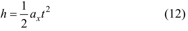
2.3 Seed-metering device
The seed-metering device is a key part of seeding device whose performance directly affects the seeding performance of the integration machine. The machine is equipped with rebound dipper hill-drop precision direct seed-metering device[32]with simple structure and easy adjustment. As shown in Figure 10, seed-metering device consists of the dippers, barrier bar, rotation base, guiding roller, roller shaft, roller frame, seed-throwing tube, torsion spring, seed-clearing brush, seed box and seeding shaft. In the seeding process, the seed is filled by the force of dipper,the seed-clearing is carried out by the brush, the angle energy of torsion spring is stored when the dipper is through the guiding roller, then the dipper gets out of the pressure of guiding roller and contacts with the barrier bar, and thus the seeding process is finally completed. To summarize,through the bench test, hill formation and seed-moving synchronization performance of seeding device was verified,and the test results met seeding agronomic requirements. All these are shown in the reference [22], without repetition here.
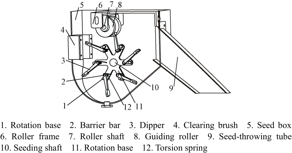
Fig. 10 Structure diagram of rebound dipper direct seed-metering device
3 Field experiment and analysis
3.1 Experiment conditions
On May 2, 2017, the field experiment of precision rice hill-direct-seeding machine and electrical drive side deep hill-drop fertilization machine was carried out in the test base of Northeast Agricultural University in Suihua City,Heilongjiang Province. The water depth was consistent and the soil was smooth after field management, which met the field agronomic requirements of seeding and fertilizing. The varieties of rice and fertilizer used in field experiment were Longqing No.3 and mixed fertilizer for rice, respectively.The seed was soaked and germinated to the extent of bud breaking chest and exposing white part before operation, so the impact of extreme climate on the seedling rate was reduced.
3.2 Experiment methods
NY/T1143-2006 Quality Evaluation and Technical Specifications of Seeder, NY/T987-2006 Operation Quality for Film-covering Hill-drop Direct Seeder and NY/T1003-2006 Quality Evaluation and Technical Specifications were applied as the inspection standard for the field experiment. Such standards use the number of seeds each hill, the seeding hill spacing, the broken bud seed rate, the number of fertilizers each hill, and the fertilizing hill spacing. The above indices of agronomic requirements are shown in Table 2.

Table 2 Standard for field experiment
3.3 Experiment results and analysis
3.3.1 Test data determination
The selected machine’s working parameters in field experiment were in accordance with the optimal performance parameters of seed-metering device. Those were, a 14.4 kW Kubota transplanter chassis providing traction for machine, which had a uniform speed of 2.48 km/h,both seed-metering device and fertilizer applicator were at a rotation speed of 29 r/min, and seeding and fertilizing operations were in stable condition. The machine in the field is shown in Figure 11. We selected one-way operation distance to test the seed-metering devices and fertilizer applicators from No.1 to No.6, and the test distance of 40 m is randomly selected in each of the 6 rows. And 3 groups were measured in the experiment, taking the average value as the final performance index value.
Fig. 11 Integration machine in field experiment
In order to observe the fertilizer state after operation,fertilizer furrow openers were adjusted downwards, and the height of machine was in a suitable condition under the premise of meeting the fertilizing depth, which could avoid supporting board to cover the furrow with mud.
After the field experiment, the results showed that the depth of fertilizer furrow was 50 mm, the lateral distance of fertilizer furrow from bud seed row was 30 mm, the width of fertilizer furrow was 50 mm, and the shape of furrow was smooth, as shown in Figure 12.

Fig.12 Condition of seed and fertilizer after field experiment
3.3.2 Seeding results and analysis
1) Analysis of number of seeds each hill
In accordance with the hill-direct-seeding agronomic requirements for conventional rice, 0-4 seeds each hill is recorded as leak-seeding, 5-8 seeds each hill is recorded as qualification, and more than 8 seeds each hill is recorded as reseeding. With the methods, qualification rate, reseeding rate, leak-seeding rate, and broken bud seed rate of seed-metering devices from No.1 to No.6 were calculated,and final results were shown in Table 3. In each row, the minimum and average values of qualification rate were 85.10% and 86.73%, respectively, while the maximum and average values of the broken bud seed rate were 0.37% and 0.31%, respectively, which met the relevant agronomic requirements of number of seeds each hill.

Table 3 Calculation result of number of seeds each hill
As can be seen from Table 3, from No.1 to No.6, the qualification rate of number of seeds each hill shows a trend of first decreasing and then increasing, while the leak-seeding rate shows a trend of first increasing and then decreasing. The qualification rates of No.3 and No.4 seed-metering devices were lower than those of others,while the leak-seeding rates were higher than those of others.As the sprocket on seeding shaft was placed between the No.3 and No.4, the process of power chain transmission caused vibration. The impact on No.3 and No.4 seed-metering devices was more remarkable than that on others, so some seeds fell off the dipper, thus causing the above results.
2) Analysis of seeding hill spacing
After once seeding of a dipper, the smallest circle that contained all the bud seeds on ridge was selected as an effective seeding hill, so the distance between 2 adjacent centers of 2 effective seeding hills is seeding hill spacing.The seeding hill spacing was measured after operation.Under the predefined standard value of 150 mm, the measured data were statistically analyzed, and the calculation results of seeding hill spacing were obtained, as shown in Table 4.
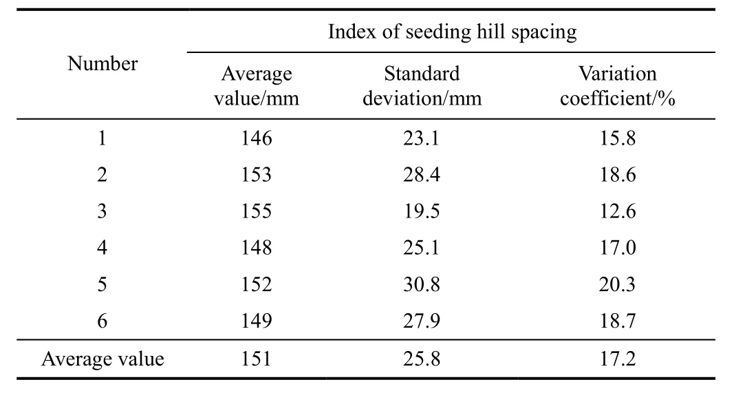
Table 4 Calculation results of seeding hill spacing
According to the method, results shows that the seeding hill spacing of each row ranged from 75 to 225 mm, so the qualification rate of hill spacing was 100%, while the maximum and average values of the variation coefficient were 20.3% and 17.2%, which met the relevant agronomic requirements.
3.3.3 Fertilizing results and analysis
1) Analysis of number of fertilizers each hill
On the basis of hill-drop fertilization requirements for rice hill-direct-seeding, the local soil fertility and the type of used fertilizer, the fertilizing rate per 667 m2was 30-50 kg.The fertilization of fertilizer applicator should be matched with the operation of seed-metering device, so the fertilizing hill spacing was set to be 150 mm, and each hill should fertilize 1.79-2.99 g through calculation. The spherical rate of the fertilizer particle is above 85%, so a fertilizer particle could be approximated as sphere with equivalent radius of 2.16 mm, and the fertilizer densityγis 1.735 g/cm3. The average weight of fertilizer particle is 0.073 g by the way of calculating, so each hill should fertilize 25-41 fertilizer particles. 0-24 fertilizer particles each hill is recorded as leak-fertilizing, 25-41 fertilizer particles each hill is recorded as qualification, and more than 41 fertilizer particles each hill is recorded as re-fertilizing. According to the method,qualification rate, re-fertilizing rate and leak-fertilizing rate of fertilizer applicator from No.1 to No.6 were calculated.Final results were shown in Table 5. The minimum and average values of the qualification rate were 85.88% and 87.49%, respectively, which met the agronomic requirements of number of fertilizers each hill.
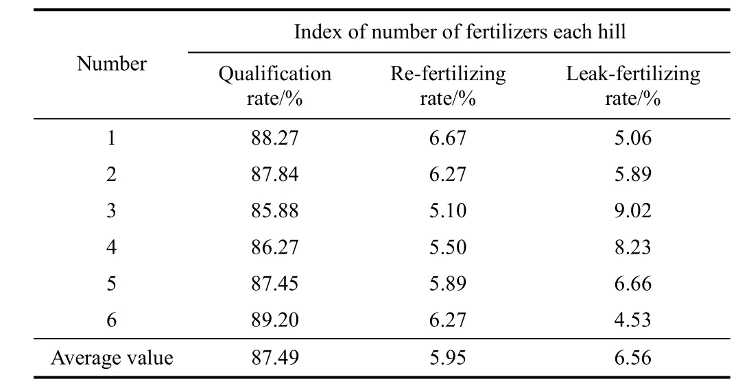
Table 5 Calculation results of number of fertilizers each hill
As can be seen from Table 5, from No.1 to No.6, the qualification rate of number of fertilizers each hill shows a trend of first decreasing and then increasing, and the leak-fertilizing rate shows a trend of first increasing and then decreasing. The qualification rates of No.3 and No.4 fertilizer applicators were lower than those of others, while leak-fertilizing rates were higher than those of others. The above changes of fertilizing were in accordance with changes of seeding. The vibration of chain transmission had more significant impact on the operations of No.3 and No.4 fertilizers, and some fertilizers would fall off the slot, thus causing the above results.
2) Analysis of fertilizing hill spacing
After once fertilizing of a slot, the smallest circle that contained all the fertilizers on the bottom of fertilizer furrow was chosen as an effective fertilizing hill, so the distance between 2 adjacent centers of 2 effective fertilizing hills was fertilizing hill spacing. First the fertilizing hill spacing was set to be 150 mm, and the fertilizing hill spacing was measured after operation. The measured data were statistically analyzed, and the calculation results of fertilizing hill spacing were obtained, as shown in Table 6.
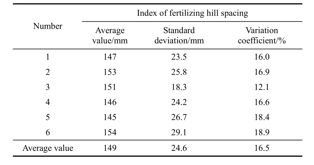
Table 6 Calculation results of fertilizing hill spacing
According to the method, the result shows that the fertilizing hill spacing of each row was in the range of 75-225 mm, the qualification rate of fertilizing hill spacing was 100%, while the maximum and average values of the variation coefficient were 18.9% and 16.5%, respectively,which met the relevant agronomic requirements.
3.4 Fea sibility experiment
According to the rotation speed of the seed-metering device, which was set in the bench test of reference [22], the range of rotation speed in seeding bench test was from 14 to 36 r/min, so rotation speeds of seed-metering device were selected as 5 levels: 15, 20, 25, 30 and 35 r/min; the seeding operation was under the optimal working condition, and fertilizing rotation speeds were matched with seeding rotation speeds. According to the rotation speed levels, all the experiments were conducted one by one. On the basis of the relevant test method, and the average values of indices of all seeding devices or fertilizing applicators as the final performance indices of seeding or fertilizing operation, the final test results were obtained by the statistical analysis. As shown in Table 7, we can see from the test results that all the performance indices met the agronomic requirements, and the feasibility of integration machine was verified.

Table 7 Calculation results of feasibility experiment
4 Discussion and conclusion
4.1 Di scussion
In the field experiment of fertilizing operation, the fertilizer might be adhered to fertilizer applicator because of deliquescence, which affected the fertilizing performance to some extent, but the experiment results could still meet the agronomic requirements. In the process of fertilizing,manual knocking on the fertilizer applicator for some time was needed, so the adhered fertilizer would fall off the applicator for vibration, which promoted the fluxility of the fertilizer in applicator, and cleared up the remained fertilizer in box, and fertilizing device was covered by a tarp after operation, reducing adverse effects to fertilizer fluxility for reducing the possibility of fertilizer deliquescence by wet as far as possible. In the future, the follow-up related research about fertilizer circumstances in the operation and reducing fertilizer deliquescence problem is needed.
4.2 Concl usion
The electrical drive side deep hill-drop fertilization system was developed, which could be matched with precision rice hill-direct-seeding machine. At the same time,a number of operations such as opening furrow, side deep hill-drop fertilization, covering mud, forming ridges and precision rice hill-direct-seeding were realized.
2) The omni-directional profiling system was designed,so the integration machine can be adjusted in real time for adapting to actual working environment in the field, which ensured the qualities of seeding and fertilizing. The fertilizer furrow opener was designed by circular curve. Electrical force outer slot wheel fertilizer applicator was designed, and the structure parameters of outer slot were determined based on the analysis of structure factors affecting the fertilizer-filling performance, and the maximum amount of fertilizing was calculated. The structure meets the design requirements. It is a simple and efficient way of adjusting the fertilizer applicator independently by connecting with electric parts. Thus, the fertilization system was developed.
3) The field experiment of the integration machine was carried out on the optimal operation condition, and the results showed that the qualification rates of number of seeds and number of fertilizers in each hill were 86.73% and 87.49%, respectively. The fertilizing hill spacing could be matched with seeding hill spacing, and the variation coefficients of seeding and fertilizing hill spacing were 17.2% and 16.5%, respectively. The broken bud seed rate was 0.31%. According to the working rotation speed of seed metering device and fertilizer applicator within the range from 14 to 36 r/min, the feasibility experiments were done.The operation performance results could meet the agronomic requirements of precision rice hill-direct-seeding and side deep hill-drop fertilization, which provided a reference for design and evaluation of the integration machine.
[Reference]
[1] Tian Liquan, Wang Jinwu, Tang Han, et al. Design and performance experiment of helix grooved rice seeding device[J]. Transactions of the Chinese Society for Agricultural Machinery, 2016, 47(5): 46-52.
[2] Cheng Jianping, Luo Xiwen, Fan Qizhou, et al. Influence of different planting types on growth and development characteristics and yield of rice[J]. Journal of Huazhong Agricultural University, 2010, 29(1): 1-5.
[3] Zhang Hongcheng, Gong Jinlong. Research status and development discussion on high-yielding agronomy of mechanized planting rice in China[J]. Scientia Agricultural Sinica, 2014, 47(7): 1273-1289.
[4] Rtnayake R M C, Balasoriya B M C P. Re-design fabrication and performance evaluation of manual conical drum seeder a case study[J]. Applied Engineering in Agriculture, 2013,29(2): 139-147.
[5] Yan Xiang. Research the Application Status of Fertilizer and Nutrient Use Efficiency in China[D]. Beijing: Chinese Academy of Agricultural Sciences, 2008.
[6] Zeng Xibo, Li Jumei. Fertilizer application and its effect on grain production in different counties of China[J]. Scientia Agricultural Sinica, 2004, 37(3) :387-392.
[7] Woo S M, Uyeh D D, Sagong M S, et al. Development of seeder for mixed planting of corn and soybeans[J].International Journal of Agricultural & Biological Engineering, 2017, 10(3): 95–101.
[8] Maleki M R, Mouazen A M, De Ketelaerer B, et al. A new index for seed distribution uniformity evaluation of grain drills[J]. Biosystems Engineering, 2006, 94(3): 471–475.
[9] Xia Junfang, Xu Qichuan, Wang Zhishan, et al. Design of rice bud seed sowing and fertilizer machine[J]. Transactions of the Chinese Society for Agricultural Machinery, 2010,41(10): 44-47.
[10] Luo Xiwen, Jiang Enchen, Wang Zaiman, et al. Precision rice hill-drop drilling machine[J]. Transactions of the Chinese Society of Agricultural Engineering (Transactions of the CSAE), 2008, 24(12): 52-56.
[11] Wang Zaiman, Luo Xiwen, Tang Xiangru, et al. Precision rice hill-direct-seeding technology and machine based on the combination of agricultural machinery and agronomic technology[J]. Journal of South China Agricultural University, 2010, 31(1): 91-95.
[12] Zeng Shan, Tang Haitao, Luo Xiwen, et al. Design and experiment of precision rice hill-drop drilling machine for dry land with synchronous fertilizing[J]. Transactions of the Chinese Society of Agricultural Engineering (Transactions of the CSAE), 2012, 28(20): 12-19.
[13] Dong Kehong, An Longzhe, Xu Feng, et al. Design of rice seed sowing and fertilizer machine for cold area[J]. Farm Machinery Using & Maintenance, 2017, 4: 1-2.
[14] Ji Changying, Lv Zhengpan, Qi Xindan, et al. Development of screw pump deep applicator of ammonium bicarbonate for paddy field[J]. Transactions of the Chinese Society of Agricultural Engineering (Transactions of the CSAE), 2002,18(4): 59-63.
[15] Yang Xinlun. Optimization Design and Experiment of Paddy Field Side Deep Fertilizing Device[D]. Harbin: Northeast Agricultural University, 2015.
[16] Chen Xiongfei, Luo Xiwen, Wang Zaiman, et al. Experiment of synchronous side deep fertilizing technique with rice hill-drop drilling[J]. Transactions of the Chinese Society of Agricultural Engineering (Transactions of the CSAE), 2014,30(16): 1-7.
[17] Li Mutong, Wen Xiangyu, Zhou Fujun. Working parameters optimization and experiment of precision hole fertilization control mechanism for intertilled crop[J]. Transactions of the Chinese Society for Agricultural Machinery, 2016, 47(9): 37-43.
[18] Ji Changying, Lu Zhixiong, Pan Junzheng. Analysis of Bearing Capacity and Adhesion to Solid Surfaces of Paddy Soil[D]. Nanjing: Journal of Nanjing Agricultural University,1999, 22(4): 105-108.
[19] Liu Yi. Soil Traffickability Study Based on Mechanical Properties of Paddy Soil[D]. Nanjing: Nanjing Agricultural University, 2014.
[20] Zhao Shuhong, Liu Hongjun, Zhang Xianmin. Design and optimization experiment of working performance of sliding push opener[J]. Transactions of the Chinese Society of Agricultural Engineering (Transactions of the CSAE), 2016,32(19): 26-34.
[21] Zhang Rui, Wang Xiu, Zhao Chunjiang, et al. Design and experiment of variable rate fertilizer spreader with conveyor chain[J]. Transactions of the Chinese Society of Agricultural Engineering (Transactions of the CSAE), 2012, 28(6): 20-25.
[22] Gu Yaoquan, Jia Honglei, Guo Hui, et al. Design and experiment of sliding knife furrow opener[J]. Transactions of the Chinese Society for Agricultural Machinery, 2013, 44(2):38-42.
[23] Qi Xingyuan, Zhou Zhiyan, Yang Cheng, et al. Design and experiment of key parts of pneumatic variable-rate fertilizer applicator for rice production[J]. Transactions of the Chinese Society of Agricultural Engineering (Transaction of the CSAE), 2016, 32(6): 20-26.
[24] Geng Xiangyu, Li Yanming, Miao Yubin, et al. Development of variable rate fertilizer applicator based on GPRS[J].Transactions of the Chinese Society of Agricultural Engineering (Transactions of the CSAE), 2007, 23(11): 164-167.
[25] Fulton J P, Shearer S A, Chabra G, et al. Performance assessment and model development of a variable-rate,spinner-disc fertilizer applicator[J]. Transactions of the ASAE, 2001, 44(5): 1071-1081.
[26] Zuo Xingjian, Wu Guangwei, Fu Weiqiang, et al. Design and experiment on air-blast rice side deep precision fertilization device[J]. Transactions of the Chinese Society of Agricultural Engineering (Transactions of the CSAE), 2016,32(3): 14-21.
[27] Kumar G V P, Srivastava B, Nagesh D S. Modeling and optimization of parameters of flow rate of paddy rice grains through the horizontal rotating cylindrical drum of drum seeder[J]. Computers and Electronics in Agriculture, 2009,65(1): 26–35.
[28] Chen Shufa, Zhang Shiping, Sun Xingzhao, et al. Design and experiment of self-propelled high-groud-clearance spreader for paddy variable-rate fertilization[J]. Transactions of the Chinese Society of Agricultural Engineering (Transactions of the CSAE), 2012, 28(11): 16-21.
[29] Xiao Hongru, Zhao Ying, Ding Wenqin, et al. Design and experiment on blade shaft of 1KS60-35X type orchard double-helix trenching and fertilization machine[J].Transactions of the Chinese Society of Agricultural Engineering (Transactions of the CSAE), 2017, 33(10): 32-39.
[30] Fu Qiankun, Jian Shichun, Jia Honglei, et al. Design and experiment on maize stubble cleaning fertilization ridging seeder[J]. Transactions of the Chinese Society of Agricultural Engineering (Transactions of the CSAE), 2016, 32(4): 9-16.
[31] Yuan Yanwei, Li Shuwei, Fang Xianfa, et al. Decision support system of N, P and K ratio fertilization[J].Transactions of the Chinese Society for Agricultural Machinery, 2013, 44(8): 240-244.
[32] Tian Liquan, Tang Han, Wan Jinwu, et al. Design and experiment of rebound dipper hill-drop precision direct seed-metering device for rice[J]. Transactions of the Chinese Society for Agricultural Machinery, 2017, 48(4): 44-47.
猜你喜欢
青少年科技博览(中学版)(2022年6期)2022-12-27
农业工程学报(2022年6期)2022-06-27
农业工程学报(2022年6期)2022-06-27
军事文摘(2021年22期)2021-11-26
农机科技推广(2021年3期)2021-08-02
文苑(2020年6期)2020-06-22
文苑(2019年22期)2019-12-07
建材发展导向(2019年10期)2019-08-24
中国交通信息化(2019年6期)2019-08-23
电子制作(2018年10期)2018-08-04