
Numerical and experimental studies of hydrodynamics of flapping foils *
2018-05-14 01:42KaiZhou周凯JunkaoLiu刘军考WeishanChen陈维山
水动力学研究与进展 B辑 2018年2期
关键词:刘军
Kai Zhou (周凯), Jun-kao Liu (刘军考), Wei-shan Chen (陈维山)
1. College of Mechanical and Electronic Engineering, Shandong Agricultural University, Taian 271018, China
2. State Key Laboratory of Robotics and System, Harbin Institute of Technology, Harbin 150001, China
Introduction
The conventional screw propellers have the disadvantages of low efficiency, poor maneuvering performance, and large noise , which greatly limit their applications in narrow, complex and dynamic environments. However, after millions of years of evolution,creatures are capable of swimming or flying with high speed and efficiency. Therefore, the biomimetic propulsor attracts research attentions[1].
Most fast-swimming creatures undulate their fins to obtain thrust. Similarly, flying creatures undulate their wings to resist gravity and move forward. They have similar characters in shape and motion mode, in reducing resistance and obtaining valuable force. The flapping foil based on bionics is a sort of simplified models, which can imitate the motion of the wings or fins of fish and birds[2-6]. With different motion parameters, the hydrodynamic performance varies correspondingly. In addition, a simple imitation of motion is not enough, its mechanism is a more important issue.The hydrodynamic mechanism would provide a theoretical reference for the design of underwater vehicles based on the flapping propulsion.
In the movements of fish and birds, one sees the symmetric mode and the asymmetric mode. Most fish flap their caudal fins in the symmetric mode, with equal forces generated from both the upstroke and down stroke. On the other hand, with an oscillation parallel to the advance direction, the asymmetrical mode consists of a powerful down stroke generating large force and a weak upstroke with a weak force, as evidenced by the motion patterns of turtles and birds[7-11].
The symmetric mode and the asymmetric mode were usually studied separately, focusing on certain bionic prototypes, lack of generality. The kinematic parameters of living fish, birds and bionic robots were widely studied, but without enough attention to the hydrodynamic mechanism. In this paper, a united motion model containing the symmetric mode and the asymmetric mode is developed. By analyzing the flow field generated in the process of flapping and forcing of the foil, the propulsion mechanism of the bionic foil is studied. And then the influence of the motion parameters on the hydrodynamic performance of the bionic foil is analyzed. The simulation results are compared with the existing related studies to assess the reliability of the numerical method. In addition, an experimental method is adopted to further validate the numerical approach.
1. Materials and methods
1.1 Geometric model
Based on observations of fish and birds, the sections of fins or wings parallel to the flow direction take streamlined shapes, similar to the NACA airfoils.Thus the hydrodynamic force can be viewed as the resultant force of a series of forces acting on the streamlined sections. In this paper, the NACA0013 airfoil is chosen to construct the section. Figure 1 presents the geometry of the three-dimensional model,wherec=0.1m is the chord length,L=0.3m is the length along the span direction, andOis the reference point.Ois located 0.25cfrom the leading edge and the projected area (one-sided)Sis 3.2×10⁻²m2. The foil makes a periodic motion along the vertical direction and the horizontal direction,meanwhile, the foil makes a pitching movement around the reference axis.
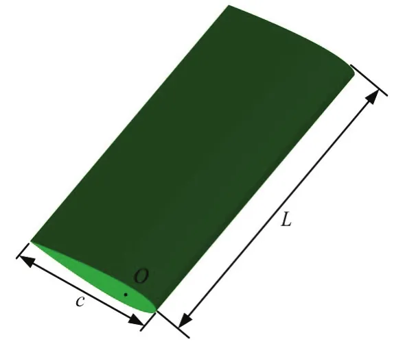
Fig.1 (Color online) Geometric model of the foil
1.2 Motion model
In this study, the foil is allowed to move with three degrees of freedom. Specifically, the foil is towed forward at a constant speedUand there are three types of movements: the heave motion transverse to the direction of towing, the angular motion around a span wise axis, and the surge motion parallel to the direction of towing. The motion of the foil can be described by the following equations:


wherefis the flapping frequency,tis the time,and β is the stroke angle[12]. In contrast to the traditional symmetric motion model,x(t) is adopted to describe the oscillatory motion parallel to the forward direction. With the stroke angle β, different trajectories can be formed to represent different motion models of different bionic prototypes. As shown in Fig.2, the case of β=45° describes the motion mode of birds. It can be seen that birds direct their wings forward during the down stroke, creating a highly asymmetric flap to generate a net lift force. The case of β=90° describes the motion mode of fish.In the symmetric mode, a symmetric trajectory is formed without the surge motion parallel to the direction of towing. The case of β=135° describes the motion mode of turtles. It can be seen that turtles direct their flippers backward during the down stroke,creating a highly asymmetric flap to generate a net trust force.
In addition, the pitching angle θ is given by

where
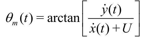
The angle α(t) is the angle of attack. In the case of β =90°

and in the case of β≠90°


The anglemθ represents the tangential direction of the trajectory, and the angle of attack α(t) is also an independent variable. The definition makes it easier to develop an optimization method for the motion trajectory or the angle of attack. In the nature, fish and birds adjust the angle of attack and the trajectory constantly to eliminate the unwanted forces and keep the speed and the efficiency at a high level.
1.3 Numerical method
Using the commercial software Fluent (ANSYS Inc., Canonsburg, USA), the governing equations are discretized by the finite volume method (FVM) with a first-order discretization in the time and a second order discretization in the space. The fluid motion is computed based on an unstructured, tetrahedral grid.The simulation is a dynamic process and the boundaries of the foil are changing constantly. Therefore,in this paper, the dynamic mesh method is adopted to deal with the moving boundary problem. The motion of the foil is realized through user-defined functions(UDFs) linked to the Fluent. In the calculation, the SIMPLE method of the pressure-speed amending method and thek-εturbulence mode are adopted.
The simulations start from the static state of the foil, and then the foil moves according to the motion model. The cubic computational domain (2.5 m×1.2 m×1.2 m) is discretized into 8.1×10⁵grid cells.Besides, refined meshes are used near the boundaries of the foil. To verify the grid in dependency, the simulation with a mesh of smaller cell size is carried out and only a difference of 4% between the coarse grid and the fine grid is found.
To evaluate the hydrodynamic performance of the foil, the force and the torque acting on the foil are extracted and converted to dimensionless forms:
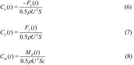
where ρ is the density of the fluid,Fyis the transverse force, -Fxis the thrust force,Mθis the torque, andSis the projected area of the foil. The propulsive efficiency η is defined as the ratio of the output poweroPto the input powereP, which can be defined as:
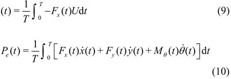
whereTis the period of the motion. The chord Reynolds number and the Strouhal numberStare defined as:
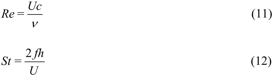
where ν is the fluid kinematic viscosity.
2. Experiment approach and setup
With the developments of computer technology and computational fluid dynamics (CFD), numerical methods are having more and more extensive applications. Compared with the traditional experimental method, the numerical method has the advantage of high repeatability, great maneuverability, and less input requirement. Moreover, it is easier to obtain the details of the flow field with the numerical method,thus, many difficulties of measurement in the experimental method can be avoided. Therefore, the numerical method becomes an important method in the mechanism research. However, due to the limitations of the theoretical model, the reliability of the numerical results still needs to be improved. In addition, the computation parameters of the numerical models need to be modified and confirmed according to the experimental results. So usually both the numerical method and the experimental method are adopted in studies.
To validate the reliability of the numerical method used in this paper, an experiment platform is designed and the verification experiments are carried out. Figure 3 shows the design schematic diagram of the experiment platform.
To realize the movements of three degrees of freedom, three servo motors equipped with reducers are used. The synchronous belt transmission is adopted in the towing direction and the gear-gear stripe transmission is adopted in the heave direction.All servo motors are controlled by computer.

Fig.3 (Color online) Design schematic diagram of the experiment platform
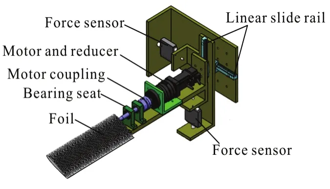
Fig.4 (Color online) Measuring module of the experiment platform

Fig.5 (Color online) Actual photo of the experiment platform
Except the power module and the transmission module, the measuring module is an important part of the system. As is shown in Fig.4, two slide rails are installed on the moving platform along the heave direction. The force sensors act as the transmission components to supply power. According to the mechanical analysis of the moving platform in the horizontal plane, there are the hydrodynamic force,the frictional force, the traction force and the inertia force. Because the coefficients of friction of the slide rails are very small, the frictional force can be ignored.The inertia force can be calculated through the motion equations. The traction force can be provided by the force sensor. Through mathematical calculations, the hydrodynamic force acting on the foil can be obtained.Figure 5 shows the actual photo of the experiment platform.
3. Results
Firstly, for comparing with the existing related studies[13, 14], the motion parameters of the foil are selected as follows:Re=11000,St=0.3,h=c=0.055 m, αmax=25° and the stroke angle β=45°,90° and 135°. Figure 6 shows the force coefficients at different stroke angles.
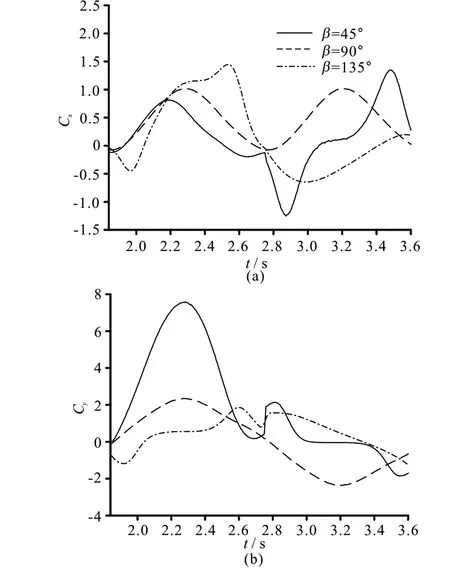
Fig.6 Force coefficients at different stroke angles
The curves see a periodic behaviour, and the curves in a cycle are shown in Fig.6. In the case of β =90°, the curve of the thrust force coefficient has the same shape in the upstroke and the down stroke because of the symmetrical motion. Note that the mean value ofCx, which is equal to 0.58, is positive,while the mean value ofCyis almost zero. In other words, the foil obtains the thrust force without the net transverse force. In the case of β=45°, one sees small fluctuations at the beginning and the end of the upstroke when the foil rotates quickly. The mean thrust force coefficient is 0.21 and the mean transverse force coefficient is 2.12. In the case of β=135°, the mean thrust force coefficient in a cycle is 0.12. In the cases of β=45° and β=135°, the mean transverse forces are not equal to zero because of the asymmetrical motion. In the case of β=45°, it is the transverse force that increases significantly rather than the thrust force. The thrust force in the case of β =135° is relatively small because of the negative mean thrust force of the upstroke, and other experiments show similar phenomena during the upstroke,called “the memory effects” in the wake[13]. Besides,the propulsive efficiency of symmetrical mode is about 47.0% which is well within the range of fish.The propulsive efficiency in the case of β=45° is equal to 11.3%, which is low because the for wards biased flap increases the transverse force significantly rather than the thrust force. The propulsive efficiency in the case of β=135° case is equal to 31.0%,which is also relatively low because of the unwanted energy expenditure during the upstroke.
Figure 7 shows the vortex pattern in the wake. It can be seen that there are vortex rings in the wake,which is similar to the wake of fish and birds. The jet stream can be induced among the vortex rings and the foil obtains a reaction force correspondingly. Specifically, Figure 7(a) shows the 3-D vortex pattern in the case of β=90°. The vortex rings consist of a train of inverted hairpin-like vortices braided together such that the legs of each vortex are attached to the head of the preceding vortex. The vortex structure is similar to those found in the nature and the simulations in other studies[15-18]. Figures 7(b), 7(c) show the comparisons of the vortex patterns in different motion modes viewed fromzdirection. It is shown that the vortex patterns of the asymmetrical mode are characterized by irregular and discontinuous structures. As a result,because of the asymmetrical motion , a net transverse force is produced and more useless energy is expended.
In the nature, birds direct their wings forward during the down stroke, creating a highly asymmetric flap that can generate a net lift force to support the weight. Turtles direct their flippers backward during the down stroke, creating a highly asymmetric flap that can reduce the oscillatory force. The fins of fish can form a symmetric trajectory without the surge motion parallel to the direction of towing and keep a high propulsive efficiency. In the following parts, the influence of the motion parameters on the hydrodynamic performance is analyzed. For comparing with the experimental results, the chord length is chosen to be 0.1 m and the length along the span direction is 0.3 m. The other parameters are selected as follows: αmax=25°,h=0.05m,U=0.2 m/s ,St=0.3. The force coefficients represent the mean value in a cycle.
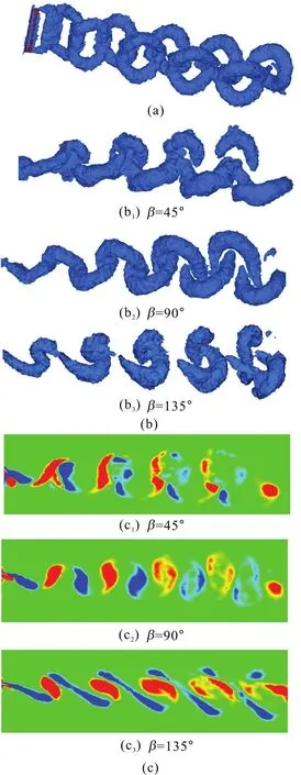
Fig.7 (Color online) Vortex patterns for different stroke angles
3.1 Influence of the angle of attack
To study the influence of the angle of attack, its value is chosen to vary from 10° to 45°. The definition of the angle of attack is different in the symmetric and asymmetric modes, so the influence of the angle of attack for different stroke angles should be analyzed,separately. Figures 8-10 show the mean force coefficients and the propulsive efficiency of the foil with different stroke angles. In the symmetrical mode,the mean thrust force keeps a relatively large value when the angle of attack αmaxvaries from 20° to 30°,as is consistent with fish in the nature. Furthermore, as the angle of attack increases, the mean thrust force increases correspondingly and reaches the peak point,then starts to decrease. Besides, it is found that the propulsive efficiency sees a similar trend as compared with the mean thrust force. Larger or smaller αmaxwill bring a large transverse force and a reduced thrust force, and then decrease the propulsive efficiency. In the case of β=45°, the trajectory of the down stroke is more gradual than in other cases, so large αmaxadopted in the powerful down stroke can increase the transverse force significantly and have little effect on the thrust force. As a result, the propulsive efficiency decreases significantly. In contrast, in the case of β= 135°, the trajectory of the down stroke is steeper,so large αmaxis allowed to keep the thrust force.However, the strong angular motion with a large αmaxwill increase the useless energy consumption, to reduce the propulsive efficiency.
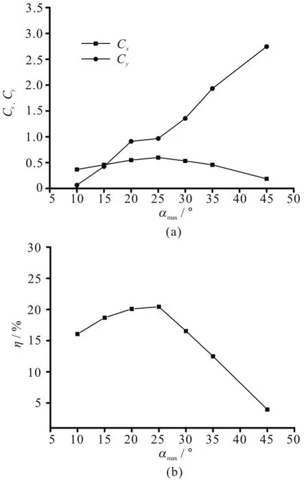
Fig.8 Performance curves against αmax with β=45°

Fig.9 Performance curves against αmax with β=90°
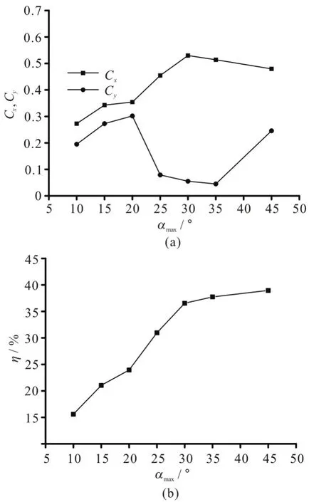
Fig.10 Performance curves against αmax with β=135°
3.2 Influence of the stroke angle
The performance curves against the stroke angle are shown in Fig.11. The dotted lines in Fig.11 represent the values in the case of β=90°. It is shown that the stroke angle greatly affects the hydrodynamic performance of the foil. By choosing a large stroke angle, the foil can obtain a large thrust force with a small transverse force. In contrast, with a small stroke angle, the foil can obtain both a large transverse force and a large thrust force, but the propulsive efficiency is relatively low. In addition, a stroke angle around 90° can achieve a smaller thrust force with a high propulsive efficiency. However, in the symmetrical mode, a higher efficiency can be achieved as com-pared with the asymmetrical mode. A reasonable stroke angle should be adopted in different engineering applications.

Fig.11 Performance curves against stroke angles
3.3 Influence of the heave motion
Here, the case of β=90° is chosen as a typical example to show the influence of the heave motion on the hydrodynamic performance. Figure 12 shows the force coefficients and the propulsive efficiency versus the amplitude of the heave motion. The Strouhal number is chosen to be 0.3 to keep a high efficiency.It is shown that the impact of the amplitude on the mean thrust force is small. Note that the propulsive efficiency reaches the peak value aroundh/c≈ 0.8.As is known, a large heave motion obviously will lead to a large thrust force but a larger heave motion will lead to a lower frequency to keep the Strouhal number constant. So the change of the mean thrust is insignificant when the amplitude of the heave motionhincreases.

Fig.12 Performance curves against amplitudes of heave motion
3.4 Influence of Strouhal number
The Strouhal number is an important parameter in the biological swimming. Furthermore, most fish are shown to swim near a “universal” optimal valueSt=0.3 because of the high propulsive efficiency[19,20].Figure 13 shows the performance curves against the Strouhal number when β=90°. Here, the frequency is chosen to vary to obtain different Strouhal numbers. It is shown that the propulsive efficiency keeps a relatively large value within the range of 0.2-0.4, as is consistent with the range of fish in the nature. Furthermore, a large Strouhal number can lead to a large thrust force, but the transverse force increases correspondingly.
Figure 14 shows the vortex pattern in the wake for different values ofStwhen β=90°. At a low value ofSt, the 3-D structure of the wake is a single and continuous vortex ring. At a high value ofSt, a more complex and laterally diverging structure is observed in the wake. Smaller-scale vertical structures attaching to the hairpin vortices are observed in the wake. The energy dissipation is greater in this case, so the propulsive efficiency is lower at a high value ofSt.In addition, the more complex and laterally diverging structure impacts the transverse force and a considerable net transverse force is produced. The results of asymmetric motion models are similar to those of symmetric motion models.
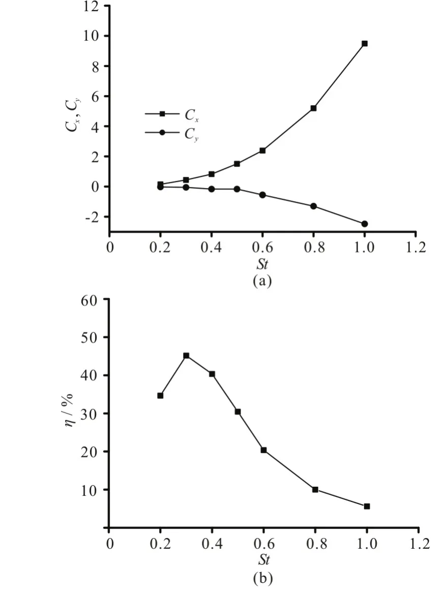
Fig.13 Performance curves against Strouhal numbers

Fig.14 (Color online) Performance curves against amplitudes of heave motions
3.5 Experimental results
To validate the reliability of the numerical method used in this paper, verification experiments are carried out. Table 1 shows the numerical results and experimental results with same parameters. Figure 15 shows the photo of the experiment site. The selected motion parameters of the foil are as follows:Re=20000,St=0.3,h=0.05 m and αmax=25°.Through a comparison, it is found that the present results compare well with those in the previous studies.Therefore, the adopted numerical method is reliable.
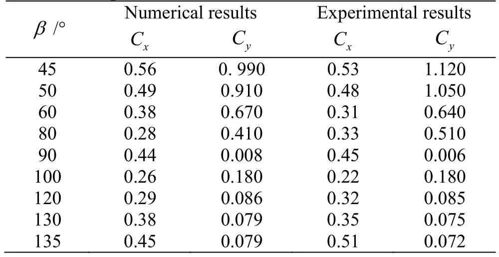
Table 1 Comparison of results

Fig.15 (Color online) Photo of experiment site
4. Conclusions
In this paper, a universal kinematic model with three degrees of freedom is adopted. The motion parallel to the flow direction considered in the model can produce trajectories of different prototypes. Based on this kinematic model, numerical simulations of the flapping foil with different trajectories are conducted.In certain parameter ranges, the mean thrust forces of different motion modes in a cycle could have positive values, that is, the foil can obtain a thrust force. And the propulsive efficiency of the symmetric motion model is significantly greater than those of the asymmetric motion models. In addition, the influences of the motion parameters are analyzed. It is found that the motion parameters play important roles in the hydrodynamic performance of the flapping foil.Besides, to validate the reliability of the numerical method, an experiment platform is designed and verification experiments are carried out. The consistence between the numerical results and the experimental results indicates that the numerical method of the flapping foil is reasonable.
The results can help the bionic propulsor design and improvement. Furthermore, through a reasonable optimization algorithm of the motion parameters, the flapping foil can either reduce the oscillatory force or increase the thrust force and the propulsive efficiency.The optimization algorithm will be completed in the later work.
Acknowledgement
This work was supported by the State Key Laboratory of independent topics, Harbin Institute of Technology (Grant No. SKLRS200801C).
[1] Wu T. Y. Fish swimming and bird/insect flight [J].Annual Review of Fluid Mechanics, 2011, 43: 25-58.
[2] Tang C., Lu X. Y. Self-propulsion of a three-dimensional flapping flexible plate [J].Journal of Hydrodynamics,2016, 28(2): 1-9.
[3] Han R., Zhang J., Cao L. et al. Propulsive performance of a passively flapping plate in a uniform flow [J].Journal of Hydrodynamics, 2015, 27(4): 496- 501.
[4] Hu J., Xiao Q. Three-dimensional effects on the translational locomotion of a passive heaving wing [J].Journal of Fluids and Structures, 2014, 46: 77-88.
[5] Cheng H. Y., Long X. P, Ji B. et al. Numerical investigation of unsteady cavitating turbulent flows around twisted hydrofoil from the Lagrangian viewpoint [J].Journal of Hydrodynamics, 2016, 28(4): 709-712.
[6] Liu W., Li N., Zhao J. et al. Wake structure and hydrodynamic performance of flapping foils mimicking fish fin kinematics [J].Saudi Journal of Biological Sciences, 2017,24(6): 1344-1354.
[7] Szymik B. G., Satterlie R. A. Changes in wing stroke kinematics associated with a change in swimming speed in a ptero pod mollusk, Clione limacine [J].The Journal of Experimental Biology, 2011, 214(23): 3935-3947.
[8] Licht S. C., Wibawa M. S., Hover F. S. et al. In-line motion causes high thrust and efficiency in flapping foils that use power down stroke [J].The Journal of Experimental Biology, 2010, 213(1): 63-71.
[9] Tobalske B. W., Warrick D. R., Clark C. J. et al. Three dimensional kinematics of hummingbird flight [J].The Journal of Experimental Biology, 2007, 210(13):2368-2382.
[10] Dileo C., Deng X. Design of and experiments on a dragonfly-inspired robot [J].Advanced Robotics, 2009, 23:1003-1021.
[11] Berg A. M., Bie wener A. A. Wing and body kinematics of takeoff and landing flight in the pigeon (Columba livia) [J].The Journal of Experimental Biology, 2010, 213(10):1651-1658.
[12] Lindhe Norberg U. M., Winter Y. Wing beat kinematics of a nectar-feeding bat, Glossophaga soricina, flying at different flight speeds and Strouhal numbers [J].The Journal of Experimental Biology, 2006, 209(19): 3887-3897.
[13] Izraelevitz J. S., Triantafyllou M. S. Adding in-line motion and model-based optimization offers exceptional force control authority in flapping foils [J].Journal of Fluid Mechanics, 2014, 742: 5-34.
[14] Zhou K., Liu J., Chen W. Numerical study on hydrodynamic performance of bionic caudal fin [J].Applied Sciences-Basel, 2016, 6(1): 15.
[15] Xia D., Chen W., Liu J. et al. The three-dimensional hydrodynamics of thunniform swimming under self-propulsion [J].Ocean Engineering, 2015, 110: 1-14.
[16] Bhalla A. P. S., Griffith B. E., Patankar N. A. A forced damped oscillation framework for undulatory swimming provides new insights into how propulsion arises in active and passive swimming [J].PLOS Computational Biology,2013, 9(6): e1003097.
[17] Neveln I. D., Bale R., Bhalla A. P. S. et al. Undulating fins produce off-axis thrust and flow structures [J].Journal of Experimental Biology, 2014, 217(2): 201-213.
[18] Bhalla A. P. S., Bale R., Griffith B. E. et al. A unified mathematical framework and an adaptive numerical method for fluid–structure interaction with rigid, deforming, and elastic bodies [J].Journal of Computational Physics, 2013, 250: 446-476.
[19] Taylor G. K., Nudds R. L., Thomas A. L. R. Flying and swimming animals cruise at a Strouhal number tuned for high power efficiency [J].Nature, 2003, 425: 707-711.
[20] Thomas A. L. R., Taylor G. K., Srygley R. B. et al.Dragonfly flight: Free-flight and tethered flow visualizations reveal a diverse array of unsteady lift-generating mechanisms, controlled primarily via angle of attack [J].Journal of Experimental Biology, 2004, 207(24):4299-4323.
猜你喜欢
大众文艺(2022年10期)2022-06-08
童话王国·文学大师班(2022年4期)2022-05-29
学校教育研究(2020年18期)2020-10-26
中国畜牧业(2018年22期)2018-11-28
水动力学研究与进展 B辑(2018年5期)2018-10-27
中国畜牧业(2018年1期)2018-01-11
书画世界(2017年11期)2017-12-29
爱你(2017年35期)2017-11-24
爱你·健康读本(2017年12期)2017-04-09
中国畜牧业(2016年21期)2016-02-18

- 水动力学研究与进展 B辑的其它文章
- Numerical analyses of ventilated cavitation over a 2-D NACA0015 hydrofoil using two turbulence modeling methods *
- Couple stress fluid flow in a rotating channel with peristalsis *
- 2-D eddy resolving simulations of flow past a circular array of cylindrical plant stems *
- Revisit submergence of ice blocks in front of ice cover-an experimental study *
- Energy dissipation of slot-type flip buckets *
- Some notes on numerical simulation and error analyses of the attached turbulent cavitating flow by LES *