
Effects of Froude number and geometry on water entry of a 2-D ellipse *
2018-09-28 05:34XuZhang张旭PeiqingLiu刘沛清QiulinQu屈秋林RuiWang王睿RameshAgarwal
水动力学研究与进展 B辑 2018年4期
Xu Zhang (张旭), Pei-qing Liu (刘沛清), Qiu-lin Qu (屈秋林), Rui Wang (王睿), Ramesh K. Agarwal
1. School of Aeronautic Science and Engineering, Beihang University, Beijing 100191, China
2. School of Engineering and Applied Science, Washington University in St. Louis, St. Louis, USA
Abstract: By using the finite volume method with volume of fluid model and global dynamic mesh technique, the effects of Froude number and geometry on the water entry process of a 2-D ellipse are investigated numerically. For the time history of the vertical force, the computational fluid dynamics (CFD) results match the experimental data much better than the classical potential-flow theories due to the consideration of the viscosity, turbulence, surface tension, gravity, and compressibility. The results show that the position of peak pressure on ellipse shifts from the spray root to the bottom of ellipse at a critical time. The critical time changes with the geometry and Froude number. By studying the vertical force, the ellipse water entry process can be divided into the initial and late stages based on the critical dimensionless time of about 0.1. The geometry of the ellipse plays a dominant role in the initial stage,while the Froude number is more important in the late stage of entry. The classical Wagner theory is extended to the ellipse water entry, and the predicted maximum value of vertical force coefficient in the initial stage is 4πa/ b that matches the CFD results very well, where a and b are the horizontal axis and vertical axis of the ellipse parallel and perpendicular to the initial calm water surface, respectively.
Key words: Water impact, water entry, fluid-structure interaction, Froude number
Introduction
When an object enters into the water, an extremely large load with a heavily impulsive pressure on the body happens, which may result in large damage.Therefore, in the design of missiles, seaplanes, aircraft,spacecraft and marine structures etc.[1-8], the water entry problem has been widely investigated[9-11].
Many parameters affect the water entry process,such as bodyʼs geometry, impact velocity, and initial water surface condition. Previous investigations have generally focused on the vertical entry into initially calm water of an axisymmetric or a 2-D body with a constant speed. The water impact problem was first studied by von Kármán who employed the momentum conservation law and added mass concept to solve the 2-D wedge water entry problem. Later, considering the effect of water splash-up and making the assumption of expanding flat plate, Wagner proposed an improved solution to the 2-D wedge water entry problem and thus extended the work of von Kármán.For the water entry problem of a 2-D circular cylinder,the matched asymptotic expansion method was used by Cointe and Armand, Oliver[12], and Korobkin[13].Zhao et al. used the nonlinear boundary element method to obtain the water surface elevation and the pressure distribution on a 2-D wedge and on a bow flare section entering into the initially calm water. Mei et al. used an analytic method to study the water entry of 2-D wedge, circular cylinder and bow flare section.Greenhow and Sun and Faltinsen[14]used the boundary element method, while Vandamme et al.[15]used the smooth particle hydrodynamics (SPH)method to solve the water entry problem of a 2-D circular cylinder. Most of these studies have focused on the water entry of a 2-D wedge, circular cylinder and bow flare section, and only few on the water entry of ellipse. Schnitzer proposed an approximate method for computing the water impact loads and pressure distribution on bodies approximating elliptical cylinders during oblique water impacts. The effect had concentrated on the pressure distribution. However,the technique showed rough agreement with the test data for 2-D drops of a rigid cylinder. In addition, the water surface elevation was not obtained and the effect of ellipse geometry was not studied. Therefore,it is necessary to study water entry of different geometry of ellipse, because the geometry of the bodies is different in practice.
In the water entry problem, the viscosity, gravity,surface tension, and compressibility all may be important. The surface tension has an effect on the jet flow separation. Zhu et al.[16]stated the compressibility can be neglected, however, the viscosity and gravity should be considered in the late stage of water entry because the viscosity is important for the flow separation and the gravity plays a vital role in the total vertical force when the body enters deep into the water.
1. Description of the physical problem
The sketch of the vertical water entry of a 2-D ellipse is shown in Fig. 1. The origin of the global Cartesian coordinate system is located at the initial water surface. The x-axis points rightwards horizontally, and the y-axis points upwards vertically through the ellipse center. The time variable is t, and the instantaneous speed of the ellipse is v, which is positive when the ellipse moves downwards. The time when the ellipse impacts the initial water surface is defined as t0, and V0denotes the speed of the ellipse at this time. For the water entry of ellipse at a constant speed V, v=V0=V. The immersion depthis the vertical distance between the lowest point of ellipse and the initial water surface. The gray region is full of water, of which the density and the viscosity are 998.2 kg/m3and 1.01×10⁻³Pa·s,respectively. The rest of the region outside the ellipse is full of air, of which the density and the viscosity are 1.225 kg/m3and 1.79×10⁻⁵Pa·s, respectively.

Fig. 1 Sketch of a 2-D ellipse water entry
In this paper, the 2-D ellipse geometry is not defined by its major and minor axes but by the horizontal and vertical axes. As shown in Fig. 2(a),the horizontal axis is parallel to the x-axis, and the vertical axis is aligned with the y-axis. The semihorizontal axis (denoted by a) and the semi-vertical axis (denoted by b) are one half of the horizontal and vertical axes, respectively. The coordinate of the ellipse center is (xc, yc). The length of semihorizontal axis, a, is defined as the characteristic length. In the simulation, a=0.10 m, b=0.05 m,0.08 m, 0.10 m, 0.15 m and 0.20 m. The ellipses are defined by b/ a=0.5, 0.8, 1.0, 1.5 and 2.0.

Fig. 2 Ellipse geometry and definition of S(t)
The dimensionless time is defined as t/(a/for the water entry at a constant speed. The pressure coefficient is defined as Cp=, where p is the local pressure,p0the standard atmospheric pressure, and ρwthe density of water. The vertical force coefficient is defined as, where Fyis the vertical force resulting from the water entry. The buoyancy force is defined as Fbyc=ρwgS( t) , where g is the gravitational acceleration and S(t) is the immersed ellipse area below the water surface, as shown in Fig. 2(b). Taking the splash-up into account,the horizontal plane in the definition of S( t) is above the initial water surface. The vertical distance between the lowest point of ellipse and the horizontal plane is approximately 1.23h, which is obtained based on the simulation results. The dynamic impact force Fimpis defined as the difference between the vertical force and the buoyancy force. The coefficients of buoyancy force Fbycand the impact force Fimpare defined as(0.5ρwV02a), respectively. The Froude number is defined as
2. Numerical method and validation
2.1 Flow solver
In order to perform the computational fluid dynamics (CFD) simulation, the double precision solver in ANSYS FLUENT 14.0[17]is utilized. The unsteady compressible Reynolds-averaged Navier-Stokes (URANS) equations and the realizable k-ε turbulence model with enhanced wall treatment are solved. The SIMPLE algorithm is used to deal with pressure-velocity coupling. The pressure term is discretized by the body force weighted scheme. The convection terms and the diffusion terms are discretized by the third order MUSCL and the second order central difference schemes, respectively. The unsteady terms are discretized by the second-order implicit scheme.
2.2 Free surface model
The volume of fluid (VOF) method is used to capture the free surface between air and water by introducing a variable called the volume fraction for each phase. The sum of the volume fractions of all phases must be one in each cell. If the volume fraction of the q phase in a certain cell is denoted asqβ,then βq=0 implies that the cell is empty of the q phase, βq=1 implies that the cell is full of the q phase, and 0<βq<1 implies that the cell contains the interface between the q phase and other phases.
The continuity equation of the q phase can be written as
whereqρ is the density of q phase and uqis the velocity of q phase. In Eq. (1), the convection term is discretized by the Geo-Reconstruct scheme, and the unsteady term is discretized by the first-order explicit scheme.
The uniform momentum equation and the energy equation shared by all the phases are:

where the velocity u is shared by all the phases,p and F is the pressure and the surface tension,and the density ρ, the viscosity coefficient μ, the thermal conductivity k, the temperature T, and the unit mass energy E of the fluid in a certain cell can be obtained using the relations:

where the subscript q denotes the property associated with q phase.
The continuum surface force (CSF) model is used to calculate the surface tension F in the momentum equation.

where σ is the surface tension coefficient, the subscripts i and j represent components of a tensor,and the curvature is defined as
At the wall surface of ellipses, the contact angle between fluid and wall is set at 90°.
2.3 Dynamic mesh
The size of the rectangular computational domain is 20a×20b as shown in Fig. 3. The drop height hdis the distance between the initial position of the lowest point of the ellipse and the initial water surface.
The global dynamic mesh technology is used to deal with the relative movement between the ellipse and water. The whole computational domain including the cells and boundaries moves together with the ellipse as a rigid body. In this way, the mesh deformation and reconstruction can be avoided. Therefore the quality of the cells in the whole domain can be ensured to improve the numerical accuracy, especially the accuracy of free water surface capture, and thus the computational effort and cost can be minimized.
The volume fraction boundary conditions can ensure that the free water surface keeps a stationary level in the global coordinate system when the computational domain moves. This condition is set according to the cell coordinates of the boundaries in the earth fixed coordinate system. The left, right and top boundaries of the domain are set as the pressure outlet conditions; the bottom boundary is set as the pressure inlet condition, and the ellipse is set as the no-slip wall condition. The time step in the simulation is variable, and the Courant number is set at 0.5.
The structured grid is adopted because the accurate capture of free water surface requires that the structured gird line is parallel to the water surface.Figure 4 shows the mesh layout around the ellipse.The final grid number is about 7.0×10⁵based on the grid independent solution study.
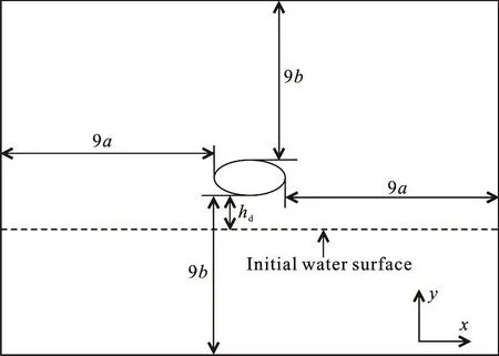
Fig. 3 Sketch of initial layout of the computational domain
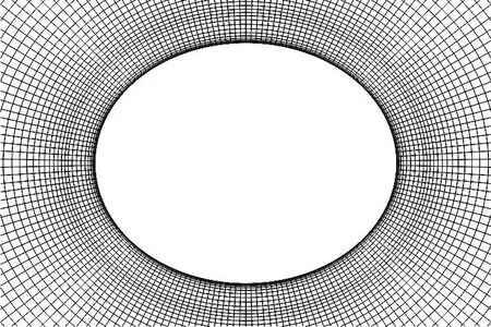
Fig. 4 Mesh layout around the ellipse (every 10th grid points is shown for clarity, b/ a=0.8)
2.4 Validation of the numerical method
First, the experiment of Lin and Shieh is chosen to validate the accuracy of the present numerical method in predicting the impact pressure distribution.In the experiment, a digital imaging system and a high speed data acquisition system were used to study the water entry of a cylinder. The cylinder used in the experiment with diameter of 0.203 m, thickness of 0.200 m and weight of 12.5 kg, four pressure gages with diameter of 5.5 mm were installed at radial angles θ=0°, 7.5°, 15° and 30° (numbered 1-4).Here the experimental case with the drop height of hd=0.050 m (corresponding to the impact velocity of V0=0.990 m/s) is chosen to validate the numerical accuracy of simulation.
In our simulation, the 2-D circular cylinder with unit length mass of 62.5 kg is used, the other parameters are the same as those in the experiment.The 2-D circular cylinder enters into water vertically in free fall motion. The effects of changing the mesh size and the Courant number are investigated as follows.
The reasonable normal mesh size for mesh independent solution is 7.0×10⁵. The coarse mesh and fine mesh sizes are 3.5×10⁵and 1.4×10⁶respectively. The comparison of the time histories of pressure coefficient for different mesh sizes is shown in Fig. 5. The results of normal mesh and fine mesh coincide well,which means the normal mesh is sufficient to obtain an accurate solution.
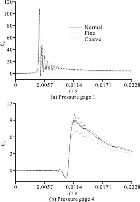
Fig. 5 The comparisons of the time histories of pressure coefficient for different mesh sizes
The Courant numbers of 0.25, 0.50, and 1.00 are used to investigate the effect of time step. The comparison of the time histories of pressure coefficient for different Courant numbers is shown in Fig. 6. The results for the Courant number of 0.25 and 0.50 are in excellent agreement. Therefore the Courant number of 0.25 is chosen.
The comparison of the time histories of pressure coefficient between the experiment and the simulation is shown in Fig. 7. For the four pressure gages, the pressure tendency and the peak value are in good agreement with the experiments. For the pressure gage of 0°, the CFD shows the same oscillations with the experiment. For the pressure gages of 7.5° and 15°,the CFD shows some oscillations which are not present in the experiments. The difference maybe comes from the air trapping effect. In the present CFD simulation, a 2-D model is used, thus the trapped air on the bottom of the cylinder can be predicted, which results in the pressure oscillations for the gages of 0°,7.5° and 15°. In the experiment, the 3-D effect can reduce the air trapping effect, thus the trapped air only appears at the gage of 0°, but disappears at the gages of 7.5° and 15° that results in the smooth pressure for the gages of 7.5° and 15°.
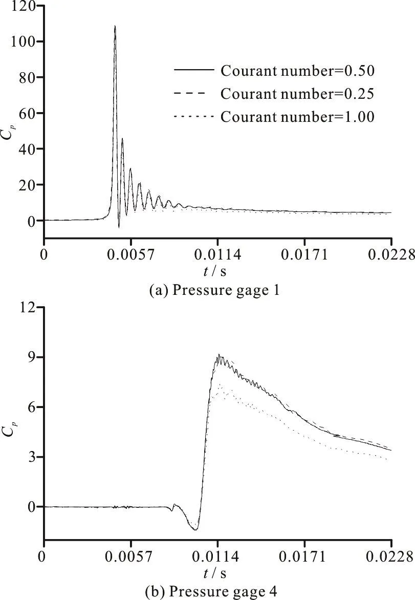
Fig. 6 The comparisons of the time histories of pressure coefficient for different Courant numbers
Second, the experiment of Cointe and Armand is chosen to validate the accuracy of the present numerical method in predicting the impact force during the cylinder water entry. Figure 8 shows the time history of the impact force coefficient from the experiment,the present simulation, and the potential-flow theories(such as von Kármán theory, the modified von Kármán theory, the Wagner theory, and the modified Wagner theory). One can see that the present computational result matches the experimental one very well. However, all the results of potential-flow theories disagree with the experimental one, except for the peek value of the impact force coefficient from the Wagner theory and the modified Wagner theory. Thus,it can be concluded that the present simulation can give a good prediction for the impact load history, but the potential-flow solutions based on the Wagner theory and the modified Wagner theory only can give satisfactory predictions for the peak of impact load.
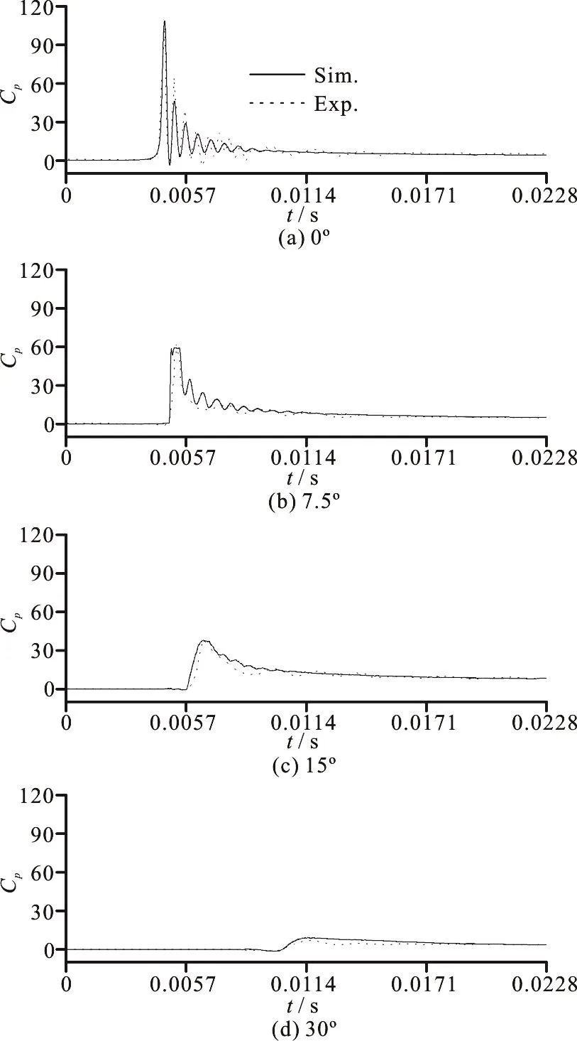
Fig. 7 Time histories of pressure coefficient from the experiment and the present simulation

Fig. 8 Time histories of the impact force coefficients from the experiment, present simulation, and potential-flow theories (von Kármán theory (von Kármán), the modified von Kármántheory(Faltinsen), Wagner theory (Wagner),and the modified Wagner theory (Fabula))
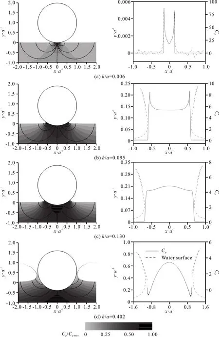
Fig. 9 Pressure coefficient contours and streamlines (left columns), pressure coefficient distribution and free water surface elevations (right columns) at different instants (b/ a=1.0, Fr=1.0)
Based on the above two validation cases, it can be said that the accuracy of the present CFD method is enough to study the effects of Froude number and geometry on the water impact performance of a 2-D ellipse.
3. Results and discussion
The vertical water entry processes of five different 2-D ellipse geometries (b/ a=0.5, 0.8, 1.0, 1.5 and 2.0) at five different constant speeds (V=0.495 m/s,0.792 m/s, 0.990 m/s, 1.980 m/s and 3.960 m/s,corresponding to Fr=0.5, 0.8, 1.0, 2.0 and 4.0) are simulated to study the effects of ellipse geometry and Froude number on ellipse water entry. The case without gravity with Fr=∞ is also calculated, for which V=3.960 m/s.
3.1 Typical water entry process
The typical water entry process of a 2-D circular cylinder at a constant speed V=0.990 m/s (corresponding to Fr=1.0) is illustrated to study the variations in the pressure and the flow field. Figure 9 shows the pressure coefficient contours, streamlines,pressure coefficient distribution on the ellipse and the free water surface elevation at different instants. The trapped air below the cylinder may cause an irregular oscillation of pressure on the bottom of the cylinder.To get a smooth result, the pressure is given by interpolation from outside oscillations region. When the cylinder just impacts the water at h/ a=0.006, as shown in Fig. 9(a), the water surface almost remains unchanged and the peak pressure coefficient located at the spray root is very large. When the cylinder enters deep into the water, the water surface rises up slightly and a little jet appears; the peak pressure coefficient location remains at the spray root. At h/ a=0.095, as shown in Fig. 9(b), the water surface rises up and the jet separates from the cylinder; the peak pressure coefficient appearing at the spray root is close to the pressure coefficient on the bottom. At h/ a=0.130,as shown in Fig. 9(c), the position of the peak pressure coefficient changes from the spray root to the bottom of the cylinder. At h/ a=0.402, as shown in Fig.9(d), the jet root separates from the cylinder, and the pressure at the jet root is almost equal to the standard atmospheric pressure.

Fig. 10 Time histories of pressure coefficients on the bottom and at spray root (b/ a=1.0, Fr=1.0)
Figure 10 shows the time histories of the pressure coefficients on the bottom of the cylinder and at spray root. It can be seen from Fig. 9 that the spray root disappears at a certain time, which causes the red curve representing pressure at spray root to interrupt.The averaged pressure at the bottom of the cylinder is used because the pressure oscillation appears at the bottom, as shown in Fig. 10. When the cylinder just enters into the water, the pressure coefficients at the spray root and on the bottom of the cylinder are all considerably large, and the former is greater than the later. As the time increases, the pressures of both spray root and bottom decrease, however the pressure at spray root deceases more sharply. At a critical time of hc/a=0.107, the pressure on the bottom is equal to that at the spray root. After the critical time, the pressure on the bottom is greater than that at the spray root. When the dimensionless time h/ a is larger than 0.300, the pressure on the bottom changes slightly.
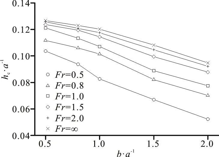
Fig. 11 Critical time corresponding to the peak pressure position shift for different ellipse geometries
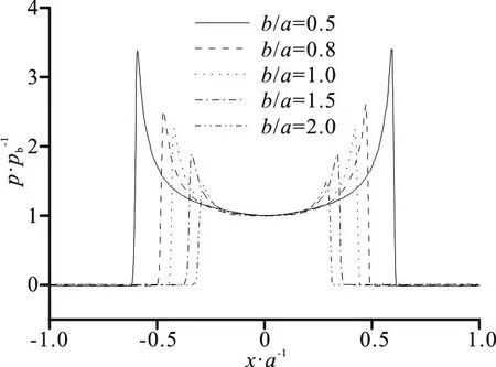
Fig. 12 Pressure distributions on different ellipse geometries (Fr=2.0, h/ a=0.050)
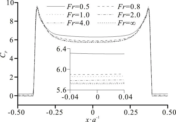
Fig. 13 Pressure coefficient distributions on the ellipse for different Froude numbers (b/ a=1.5, h/ a=0.060)
The critical time corresponding to the peak pressure position shift for different ellipse geometries are shown in Fig. 11. With increasing b/ a, the critical time decreases. As the Froude number increases, the critical time increases.

Fig. 14 Time histories of the coefficients of vertical force, buoyancy and impact force on the same ellipse geometry for different Froude numbers
In order to interpret the fact that the critical time changes with the ellipse geometry, the pressure distributions on different ellipse geometries at Fr=2.0,h/ a=0.050 are shown in Fig. 12, where pbis the pressure on the ellipse bottom and the relative pres-sure p/ pbrepresents the local pressure relative to that on the bottom. As b/ a increases the relative pressure at the spray root decreases. This is because the local deadrise angle increases with increasing b/ a. As shown in Fig. 10, the pressure on the ellipse bottom and the pressure at the spray root both decrease with the increase of time, and the pressure at the spray root relative to the pressure on the ellipse bottom is smaller for a greater b/ a at each time instant before the critical time, which can be deduced from Fig. 12. Then we can infer that as the time increases, for a greater b/ a, the pressure at spray root will be equal to that on the bottom earlier, and therefore the critical time is smaller.
In order to interpret the fact that the critical time changes with the Froude number, the pressure coefficient distributions on the ellipse of b/ a=1.5 at h/ a=0.060 for different Froude numbers are shown in Fig. 13. The pressure coefficients at the spray root are almost the same, which indicates that the effect of Froude number on the pressure coefficient at the spray root is negligible. As the Froude number increases, the gravity effect becomes weaker, resulting in that the pressure coefficient on the bottom decreases. Namely,for a greater Froude number, the pressure coefficient at the spray root relative to that on the bottom is greater. Then combining with that shown in Fig. 10,we can infer that the increase of Froude number leads to the increment in the critical time.
3.2 Vertical force
Figure 14 shows the time histories of the coefficients of vertical force, buoyancy and impact force on the same ellipse geometry for different Froude number.As the time increases, the impact force first increases to the peak in a short time and then gradually decreases to zero, and the buoyancy increases monotonically. Thus the vertical force first rapidly increases to the peak and then gradually decreases to the minimum(the bigger the Froude number, the latter is the time corresponding to the minimum), and finally increases gradually.
As the Froude number increases, before a certain time, the vertical force changes slightly which means that the effect of Froude number on the vertical force can be negligible, after that time, the vertical force decreases a lot which means that the effect of Froude number becomes more important. Therefore the water entry process can be divided into two stages. In the initial stage (h/ a<0.100), the impact force is much larger than the buoyancy, thus the vertical force is mainly from the impact force; the impact effect between the ellipse and the water surface governs the flow physics, thus it is called the impact dominated stage. In thelatestage (h/ a>0.100),thebuoyancy force is close to and even exceeds the impact force,thus the vertical force is determined by the buoyancy and impact force, the gravity effect and impact effect govern the flow physics together, thus it is called the impact and gravity dominated stage.
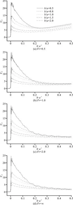
Fig. 15 Time histories of vertical force coefficients on different ellipse geometries at the same Froude number
Figure 15 shows the time histories of vertical force coefficients on different ellipse geometries at the same Froude number. Shortly after the ellipse touches the water surface, the vertical force sharply increases to its peak value. As the b/ a increases, the peak value decreases rapidly. The vertical forces tend to convergence over time. This means that the ellipse geometry has a strong effect on the vertical force in the initial stage, and has a very weak influence on the vertical force in the late stage.
3.2.1 Initial stage of water entry
Figure 16 shows the maximum value of vertical force coefficient in the initial stage of water entry. It can be concluded that the maximum vertical force depends heavily on the ellipse geometry, and is completely independent on the Froude number.
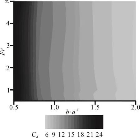
Fig. 16 Maximum value of verticalforce coefficientinthe initial stage of water entry
The classical Wagner theory was used to solve the maximum vertical force of cylinder water entry. In order to apply the Wagner theory to an ellipse water entry, the corresponding formula should be derived as follows.
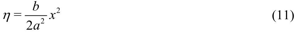
For ellipse water entry, η(x) is determined by

Because η is small in the initial stage, therefore the high order can be ignored. Then we can find
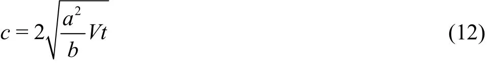
According to Faltinsen[18], one can get the half of wetted width of ellipse
When the ellipse touches the water surface, the maximum vertical force is
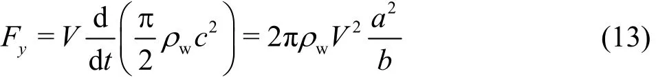
Thus,
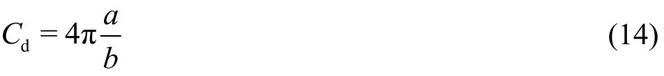
Table 1 shows the relative differences in the maximum vertical force coefficients obtained from the CFD simulation compared to that obtained from the analytical theory of Wagner. It can be seen that the relative difference is between -7.8% and 5.7%, which means that the results from the Wagner theory match the CFD simulation results quite well for the peak value.2.0, h/ a=0.050. As the b/ a decreases, the water surface deforms more severely, the pressure coefficients at the spray root and on the bottom increase,and the wetted width increases, resulting in the increase of vertical force as illustrated in Fig. 14.
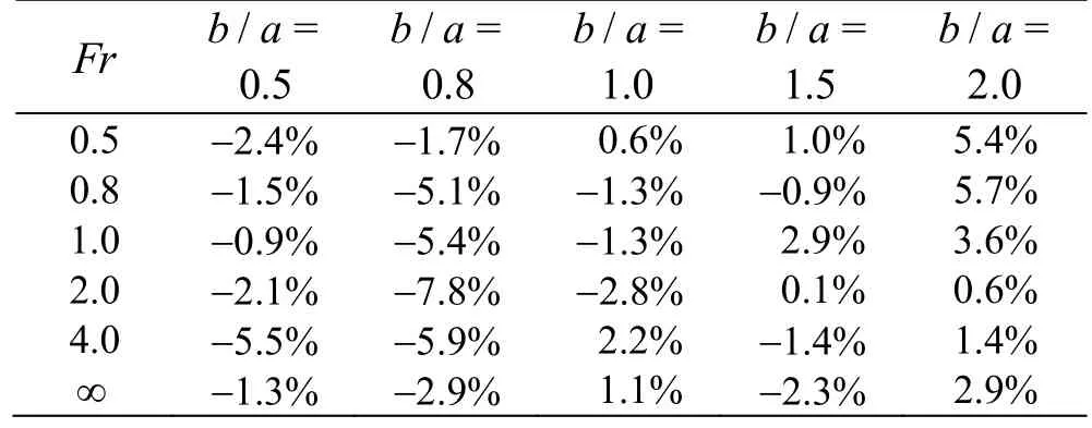
Table 1 Relative differences in the maximum vertical force coefficients obtained from the CFD simulation compared to that obtained from Wagner theory
From Fig. 8, Table 1, it can be said that the Wagner theory ignoring the viscosity, turbulence,surface tension, gravity, and compressibility can be used to predict the peak value of the vertical force in the initial stage of water enry, but can not predict the time history of the vertical force. The present CFD method takes into account the above factors, thus the separation of jet and the splashing can be predicted (as shown in Figs. 9, 17(a)), sequently the time histories of the free-surface deformation, pressure distribution and impact load can be predicted accurately.
Figure 17 shows the water surface elevation and pressure coefficient distribution on ellipse for Fr=
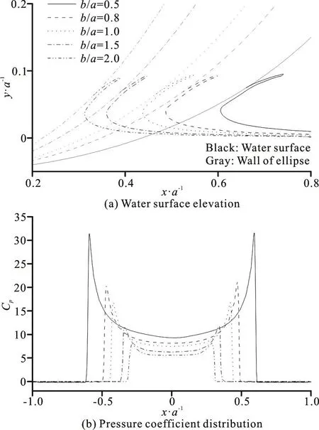
Fig. 17 Water surface elevation and pressure coefficient distribution on ellipse (Fr=2.0,h/ a=0.050)
3.2.2 Late stage of water entry
In order to study the effect of Froude number on the vertical force in the late stage of ellipse water entry, the pressure coefficient distributions on the ellipse of b/ a=0.8 is shown in Fig. 18, for different Froude numbers at h/ a=0.400. As the Froude number increases, the gravity effect gradually wears off, resulting in the decrease of the pressure on the bottom of ellipse and even decrease in vertical force as shown in Fig. 14.
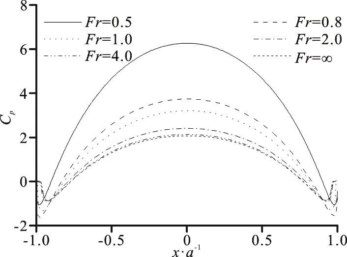
Fig. 18 Pressure coefficient distributions on ellipse for different Froude numbers (b/ a=0.8, h/ a=0.400).
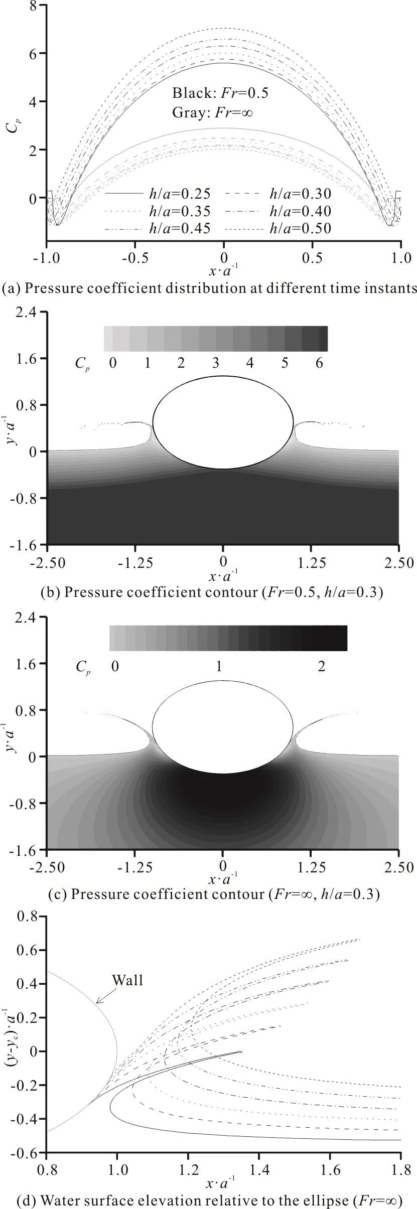
Fig. 19 Pressure coefficients and water surface elevations in the late stage of water entry of the ellipse with b/ a=0.8
Figure 19 shows the pressure coefficient and water surface elevation at different time instants in the late stage of water entry of the ellipse with b/ a=0.8.When the entry depth increases, the pressure on the bottom of ellipse increases for Fr=0.5 and slightly decreases for Fr=∞ (as shown in Fig. 19(a)), thus the vertical force increases for Fr=0.5 and slightly decreases for Fr=∞ (as shown in Figs. 15(a),15(d)). The reason why the variation of pressure coefficient on the bottom of ellipse with time changes with Froude number can be found in Figs. 19(b)-19(d).The pressure coefficient contours of water flow field around the ellipse at h/ a=0.300 are shown in Figs.19 (b), 19(c). For Fr = 0.5, there is an obvious pressure stratification along the depth direction, which means that the gravity plays an important role. For Fr=∞, there is no pressure stratification along depth direction, and the high pressure near the ellipse is completely from the impact effect. As the entry depth increases, the impact effect decreases and the gravity effect increases, thus the pressure at Fr=0.5 increases because the latter is stronger than the former and the pressure at Fr=∞ slightly decreases. Figure 19(d) shows the water surface elevation relative to ellipse at different time instants for Fr=∞. As the entry depth increases, the jet separation point changes slightly, which results in the slightly change in pressure coefficient distribution at the spray root as shown in Fig. 19(a).
4. Conclusion
The CFD simulations are conducted to study the effects of Froude number and geometry on a 2-D ellipse water entry. The vertical force, pressure distribution and water surface elevation are obtained. The CFD method can predict the time history of the vertical force more accurately than the classical potential-flow theories by considering the viscosity,turbulence, surface tension, gravity, and compressibility. The results show that the peak pressure position first appears at the spray root, and then changes to the bottom of the ellipse after a critical time. As the ratio b/ a or the Froude number increases, the critical time increases. The process of ellipse water entry can be divided into two stages. In the initial stage, the ellipse geometry plays an important role and the influence of Froude number can be negligible. A smaller b/ a can lead to a greater vertical force. While in the late stage, the Froude number has important impact, and the vertical force decreases with increasing Froude number. The classical Wagner theory is extended to the ellipse water entry, and the predicted maximum value of vertical force coefficient in the initial stage is 4πa/ b. The results can be used in applications such as the design of helicopter or airplane fuselage where the cross-sectional shape of the fuselage may be approximated by an ellipse.
猜你喜欢
红蜻蜓·高年级(2022年6期)2022-06-16
作文小学高年级(2021年9期)2021-12-25
作文成功之路·中考冲刺(2021年11期)2021-12-16
音乐天地(音乐创作版)(2020年2期)2020-04-18
青年歌声(2020年2期)2020-02-27
散文诗(2017年2期)2017-06-05
小天使·一年级语数英综合(2017年4期)2017-04-18
丹青少年(2017年2期)2017-02-26
创业家(2015年1期)2015-02-27

- 水动力学研究与进展 B辑的其它文章
- Call For Papers The 3rd International Symposium of Cavitation and Multiphase Flow(ISCM 2019)
- Investigation of the hydrodynamic performance of crablike robot swimming leg *
- Determination of epsilon for Omega vortex identification method *
- Transient curvilinear-coordinate based fully nonlinear model for wave propagation and interactions with curved boundaries *
- Tracer advection in a pair of adjacent side-wall cavities, and in a rectangular channel containing two groynes in series *
- Numerical simulation of transient turbulent cavitating flows with special emphasis on shock wave dynamics considering the water/vapor compressibility *