油气悬架囊式蓄能器真实气体多变指数模型建立及验证
2019-12-19 01:12王云超杨岳霖
农业工程学报 2019年20期
王云超,魏 彬,杨岳霖
油气悬架囊式蓄能器真实气体多变指数模型建立及验证
王云超,魏 彬,杨岳霖
(集美大学机械与能源工程学院,厦门 361021)
蓄能器内氮气多变过程模型的精度是影响油气悬架系统特性分析的关键因素之一。为了更加精准地描述蓄能器内氮气的真实多变过程,该文利用蓄能器试验台开展了蓄能器不同振幅和频率的正弦激励试验,通过试验数据综合分析发现氮气体积压缩率和体积压缩速率与气体压力呈一定线性关系。在此基础提出了一种基于体积压缩率和体积压缩速率的真实气体多变指数模型。为了验证模型的正确性和准确性,通过蓄能器试验数据对提出的多变指数模型中的2个变量系数进行辨识和模型仿真结果的对比验证,并利用6个悬挂缸的整车油气悬架系统试验平台对模型进行试验验证,结果表明:仿真预测结果与试验数据的平均误差为5.12%,最大误差小于10.9%,满足工程设计的要求。该囊式蓄能器的气体多变指数模型为更加准确研究油气悬架系统真实特性奠定了基础。
车辆;试验;模型;悬架;蓄能器;迟滞环
0 引 言
油气悬架系统以其高度的非线性特性及高能量密度等优点[1],被广泛应用于越野车领域。油气悬架系统的研究也经历了从单个悬架系统的特性研究[1-6]到不同连通方式的整车油气悬架系统特性仿真分析和研究[7-15]。已有研究大部分都是基于理想气体的多变过程建立的油气悬架系统模型[2-15],而实际油气悬架系统内的氮气的多变过程并非理想的多变过程[1]。Kat等[16]曾强调只有经过正确参数验证的模型获得的结果才有意义。为此,很多学者针对实际气体的多变过程进行了深入的研究[17-30],主要集中在2个方面:1)从热传递和能量守恒角度研究气体多变过程模型[17-26];2)从理论和试验角度研究确定气体多变指数的问题[27-30]。
根据能量守恒定律,在BWR(Benedict-Webb-Rubin)真实气体模型的基础上[17],Otis等[18]建立了一个热对流模型来描述气体热动力学过程,并建立了一个热时间常数模型。Els等[19]在此基础上,分析了油气悬架系统对时间和温度的依赖性。Pourmovahed等[20]提出了一种基于试验数据的热时间常数关联模型,并准确预测蓄能器的热力学损失和压缩或膨胀过程中的气体压力和温度历史。Els等[21]进一步建立了一个气体与油液、环境的热传递模型,并发现油气悬架系统内存在显著的固有阻尼,这主要根源于热传递不是单纯的温度变化或能量积累。吴宏涛等[22]通过热平衡试验研究了激励振幅、激励频率和温度变化等对油气悬架动态特性的影响规律。Westhuizen等[1]对比分析了3种理想气体模型和2种实际气体模型的实用性,认为应该根据实际需要选择合适的模型。陈轶杰等[23]建立了油气悬架的自然对流热力学模型。黄夏旭等[24]利用热学理论、气体状态方程,建立包含缸筒、活塞杆热容的非公路自卸车油气悬架系统的集中参数热力学模型。但是研究发现针对具体的蓄能器及其工作范围,热时间常数必须通过试验测量获得。最近,Victor等[25]的研究发现:当压缩比变化时,对于采用恒定热时间常数的模型,预测精度会降低。范基等[26]经过试验研究阐释了热时间常数并不是一个常数,即使同一个蓄能器,也会随工况和蓄能器容量的变化而不同。总之,热时间常数确定问题是以上研究的主要困难,另外,模型验证方面还缺乏高频振动的试验验证,而且以上研究主要针对活塞式蓄能器(piston-type hydraulic accumulator)。
其他部分学者试图通过理论推导和试验方法确定气体多变过程指数的实际取值,从而描述真实气体的多变过程。封士彩等[27-28]通过试验研究认为实际状态的气体多变指数值要比理论值大,其取值与激励频率有关。王德伟[29]认为气体压缩速率对气体多变指数影响较大,并构造一个气体压缩率的气体多变指数模型,试图找出蓄能器在充压过程中气体多变指数具体数值的确定方法,但是,其模型的正确性缺乏试验验证。吴晓元等[30]从理论角度对气囊式蓄能器气体多变指数的数值域问题进行了推导和分析,认为气囊式蓄能器气体多变指数的值域范围为1~1.4。但是,这些都是基于理想气体多变过程获得的结果,与实际还存在一定的误差。总之,以上研究依然无法描述蓄能器内真实气体的压力和体积关系图中迟滞环的现象。
综上所述,为了描述气体多变过程指数描述蓄能器的迟滞现象和简化蓄能器内气体的建模,本文通过对蓄能器多个工况的试验数据综合分析,发现影响蓄能器特性的2个关键因素,并提出一种真实气体多变指数模型,并进行了仿真和试验分析和验证。
1 蓄能器的氮气正弦激励试验和分析
1.1 试验仪器及原理
试验原理:利用伺服激励油缸控制一个被动液压缸按照正弦规律运动,其无杆腔的油口与蓄能器进油口连接,蓄能器的充气口接有一个压力传感器,用来测量蓄能器内气体的压力变化,如图1a。测试系统主要参数如表1所示。
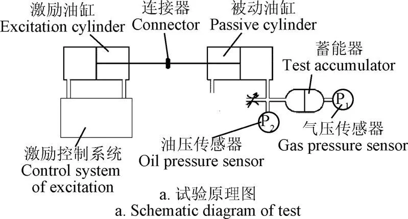
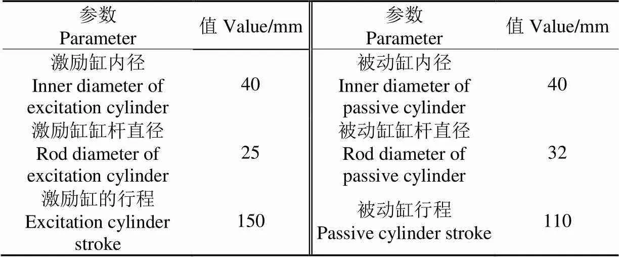
表1 试验台主要参数
主要仪器设备:1)MEACON的MIK-P300系列压力传感器;2)Novotechnik的TP1系列位移传感器;3)上海元隆工业自动化电器有限公司(YOLON)HOB系列油缸;4)北京机床所精密机电有限公司QDY-Ⅱ系列电液伺服阀,型号:QDY6;5)SVA系列伺服放大器,型号:SVA-Ⅱ(TY)型;6)被动油缸为自制油缸。
根据试验台的工作范围,确定如下试验内容:1)振幅20 mm,频率为0.1~0.4 Hz的4种正弦激励试验;2)频率为0.4 Hz,振幅为5~20 mm的4种正弦激励试验。
试验方法:通过控制正弦激励的振幅和频率,分析激振幅值和频率对气体压力的影响,从而分析气体压力的主要影响因素。
1.2 试验结果及分析
经过蓄能器氮气试验数据综合分析发现2个影响气体压力的主要因素,为了便于对试验结果进行分析,首先对其进行定义:
体积压缩率:
=−Δ/0(1)
体积压缩速率:
=Δ/0(2)
式中0蓄能器的体积,L;Δ为蓄能器内的氮气体积变化量(L),Δ,,分别为被动油缸的无杆腔面积(100 cm2)和位移量(10 cm),等于激励油缸的位移(被动油缸被压缩为正,即气囊被压缩时,位移为正);Δ为Δ的变化率,Δ;为被压缩油缸的运动速度(10 cm/s)。试验结果如图2所示。

图2 正弦激励下气体压力与体积压缩率的关系
由图2a可知,对应于体积压缩率最小和最大值的各频率下的气体压力曲线分别交于(−0.06,3.07)和(0.06,4.99),说明激振频率对气体压力变化斜率(刚度)没有明显影响。但是随着振动频率的提高,蓄能器内气体的迟滞环越来越大,说明蓄能器内的气体内阻尼不断增大。主要是由于真实气体内部分子间的相互作用加剧导致阻尼力增大以及散热时间减少所致,另外,油液从被动油缸无杆腔到蓄能器的管路和接口也会有部分阻尼的影响,但管路阻尼专项试验结果表明该阻尼影响小于0.015 MPa。由于试验条件限制,尚缺乏较高频率振动试验数据,而相同振幅下较高频振动时的体积压缩率极值对应的气体压力点是否仍然汇交于一点仍需进一步的试验验证。
由图2b可知,随着正弦激励的振幅从5 mm增大到20 mm,各振幅压力曲线的最小和最大体积压缩率对应的气体压力基本位于(−0.065,3.074)和(0.065,4.105)两点的连线上,即气体压力与体积压缩率成线性关系。同样由于试验条件限制,未进一步探讨更大振幅、更高频率激励作用的试验研究,因此,体积压缩率的极值点对应的气体压力点是否依然存在线性关系仍需进一步验证。
2 真实气体多变指数模型
2.1 体积压缩率和体积压缩速率对多变指数的影响
蓄能器内的氮气多变过程是不可逆的,因此,气体多变指数在该过程中按照一定方式进行变化[1]。
理想气体多变过程方程
00=PV (3)
式中0为蓄能器充气压力,Pa;为蓄能器气体瞬时体积,mm3;为蓄能器气体瞬时压力,为气体多变指数,其值由气体比热容、比定压热容及比定容热容决定。
由式(3)可得气体多变指数为
=lg(0/)/lg(/0) (4)
将图2中的试验数据代入式(4),得到真实气体多变指数,利用Matlab绘制气体多变指数随体积压缩率的变化规律,如图3所示。
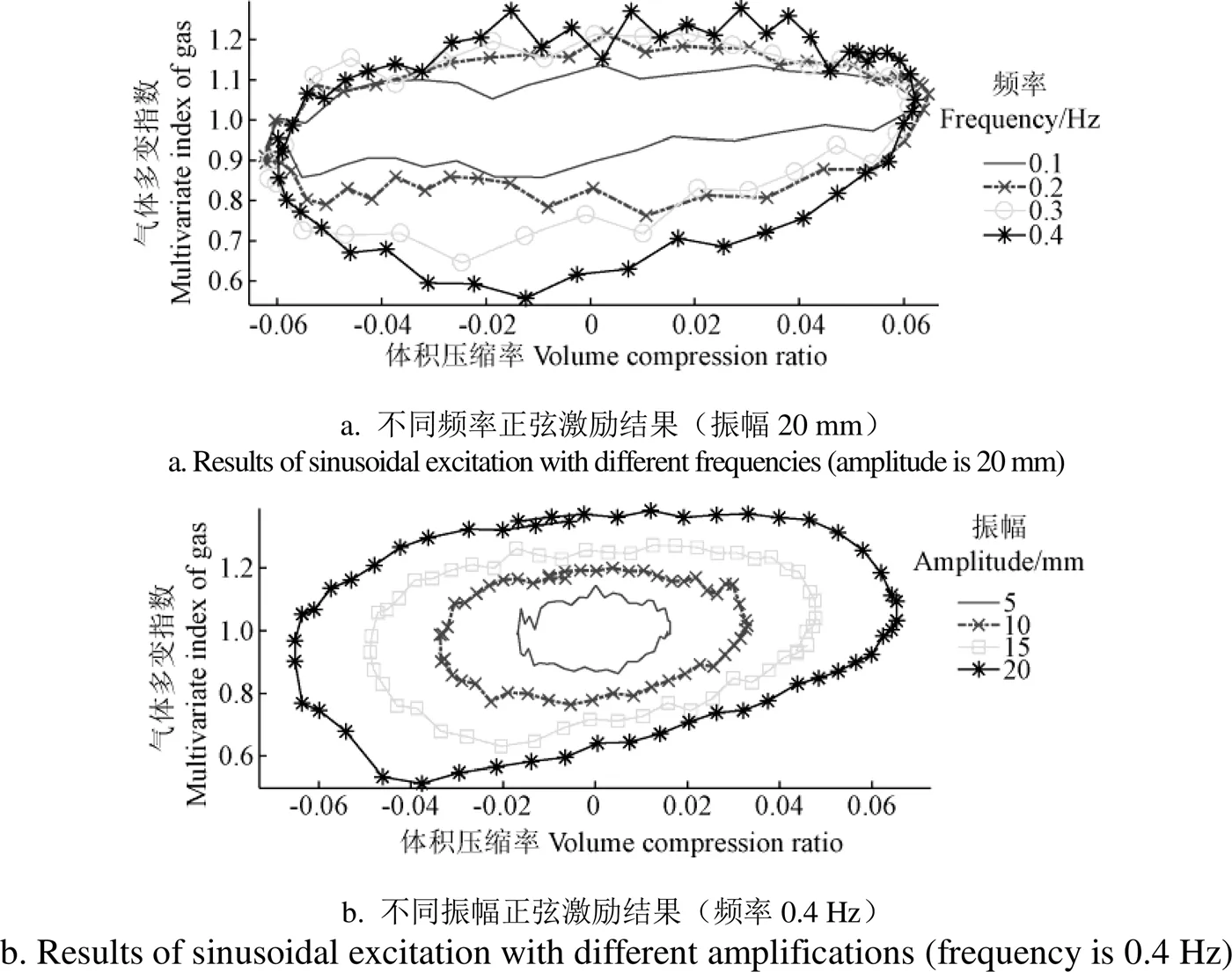
图3 正弦激励下气体多变指数与体积压缩率的关系
从图3a不同频率的气体多变指数变化可以看出,不同频率的振动,其极限体积的气体多变指数也基本交于一点。另外,频率对压缩过程的影响不大,而对膨胀过程的影响比较明显,其主要是由激振速度信号引起的,试验的激励位移信号近似正弦,但激振油缸信号在膨胀过程的实际速度明显大于压缩行程。这也反映了压缩速度对气体压力和多变指数的影响,具体详见图4a,从图中可以看出气体多变指数与压缩速率表现为一定的线性比例。
从图3b可以看出,随着振幅增大,气体多变指数也不断增大,并且气体多变指数的变化范围也不断增大。另外,还发现不同振幅的气体多变指数的极值点近似一条直线上,说明在一定频率下,气体压缩率与气体多变指数呈一定线性关系。这也反映了激振速度对气体多变指数的影响,具体详见图4b,从图中也可以看出气体多变指数与压缩速率成一定线性比例。
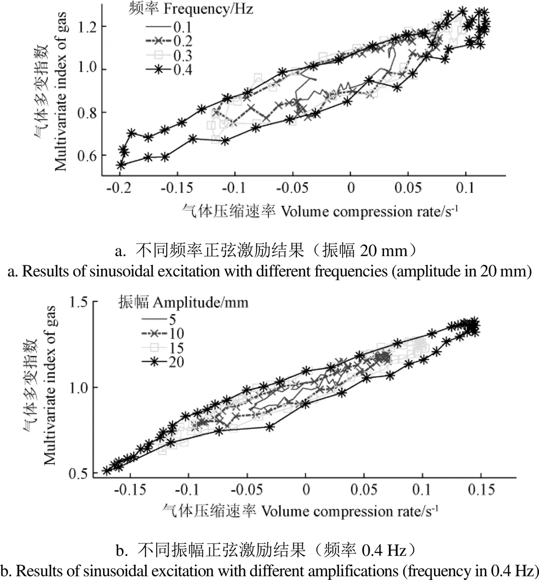
图4 正弦激励下气体多变指数与体积缩速率的关系
2.2 真实气体多变指数模型
假设不考虑气体压缩率和气体压缩速率的影响时,蓄能器内气体的变化为等温过程,即气体多变指数为1。因此,真实气体的多变过程指数可以表示为
=1+1+2(5)
式中1为气体多变指数体积压缩率系数,其值由图3b中体积压缩率的最小和最大值对应的气体多变指数连线的斜率决定,即可通过试验数据辨识获得。1理论上可以根据真实气体的BWR模型,由2个极限位置的气体温度和质量体积数值以及公式(5)和理想气体的多变过程状态方程计算获得。但是其涉及到气体温度的预测中热时间常数的确定问题。因此,导致其回归为传统方法,失去本方法的意义。如果环境温度不随气体温度变化,1为0。如果将蓄能器内的氮气视为一个振动系统,1可等效为系统的刚度系数;为弹性变形量;2为气体多变指数体积压缩速率系数,其数值由图4a中体积压缩速率的最小和最大值对应的气体多变指数连线的斜率决定,反映了压缩速率引起的气体内能(热交换和做功综合作用结果)、气体内阻尼等的综合影响,2可等效为振动系统的阻尼系数;为速度,mm/s。
2.3 真实气体多变指数模型的验证
为了验证真实气体多变指数模型的正确性和精度,利用蓄能器的试验数据对式(5)中的2个系数1和2进行辨识,可得1=2.4,2=1.5,将这2个系数代入式(5)可获得多变指数,再将代入多变过程状态方程,可得
=0(0/)1+2.4η+1.5ε(6)
将蓄能器各个工况测得的、和代入公式(6),利用Matlab软件,对各种工况的仿真结果与试验数据进行对比,结果如图5所示。
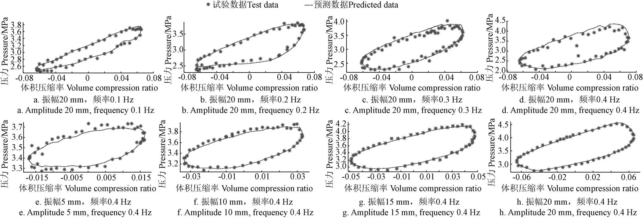
图5 正弦激励下气体模型预测压力与试验数据对比(蓄能器充气压力2 MPa,充油压力3.5 MPa)
由图5可知,正弦激励下气体模型预测压力与试验结果的整体平均误差为4.05%。图5 d图的误差最大,为10%,该误差是测量值出现了明显波动造成的,相同工况的测试结果(图5h)的最大误差只有2.25%。
为了进一步验证模型,多变指数模型中的1和2保持不变,将蓄能器的充气压力降为1.5 MPa,充油后平衡位置的压力为3.5 MPa,振幅0.02 m,不同频率的仿真和测试结果对比如图6所示,由图可知,正弦激励下气体模型预测压力与试验结果的最大误差为9.06%,整体平均偏差为2.01%。
从不同频率、振幅的仿真模型预测和测试数据的对比结果看,真实气体多变指数模型能够很好的跟踪真实气体的多变过程。即便是改变了蓄能器的充气压力,其仍然能够很好地预测试验结果。
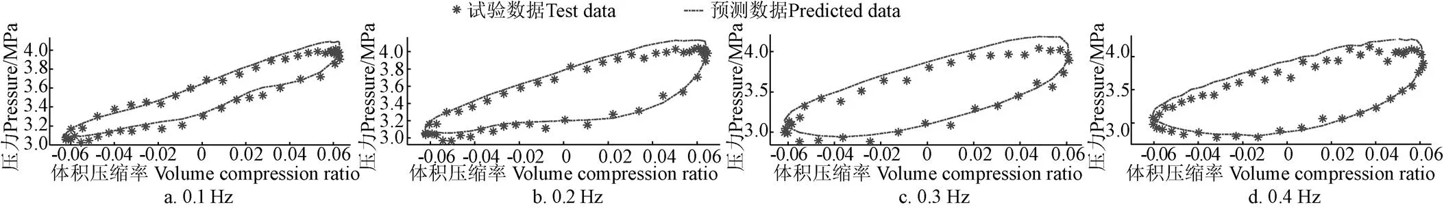
图6 正弦激励下气体模型预测压力与试验数据对比(振幅20 mm,蓄能器充气压力1.5 MPa,充油压力3.5 MPa)
3 整车油气悬架系统性能验证试验
3.1 试验仪器设备
为了进一步分析验证真实气体多变指数模型的适用性,多变指数模型中的1和2仍然保持不变,利用自主开发的整车悬架系统综合性能测试平台(图7)进行了侧倾工况试验,试验参数及设置如表2所示。
根据试验台的工作范围,确定以下试验内容:1)振幅20 mm,频率为0.1~0.4 Hz的4种正弦激励试验;2)频率为0.4 Hz,振幅为5~20 mm的4种正弦激励试验。
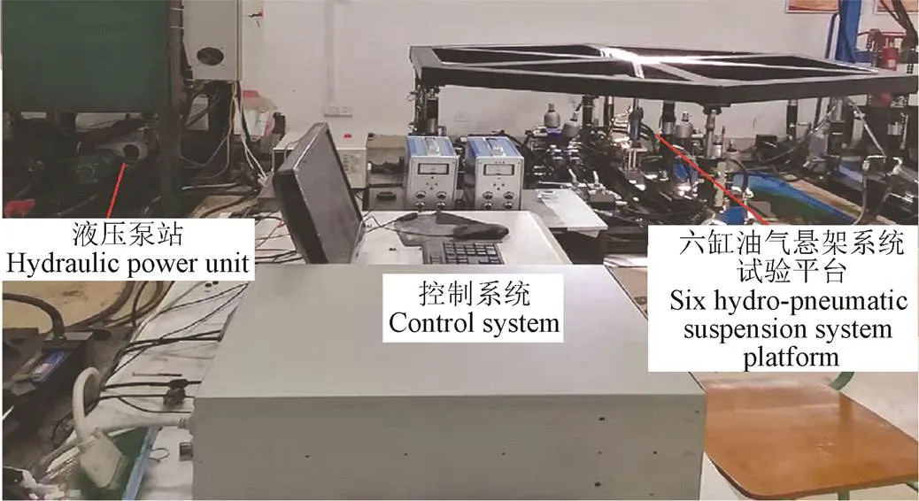
图7 整车油气悬架系统测试平台
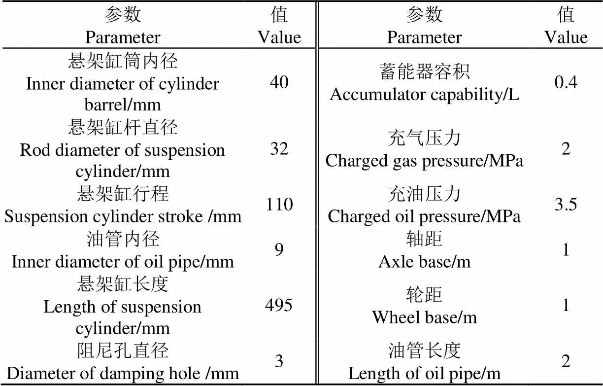
表2 测试平台主要参数
试验方法:通过控制正弦激励的振幅和频率,获得不同激振幅值和频率下的悬架系统的侧倾力矩,验证基于气体多变指数模型的6缸油气悬架系统联合仿真模型的预测精度。
3.2 测试和仿真对比验证
整车油气悬架系统的侧倾力矩测试和仿真对比结果如图8和图9所示。由图可以看出,油气悬架系统刚度(各曲线的极值点(2个顶点)连线的斜率)的预测值和测试结果具有很好的一致性。而油气悬架系统的阻尼力(曲线的迟滞环的大小)预测结果和测试结果存在一定的偏差,最大误差为10.9%,总体平均误差为5.12%。因此,本文提出的真实气体多变指数模型在一定范围内具有较高的预测精度。
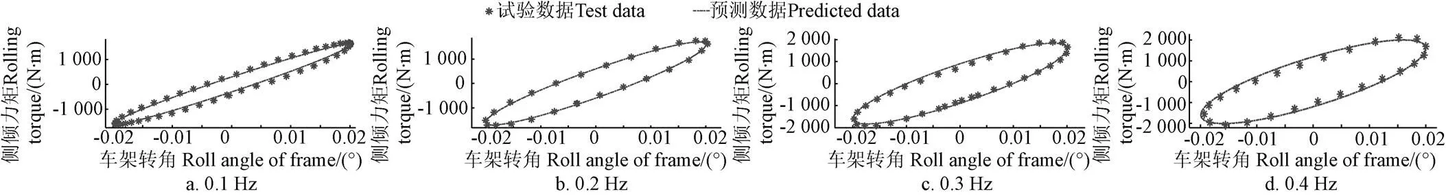
图8 振幅20 mm下不同频率正弦激励的侧倾力矩预测与试验数据对比
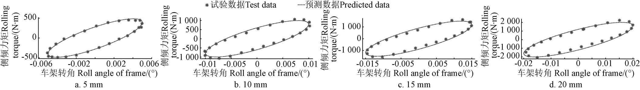
图9 不同振幅正弦激励的侧倾力矩预测值与试验数据对比(频率0.4 Hz)
4 结 论
本文分析了油气悬架系统蓄能器氮气建模现状及存在的问题,针对存在的问题开展研究,并取得以下成果:
1)通过蓄能器的试验研究发现:真实的氮气多变过程的2个主要影响因素为体积压缩率和体积压缩速率。
2)针对2个主要影响因素提出了一种新的气体多变指数模型,该模型具有参数少、模型简单、便于试验辨识等优点。在研究范围内,该模型的整体平均误差小于4.05%,最大误差为9.06%。
3)不同振幅和频率的蓄能器和整车油气悬架系统的试验验证表明:基于提出的真实气体多变指数模型的油气悬架系统仿真模型的预测结果和试验数据的整体平均误差为5.12%,最大误差为10.9%,具有较高精度。
[1] S Francois van der Westhuizen, P Schalk Els. Comparison of different gas models to calculate the spring force of a hydropneumatic suspension[J]. Journal of Terramechanics, 2015, 57: 41-59.
[2] 李仲兴,郭子权,王传建,等. 越野车用两级压力式油气弹簧的建模与仿真[J]. 振动. 测试与诊断,2017,37(3):512-517,629.
Li Zhongxing, Guo Zhiquan, Wang Chuanjian, et al. Modeling and simulating of a two-stage pressure hydro-pnenumatic spring for off-road vehicle[J]. Journal of Vibration, Measurement & Diagnosis, 2017, 37(3): 512-517, 629. (in Chinese with English abstract)
[3] 乐文超,时岩,彭安琪,等. 基于主动油气悬架的某重型车平顺性研究[J]. 振动与冲击,2016,35(24):183-188.
Yue Wenchao, Shi Yan, Peng Anqi, et al. Study on ride comfort of a heavy vehicle based on active hydro-pneumatic suspension[J]. Journal of Vibration and Shock, 2016, 35(24): 183-188. (in Chinese with English abstract)
[4] 陈雨,陈随英,杜岳峰,等. 基于摩擦阻尼的高地隙农机底盘悬架减振特性[J]. 农业工程学报,2016,32(7):51-57.
Chen Yu, Chen Suiying, Du Yuefeng, et al. Damping characteristics of chassis suspension system of high clearance agricultural machinery based on friction damper[J]. Transactions of the Chinese Society of Agricultural Engineering (Transactions of the CSAE), 2016, 32(7): 51-57. (in Chinese with English abstract)
[5] Nieto A J, Morales A L, Gonza lez A, et al. An analytical model of pneumatic suspensions based on an experimental characterization[J].Journal of Sound and Vibration, 2008, 313: 290-307.
[6] Yin Y, Rakheja S, Yang J, et al. Characterization of a hydro-pneumatic suspension strut with gas-oil emulsion[J]. Mechanical Systems and Signal Processing, 2018, 106: 319-333.
[7] 田文朋,易小刚,郭磊,等. 七桥混合耦连油气悬架车辆仿真与试验[J]. 中国机械工程,2018,29(9):1084-1089.
Tian Wenpeng, Yi Xiaogang, Guo Lei, et al. Simulation and experiments for seven spindled hybrid coupled hydro pneumatic suspension vehicles[J]. China Mechanical Engineering, 2018, 29(9): 1084-1089. (in Chinese with English abstract)
[8] 田文朋,杨宜坤,王伟. 油气悬架耦连形式对车辆稳定性的影响[J]. 汽车工程,2017,39(12):1362-1367,1389.
Tian Wenpeng, Yang Yikun, Wang Wei. The influence of the interconnection forms of hydro-pneumatic suspension on vehicle stability[J]. Automotive Engineering, 2017, 39(12): 1362-1367, 1389. (in Chinese with English abstract)
[9] 孙会来,金纯,张文明,等. 考虑驱动电机激振的电动车油气悬架系统振动分析[J]. 农业工程学报,2014,30(12):51-57.
Sun Huilai, Jin Chun, Zhang Wenming, et al. Vibration analysis of hydro-pneumatic suspension system based on drive motor excitation force[J]. Transactions of the Chinese Society of Agricultural Engineering (Transactions of the CSAE), 2014, 30(12): 51-57. (in Chinese with English abstract)
[10] Yin Yuming, Rakheja Subhash, Boileau Paul-Emile. Multi- performance analyses and design optimisation of hydro-pneumatic suspension system for an articulated frame-steered vehicle[J]. Vehicle System Dynamics, 2019, 57(1): 108-133.
[11] Cao D, Rakheja S, Su C Y. Roll-and pitch-plane coupled hydro-pneumatic suspension: Part 1: feasibility analysis and suspension properties[J]. Vehicle System Dynamics, 2010, 48(3): 361-386.
[12] Zhu Hengjia, Yang James, Yunqing Zhang. Modeling and optimization for pneumatically pitch-interconnected suspensions of a vehicle[J]. Journal of Sound and Vibration, 2018, 432: 290-309.
[13] Smith W A, Zhang N, Jeyakumaran J. Hydraulically interconnected vehicle suspension: theoretical and experimental ride analysis[J]. Vehicle System Dynamics, 2010, 48(1): 41-64.
[14] Kyuhyun Sim, Hwayoung Lee, Ji Won Yoon, et al. Effectiveness evaluation of hydro-pneumatic and semi-active cab suspension for the improvement of ride comfort of agricultural tractors[J]. Journal of Terramechanics, 2017, 69: 23-32.
[15] Zheng Enlai, Zhong Xinyu, Zhu Rui, et al. Investigation into the vibration characteristics of agricultural wheeled tractor- implement system with hydro-pneumatic suspension on the front axle[J]. Biosystems Engineering, 2019, 186: 14-33.
[16] Kat C J, Els P S. Validation metric based on relative error[J]. Mathematical and computer modelling of dynamical systems: methods, tools and application in engineering and related sciences, 2012, 18(5): 487-520.
[17] Cooper H W, Goldfranck J C. B-W-R constants and new correlations[J]. Hydrocarbon Processing, 1967, 46(12): 141-146.
[18] Otis D R, Pourmovahed A. An algorithm for computing nonflow gas processes in gas springs and hydro- pneumatic accumulators[J]. Journal of Dynamic Systems, Measurement, and Control, 1985, 107: 93-96.
[19] Els P S, Grobbelaar B. Investigation of the time- and temperature dependency of hydro-pneumatic suspension systems[J]. SAE Technical Paper Series, 1993, 3: 55-62.
[20] Pourmovahed A, Otis DR. An experimental thermal time constant correlation for hydraulic accumulators[J]. Transactions of the ASME, Journal of Dynamic Systems, Measurement and Control, 1990, 112: 116-121.
[21] Els P S, Grobbelaar B. Heat transfer effects on hydropneumatic suspension systems[J]. Journal of Terramechanics, 1999, 36: 197-205.
[22] 吴宏涛,张明. 油气弹簧热平衡仿真及试验研究[J]. 车辆与动力技术,2007,107(3):37-40.
Wu Hongtao, Zhang Ming. Hydro-pneumatic spring thermal equilibrium simulation and test research[J]. Vehicle and Power Technology, 2007, 107(3): 37-40. (in Chinese with English abstract)
[23] 陈轶杰,赵博,张旭,等. 基于随机激励的油气悬挂温升现象研究[J]. 机械强度,2010,32(6):869-872.
Chen Yijie, Zhao Bo, Zhang Xu, et al. Research on the temperature rise of hydro-pneumatic suspension under the random power[J]. Journal of Mechanical Strength, 2010, 32(6): 869-872. (in Chinese with English abstract)
[24] 黄夏旭,申焱华,杨珏,等. 基于集中参数热模型法的自卸车油气悬架系统热分析[J]. 农业工程学报,2013,29(10):64-70.
Huang Xiaxu, Shen Yanhua, Yang Jue, et al. Thermal analysis of hydro-pneumatic suspension system for dumper based on a lumped-parameter thermal model[J]. Transactions of the Chinese Society of Agricultural Engineering (Transactions of the CSAE), 2013, 29(10): 64-70. (in Chinese with English abstract)
[25] Victor Irizar, Casper Schousboe Andreasen. Hydraulic pitch control system for wind turbines: Advanced modeling and verification of an hydraulic accumulator[J]. Simulation Modelling Practice and Theory, 2017, 79: 1-22.
[26] 范基,吴劲. 蓄能器的蓄能性能研究[J]. 液压工业,1990(2):2-6.
[27] 封士彩. 气囊式蓄能器气体多变指数理论值和实际值的确定[J]. 液压与气动,2002(5):3-5.
Feng Shicai. Determining the air polytropic exponent value both theoretical and practical for bladder accumulator[J]. Chinese Hydraulics & Pneumatics, 2002(5): 3-5. (in Chinese with English abstract)
[28] 封士彩,徐勇,鹿洪禹. 工程车辆油气悬架蓄能器性能的试验研究[J]. 工程机械,2001(9):8-11,1.
Feng Shicai, Xu Yong, Lu Hongyu. Test and study for the performance of oil-gas suspension accumulators on engineering vehicles[J]. Construction Machinery and Equipment, 2001(9): 8-11,1. (in Chinese with English abstract)
[29] 王德伟. 蓄能器充压过程中气体多变指数的确定[J]. 液压与气动,2007(9):78-79.
Wang Dewei. Determination of the gas polytropic exponent in the charge process of the energy accumulator[J]. Chinese Hydraulics & Pneumatics, 2007(9): 78-79. (in Chinese with English abstract)
[30] 吴晓元,陈忠基,王世东,等. 气囊式蓄能器气体多变指数值域的研究[J]. 鞍山科技大学学报,2003(3):204-220.
Wu Xiaoyuan, Chen Zhongji, Wang Shidong, et al. Study of range of air polytropic exponent value for bladder accumulator[J]. Journal of University of Science and Technology Liaoning, 2003(3): 204-220. (in Chinese with English abstract)
Establishment and verification of real gas multivariate index model for hydro-pneumatic suspension system
Wang Yunchao, Wei Bin, Yang Yuelin
(,,361021,)
One of the problems in the analysis of the dynamics performance of off-road vehicles is the effect of the accuracy of the hydro-pneumatic suspension model. However, the accuracy of the model for the polytropic process of nitrogen in the gas-charged hydraulic accumulator is one of the key factors, which affects the accuracy of the model for the hydro-pneumatic suspension systems. The traditional approach based on the energy equation and the Benedict-Webb-Rubin equations deduces the well-known thermal time constant model. However, researchers indicate that the thermal time constant varies with the change in the accumulator size and operating cases. Other researchers attempt to modify the multivariate index to model the real gas behavior, but the hysteresis loop representing the energy losses in a cycle can’t be described because the multivariate index is treated as a constant value. In this paper, an attempt was made to describe the hysteresis loop by adopting a variable multivariate index. On the accumulator rig, some tests excited by the sinusoidal displacement with four different amplitudes and frequencies respectively were carried out. The plots of the gas pressures versus the gas volume ratio and the gas volume rate respectively were made according to the experimental data from the accumulator test by using the Matlab software. A comprehensive analysis of experimental data showed that the relationship between the gas pressure and both the volume compression ratio and the volume compression rate were very close. To analyze the relationship between the multivariate index and the two parameters respectively, the formula of the multivariate index was deduced based on the ideal gas approach and multivariate index. By substituting the experimental data from the accumulator test into the formula, the plots of the multivariate index versus the two parameters respectively were also made. The plots illustrated that the multivariate index was closely proportional to the two parameters, respectively. Based on the analysis, a novel method was proposed to build a multivariate index model with the two parameters to describe the real gas behavior. In order to verify the correctness and the accuracy of the proposed multivariate index model, the two coefficients in the model were identified by using the experimental data from the previous accumulators test, and the coefficient of the volume compression ratio in the model was 2.4 for the test accumulator, and the coefficient of the volume compression rate was 1.5. Moreover, substituting the values of the two parameters, which were determined by the different operating cases, into the proposed multivariate index model with the two identified coefficients gave a comparison with these experimental data. Furthermore, a co-simulation model, which was based on the multivariate index model, for six hydro-pneumatic suspension systems was built to check the application of the multivariate index model in the hydro-pneumatic suspension systems of the overall vehicle. And a platform for the hydro-pneumatic suspension systems of the overall vehicle invented and designed by our laboratory, which was the first platform with the capability to test the comprehensive characteristics of multiple suspension systems, was used to test the rolling characteristics of the six hydro-pneumatic suspension systems. Several tests were carried out under the sinusoidal displacements with four different amplitudes and frequencies, respectively. The comparison of the co-simulation results and experimental data showed that the average discrepancy was equal to 5.12% and the maximum discrepancy was less than 10.9%. Therefore, a good correlation was achieved. It further demonstrated that the proposed multivariate index model can describe the behavior of the real nitrogen in the accumulator. But the proposed model should be further verified by using more experimental data from much higher frequency tests, and the influence of dissipated energy on the two coefficients in the proposed model should be explored.
vehicle; experiments; models; suspensions; hydraulic accumulator; hysteresis loops
王云超,魏 彬,杨岳霖. 油气悬架囊式蓄能器真实气体多变指数模型建立及验证[J]. 农业工程学报,2019,35(20):10-16.doi:10.11975/j.issn.1002-6819.2019.20.002 http://www.tcsae.org
Wang Yunchao, Wei Bin, Yang Yuelin. Establishment and verification of real gas multivariate index model for hydro-pneumatic suspension system[J]. Transactions of the Chinese Society of Agricultural Engineering (Transactions of the CSAE), 2019, 35(20): 10-16. (in Chinese with English abstract) doi:10.11975/j.issn.1002-6819.2019.20.002 http://www.tcsae.org
2019-05-12
2019-09-29
国家自然科学基金资助项目(51575233)
王云超,教授,从事多轴车辆的转向系统和悬架系统研究。Email:ychaowang@jmu.edu,cn
10.11975/j.issn.1002-6819.2019.20.002
TH137.8+1
A
1002-6819(2019)-20-0010-07
猜你喜欢
汽车与驾驶维修(维修版)(2022年8期)2022-09-20
新高考·高三数学(2022年3期)2022-04-28
新疆钢铁(2021年4期)2021-03-23
科学与财富(2018年26期)2018-10-24
科技信息·中旬刊(2018年4期)2018-10-21
航空维修与工程(2018年8期)2018-09-10
中学生数理化·高一版(2018年6期)2018-07-09
汽车零部件(2018年4期)2018-05-16
理科考试研究·高中(2017年7期)2017-11-04
科教导刊·电子版(2016年23期)2016-10-31