Phase modulation techniques for suppressing backscattering noise in resonator integrated optic gyroscopes
2020-01-10 02:32HEYumingYANGFuhuaYANWeiLIZhaofeng
中国光学 2019年6期
HE Yu-ming, YANG Fu-hua*, YAN Wei , LI Zhao-feng*
(1.Engineering Research Center for Semiconductor Integrated Technology,Institute of Semiconductors,Chinese Academy of Sciences,Beijing 100083,China;2.Center of Materials Science and Optoelectronics Engineering,Chinese Academy of Sciences, Beijing 100083,China;3.College of Materials Science and Opto-Electronic Technology,University of Chinese Academy of Sciences,Beijing 100049,China;4.School of Microelectronics, University of Chinese Academy of Sciences,Beijing 100049,China)
Abstract: Phase modulation technology is widely used in detecting the rotational signal of gyro in resonator integrated optic gyroscopes in order to improve the sensitivity and suppress noises. This paper we review various phase modulation techniques that have been proposed by many researchers in recent years. The influences of backscattering noises on the performance of RIOG are introduced firstly. Various improved phase modulation techniques are proposed by different research groups. The advantages and limitations of these modulation techniques are investigated. The modulation techniques include two broad categories: namely, single-phase modulation technique (SPMT) and double phase modulation technique (DPMT). Compared with SPMT, DPMT can further improve accuracy and system robustness of RIOGs. High precision sideband locking technology is the latest emerging modulation method that is expected to fulfill performance requirements in the fields of aerospace and defense.
Key words: gyroscopes;phase modulation;optical sensing and sensors;resonators
1 Introduction
The resonator integrated optic gyro(RIOG) is a type of optical inertial rotation sensor that is based on the Sagnac effect[1-3]. Using the optical characteristics of a waveguide ring resonator(WRR), a RIOG has the potential to achieve high accuracy with a small size and low cost. Compared with a fiber optic gyros(FOG), the key component of an RIOG is an optical WRR, which is irreplaceable and thus has advantages in miniaturization and integration[4-6]. However, waveguide-type resonators have relatively high scattering loss and more fabrication defects, so the backreflection noise and backscattering noise will be more severe than that of the FOG[7-9]. Moreover, to achieve higher accuracy, a high coherent laser is adopted in RIOG systems so that the backscattering noise will be more severe than that of an interference integrated optic gyro(IIOG)[10].
The backscattering noise sources include the backscattering intensity itself and the interference intensity between signal and backscattering light waves[9]. The first of those can be eliminated by modulating the clockwise(CW) and the counterclockwise(CCW) lightwaves at different frequencies, and the second interference light noise can be reduced by suppressing the carrier components of the CW and the CCW lightwaves[11]. The technology used to suppress backscattering noise in RIOGs can also suppress backreflection noise at the same time. Backreflection noise can be seen as backscattering noise, except that backscattering noise has a random phase distribution[7]. Hotate et al. proposed a binary phase-shift keying scheme and ternary phase shift keying modulation to reduce this noise[2,12]. However, acousto-optic modulators and thermo-optic phase modulators are adopted in FOG, which are not amenable to integration with the optical circuit. Recently, a high precision phase modulation coefficient has been achieved by using LiNbO3phase modulators[13-14], which is beneficial to the miniaturization of the RIOG.
Recently, many phase modulation techniques have been proposed to reduce backscattering noise and enhance the bias stability of the RIOG[15]. These include the single-phase modulation technique(SPMT)[16-19]and the double-phase modulation technique(DPMT)[7,20-24]. So far, the long-term bias stability of the RIOG still struggles to meet the requirements for autonomous wide range navigation for vehicles such as military and civil airplanes, military ships, submarines and satellites[25-26]. To our knowledge, the best long-term bias stability[27]of the RIOG is 15.12(°)/h, far from the requirements(<10(°)/h) of applications in aerospace and defense[28]. For this reason, it is necessary to review the phase modulation techniques that have been accomplished previously. In this paper we discuss the significant modulation techniques of the RIOG and gives the reader a clear picture of how all of these techniques work.
In this paper, the techniques used to overcome the backscattering noise of the RIOG are reviewed and compared. This review describes the recently advanced techniques(benefits and weaknesses). This paper is organized as follows. In section 2, we discuss how the backscattering noise exists in RIOG and the effect of this backscattering noise will be evaluated. In section 3, we investigate the phase modulation techniques in detail. Next, we make a summary of the phase modulation techniques in section 4. Finally, in section 5, the conclusions and the possible directions in future research are described.
2 Discussion of the backscattering noise
There are several noise sources which weaken the performance of the RIOG[29], such as backreflection/backscattering noise[9,17,30], polarization noise[31-32], and the Kerr effect induced noise[33]. Creating a polarization-maintaining WRR, the error introduced by the polarization fluctuation can be minimized under an optimized temperature[34]. Compared with other optical noises, the optical Kerr-effect in the RIOG is relatively small. Therefore, the backscattering noise is the most serious noise fact in the RIOG. Considering backscattering noise, the light detected by photodetector consists of the signal light, backscattered light and interference light between signal and backscattered light. The lightwave detected by the photodetector can be expressed as

(1)
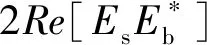
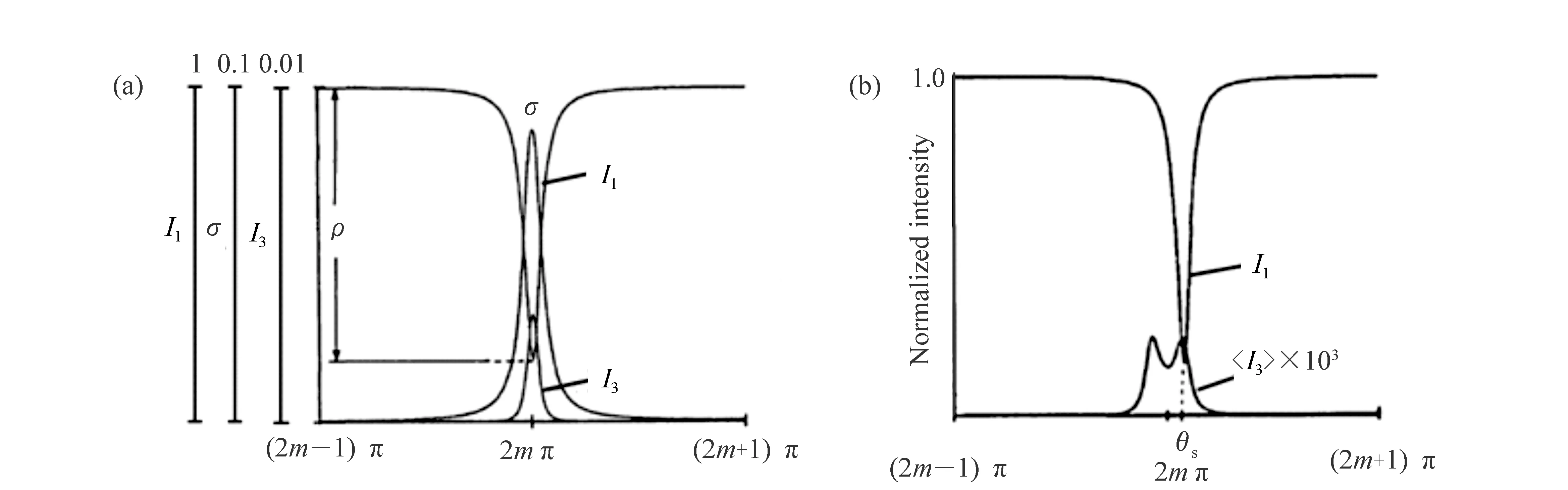
Fig.1 (Color online) Resonance curves of signal light and backscattered light when gyroscope is (a)static or (b)in a rotating state
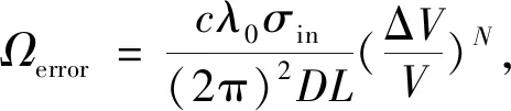
(2)
wherecis the light velocity in vacuum,λ0is the vacuum wavelength,σinis the Rayleigh backscattering coefficient in the WRR,Dis the diameter of the WRR,Lis the waveguide resonator length of the WRR, ΔV/Vis the suppressed carrier voltage error. Suppressing the carrier components is important for reducing the gyro output bias error.
3 Three phase modulation techniques
Phase modulation techniques of the RIOG are applied to overcome the backscattering/backreflection noise in the resonator and to improve the detection sensitivity. Of course, not all phase modulation techniques are introduced in this paper. In fact, these techniques presented in the next section are considered to be the most effective methods for improving the performance of the RIOG.
3.1 Single-phase modulation technique
Since the phase modulation technique for eliminating the effect of Rayleigh backscattering was proposed by K. Iwatsuki in 1984, people have paid more and more attention to it. Single-phase modulation is the first generation of phase modulation technology and is shown in Fig.2. Several kinds of signal waves were chosen to drive the phase modulator in a RIOG based on SPMT[16-20,37], which include sinusoidal waves, serrodyne waves, triangular waves and trapezoidal waves. The serrodyne modulation does well in the readout system of the RIOG system, but the pulse caused by the amplitude deviation from 2π will introduce additional bias error in rotation rate sensing. Therefore, we mainly introduce the other three modulation waves.
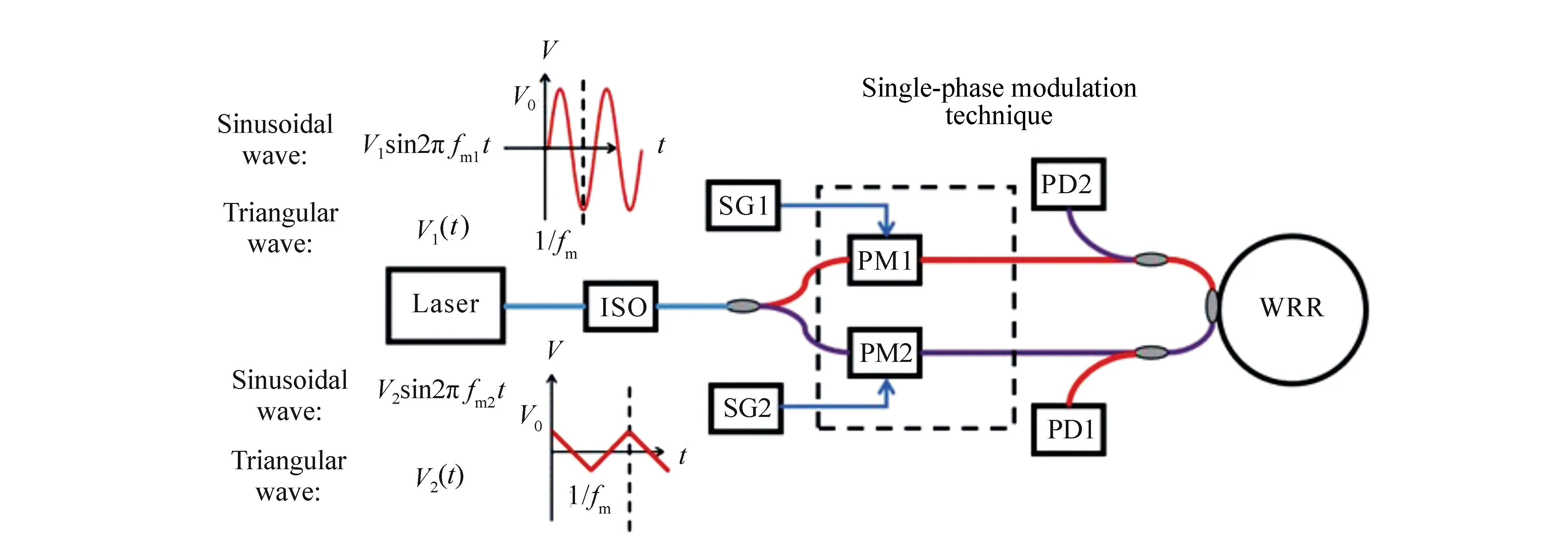
Fig.2 (Color online) Sketch map of single-phase modulation technique
Sinusoidal wave modulation signals can be expressed as:
U=V0sin(2πfmt) ,
(3)
f(t)=f0-Mfmcos(2πfmt) .
(4)
After phase modulation, the laser frequency is centered onf0and varies with cosine. When the laser frequency is equal to the resonant frequency of the WRR (f0=fr), the output peak intensity is equal, as shown in Fig.3(a). When the laser frequency deviates from the resonance frequency of the WRR (f0≠fr), there is a height difference of the output beam intensity between the adjacent peaks, as shown in Fig.3(b). Frequency deviation can be obtained by demodulating the first harmonic component of the output signal and the gyro rotation angular velocity can finally be obtained. Using sinusoidal waves, the normalized amplitude of the carrier component in the CCW direction can be written as
|A0|=|J0(M)| ,
(5)
whereJ0(M) is the first kind of Bessel functions at the zero-th order, andMis the LiNbO3modulation index. When the modulation coefficientMof LiNbO3phase modulator is determined, the normalized amplitude of the carrier component |A0| is the value of the zero-th order Bessel functions of the first kind at pointM. By reducing the carrier component, the interference light intensity between the signal light and backscattered light can be reduced.

Fig.3 (Color online) Theoretical signal light intensity after sinusoidal wave modulation when (a)the laser frequency is equal to the resonant frequency and (b)the laser frequency deviates from the resonance frequency
The tiangular wave modulation signal can be expressed as:
(6)
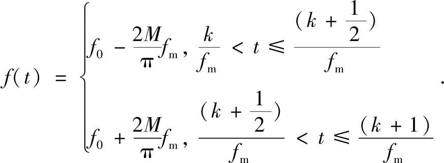
(7)
When the laser frequency is equal to the resonant frequency of the WRR (f0=fr), the laser frequencies after phase modulation are on the resonant frequencyfrsymmetry, as shown by the red line in Fig.4(a). The detector outputs a constant direct current, as shown in the blue line of Fig.4(a). When the laser frequency deviates from the resonance frequency of the resonant ring (f0≠fr), the corresponding output intensity is not equal and the detector outputs a square wave, as shown in the blue line of Fig.4(b). Using triangular waves, the normalized amplitude of the carrier component of the gyro in the CCW direction can be written as
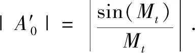
(8)
Generally, the carrier component zero points in Eq.(5) and (8) can be calculated to beM=2.405, 5.52 … for the sine wave phase modulation technique andMt=π, 2π… for the triangle wave phase modulation technique.
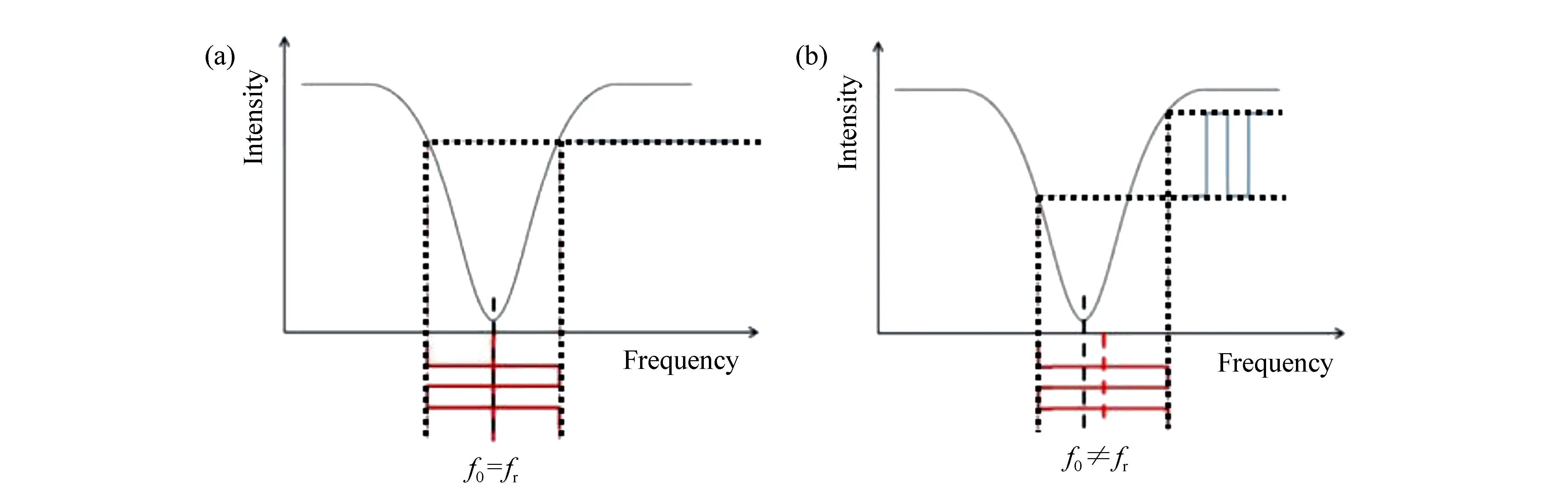
Fig.4 (Color online) Theoretical signal light intensity after triangular wave modulation when (a)the laser frequency is equal to the resonant frequency and (b)the laser frequency deviates from the resonance frequency
When the modulation indexMis not equal to the carrier component zero points, the normalized amplitude of the carrier component using the sinusoidal phase modulation technology increases faster than in the triangular phase modulation, which is shown in Fig.5. In other words, the triangle waveform SPMT is better than the sine waveform SPMT in reducing the backscattering noise.
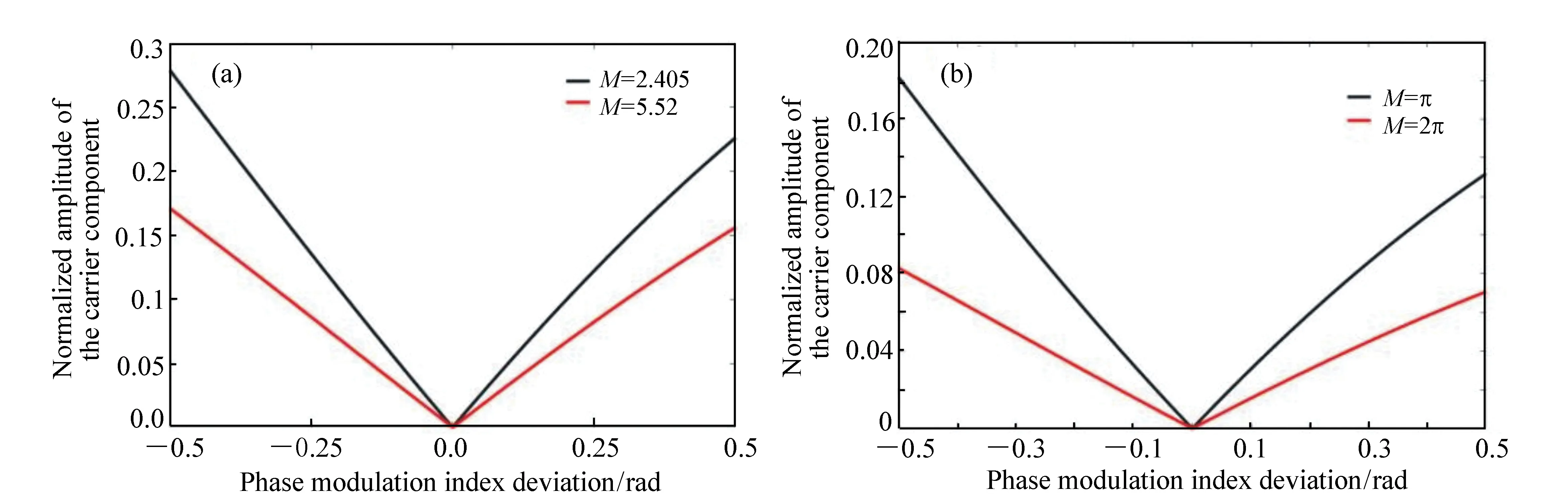
Fig.5 (Color online) Relationship between the phase modulation index deviation from the carrier component zero point and the normalized amplitude of the carrier component. (a)The results of the sine wave SPMT. (b)The results of the triangle wave SPMT[10,17].
Maetal. proposed a RIOG system based on the SPMT using sinusoidal signals[10,38], which is shown in Fig.6(a). By optimizing the amplitude of the sinusoidal signal, the carrier component was suppressed by about 100 dB, and the bias stability was improved to 0.46(°)/s for 50 s with a 7.9 cm long silica WRR. H. Yuetal. proposed an SPMT system using triangular wave signal[17], which is shown in Fig.6(b). Applying an anti-phase triangular wave to modulate the counter-propagating light waves, the RIOG long-term bias stability of 0.717 08(°)/s was achieved with a 12.8 cm long silica WRR. In order to achieve a high carrier rejection ratio in the SPMT system, the amplitude of the modulated signal must be optimized. The amplitude of the phase modulation can be optimized based on the self-heterodyne technique[39]. However, the carrier component suppression level is susceptible to the accuracy of the modulation index and the half-wave voltage of an LiNbO3phase modulator is a temperature-dependent parameter.
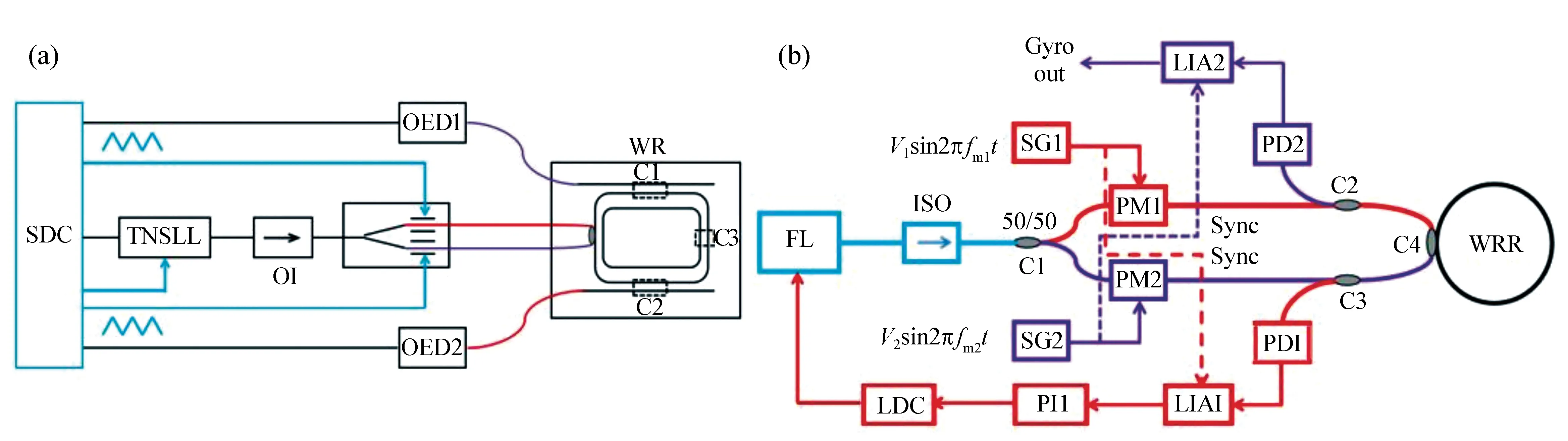
Fig.6 (Color online)Sketch map of the RIOG based on (a)the single triangular phase modulation technique[17] and (b)sketch map of the RIOG based on the single sinusoidal phase modulation technique[10]
Though these two types of phase modulation techniques can achieve a high carrier rejection ratio by optimizing the signal amplitude, they cannot directly reflect the fluctuation information of the observed resonator transfer function. Junjie Wang et al. proposed a RIOG system employing trapezoidal phase modulation[17], which is shown in Fig.7. In the upslope and downslope region, it can be seen as a constant frequency shift for laser light, and the differential of the corresponding resonator outputsI1andI3is proportional to the difference between the frequencies of the laser and the WRR. In the top and bottom regions, it is a zero frequency shift for laser light and the corresponding outputsI2andI4can reflect the real-time output. Using the differential ofI2andI4to compensate the gyro output in real-time, the backreflection noise suppression level and short-term drift can be improved greatly. Consequently, based on a silica waveguide resonator with a diameter of 6 cm and a finesse of 82, a bias stability of 0.09(°)/s with an integration time of 10 s over 3 000 s is achieved.
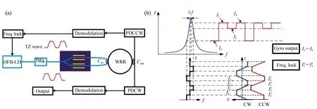
Fig.7 (Color online)(a)Sketch map of the demodulation method of the trapezoidal phase modulation technique[18], (b)intensity modulation output from resonator under trapezoidal phase modulation
3.2 Double phase modulation technique
In order to achieve high modulation amplitude accuracy, the double phase modulation technique was proposed. By increasing the phase modulator, not only did the temperature tolerance increase, but also the modulation accuracy improve. DPMT has two types, one is the double phase modulation technique with the same waveform and the other is a hybrid phase modulation technique.
3.2.1 Double phase modulation technique with the same waveform
There are basically two kinds of double phase modulation techniques, each with identical waveforms. One is the double sinusoidal phase modulation(DSPM) technique[20], and the other is the double triangular phase modulation(DTPM) technique[21].
Maetal. proposed a RIOG based on the DSPM technique, which is shown in Fig.8[19,21]. Phase modulators PM1, PM2, PM3 and PM4 are driven by the sinusoidal waveform by the signal generators SG1, SG2, SG3 and SG4 with modulation frequenciesf1,f2,f3andf4, respectively. Like with the SPMT, frequenciesf1andf3should be different so that they can eliminate the effect of the backscattering itself. PM1 and PM3 are used for gyro signal detection, and PM2 and PM4 are used for additional carrier suppression. As mentioned above, in an SPMT system, the high carrier suppression requires high accuracy of temperature stability and signal amplitude. These stringent requirements can be significantly relaxed by using DPMTs.
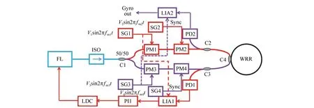
Fig.8 (Color online) Schematic illustration of a RIOG based on the DSPM technique[21]
For a RIOG using the DSPM technique, considering Eq.(5) and additional phase modulator PM3, the normalized amplitude of the carrier component in the CCW direction can be written as

(9)
whereJ0(M1) andJ0(M3) are the first kind of Bessel functions at the zero-th order corresponding to PM1 and PM3, respectively. The additional phase modulator PM3 is connected in series with the phase modulator PM1, so the normalized amplitude of the carrier component of the DSPM technique is the product of the two normalized amplitudes of the carrier component of the sine waveform SPMT. As Ma et al. reported in their paper[21], compared with the SPMT, the accuracy requirement of the modulation amplitude and the temperature stability are relaxed by a factor of more than 30 times to achieve a high suppression ratio of the backscattering noise. The modulation frequencyf1andf3are optimized to obtain max slope of the demodulated curve of SPMT. Besides, Maetal. investigated the influence of the additional phase modulator on the gyro′s performance. The influence off2andf4on gyro signal detection can be neglected when its frequency is smaller thanf1andf3by three orders, respectively. Consequently, a short-term bias stability of 0.01(°)/s is obtained in the polarization maintaining silica waveguide resonator with a length of 7.9 cm.
Yinzhou Zhietal. proposed a DPMT using triangular wave signals to modulate the light signal[20], which is shown in Fig.9. Four triangular waves:V1(t),V2(t),V3(t) andV4(t) are generated by two signal generators SG1 and SG2, whose frequencies aref1,f2,f3andf4, respectively. SignalsV1(t) andV3(t) are used for phase modulation,V2(t) andV4(t) are used to reduce the backscattering noise. To eliminate the random noise produced by the inflection points of the triangular wave[40], the relationships between the four triangular waves′ frequencies should such thatf1=Kf3andf2=Kf4, whereKis an integer. The phase ofV1(t) andV3(t) is set to be the opposite of each other to reduce the influence of the backscattering intensity. In the CCW direction, the demodulation signal is synchronized withV2(t), which is affected by parameterK. When the outside temperature drift ΔTis considered, the carrier component suppression ratio of the DTPM can be derived as

(10)
Further, when the modulation amplitude error ΔVppis considered, the carrier component suppression ratio of the DTPM can be derived as

(11)
where

(12)
ΔTis the temperature drift andkTis the temperature drift coefficient.Vπis the half-wave voltage of the phase modulator;VPP1andVPP2are the modulation amplitude ofV1(t) andV2(t), respectively. In order to relax the requirements of high carrier suppression: modulation amplitude accuracy and temperature stability, a highKvalue is needed. However, a larger value forKwill reduce the frequency ofV3(t), which will degrade the bandwidth of the signal detection and the processing module. A value of 100 is recommended for parameterK. As a consequence, compared with the SPMT using triangular waves, when the carrier suppression is 60 dB, the modulation amplitude error is relaxed from 0.021 7 V to 0.483 5 V which is nearly 30 times greater and the temperature drift is relaxed from 4 ℃ to 127 ℃. When the DTPM is applied in the RIOG, a bias stability of 0.22(°)/s is achieved for 1 h.
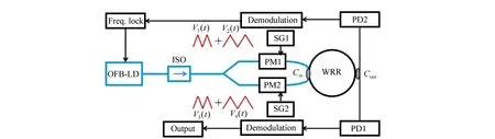
Fig.9 (Color online)Schematic illustration of a RIOG based on the DTPM[20]
When the RIOG is applied with anti-phase triangular phase modulation, the backreflection and backscattering induced errors can be suppressed, but the angle random walk(ARW) of the RIOG is not correspondingly reduced[41,20]. Wang et al. proposed a RIOG based on the phase difference traversal(PDT) method[22], which is shown in Fig.10. The PDT method is a type of in-phase modulation technique[40], that can eliminate the ripples caused by backreflection and reduce the AWG of a gyro.f0is the primary phase modulation(PPM) signal. The frequencies′ difference in the secondary phase modulation(SPM) signalf1andf2varies with time to achieve phase difference tranversal. According to reference [22], the frequencies of the SPM signal should be not only higher than the sampling rate but also much lower than the frequency of the PPM signal. The amplitude of the SPM signal should also be equal to the full-wave voltage of the phase modulator. Because the zero-bias fluctuation caused by backreflection is a periodic fluctuation of the phase difference of the counter-propagating waves, the spectrum of backreflection error signal can be transmitted from the low frequency band to the high frequency band by PDT method. After passing the low pass filter, backreflection error signals can be reduced greatly. With the multi-wave hybrid phase modulation scheme shown in Fig.10(c), the PDT process will change more rapidly and the gyro′s output will be more accurate. Consequently, using a silica waveguide resonator with a diameter of 6 cm and a finesse of 82, the RIOG short-term bias stability and long-term bias stability reached 0.005 5(°)/s and 0.012(°)/s, respectively.
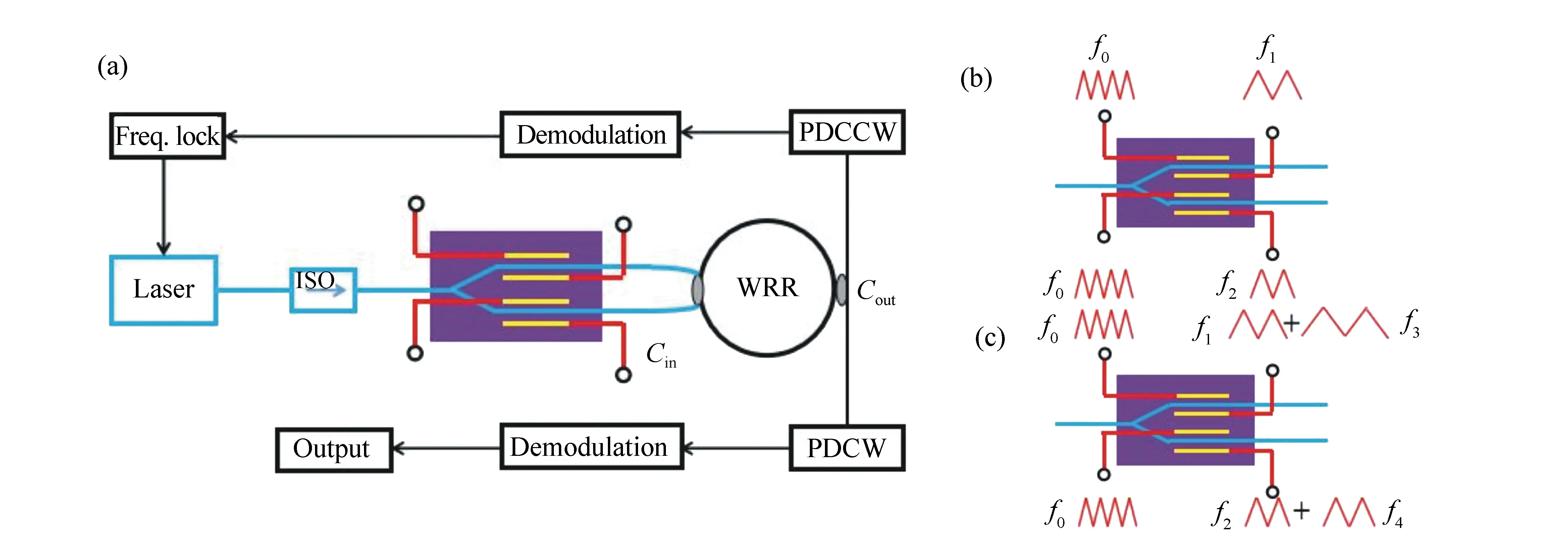
Fig.10 (Color online) Schematic illustration of a RIOG based on the phase difference traversal(PDT) method[22]
3.2.2 Hybrid phase modulation technique
In recent years, a new phase modulation technique called the hybrid phase modulation technique has been proposed and has attracted greatly attention[7,23-24,42]. This new hybrid phase modulation technique is based on the following principle:by combining a lower frequency modulation waveform with a different kind higher frequency modulation waveform, a very high carrier suppression ratio can be attained. It should be noted that the RIOG output signal is read by the lock-in amplifier, which is based on the correlation detection principle[43]. The lightwave after modulation includes many harmonic components. The gyro detection rotation signal is only demodulated by the first harmonic component. However, the odd multiples of the modulation frequency have been proven to be less responsive, which will deteriorate the gyro′s output. Maetal. proposed a hybrid digital phase modulation technique as shown in Fig.11. The RIOG long-term bias stability was improved by 0.05(°)/s for the integration time is 400 seconds for 1 hour with a WRR, whose radius length is 7.9 cm[23]. The sinusoidal waves added to the phase modulator PM2 are used for additional carrier suppression. The laser frequency in the CCW direction is shifted by digital sawtooth-waves to achieve the second closed-loop. When one step′s time is equal to the digital-to-analogue converter′s(DAC) output rise time, the sideband suppression is maximized. Fengetal. proposed an HPMT scheme based on triangular phase modulation with one more sawtooth-wave modulation in each direction[7]. With one more sawtooth-wave modulation, the remaining odd harmonic components will be shifted, which mitigates the gyro′s error. A short-term bias stability of 0.22(°)/s for 10 seconds of integration time in 100 s has been carried out in a RIOG with a WRR of a length of 12.8 cm and a finesse of 59.

Fig.11 (Color online) Schematic diagram of the closed-loop RIOG based on the hybrid digital phase modulation scheme. (a)The modulation waveforms are sinusoidal and sawtooth waves[23]. (b)The modulation waveforms are triangular waves and sawtooth waves[7]
4 Summary of phase modulation techniques
As first-generation technology, SPMT has an obvious advantage with just two phase modulators. It is simple and suffers lower optic loss[44]. However, it should be noted that each optical element added to the optical circuit will bring additional insertion loss. However, the use of this technology has an inevitable drawback. The carrier suppression level is susceptible to the modulation amplitude accuracy. The carrier suppression will be decreased when the temperature drifts.
The double phase modulation techniques with the same waveform introduced by Maetal. and Zhietal. have aroused widespread concern. They can easily achieve high carrier suppression and backscattering error can be easily reduced to below the shot noise limited sensitivity of the RIOG[42]. The modulation amplitude accuracy and the temperature stability are also greatly relaxed. However, the techniques make the resonator′s response more complicated. The additive effect of additional modulation should be taken into account.
Using HPMT can reduce the gyro′s error with the additional suppression of an unwanted harmonic component. HPMT proposed by Maetal. can set up a double closed-loop RIOG, which will offer a wider dynamic range and better linearity[23]. Moreover, it is beneficial in field programmable gate array(FPGA) applications[45]. However, it still can′t reach carrier suppression levels as high as double phase modulation techniques with the same waveform. Recently, Liuetalproposed that carrier suppression can be further improved by using the sideband locking technique[27]. The carrier component and backscattering noise are both suppressed using the resonance characteristics of the WRR. This modulation technique does not require a highly accurate modulation coefficient and is not limited by the performance of the device. In order to clearly portray the stage of these researchers′ development, basic features of the RIOG based on different phase modulation techniques with the best bias stability are summarized in Tab.1. The RIOG with the best experimentally measured performance is based on the sideband locking technique[27]. As is shown in the table, RIOGs based on the phase modulation technique exhibit performance that is still far from the demands of the defense and the aerospace industry. Therefore, other optical noise in RIOGs, such as Kerr noise, polarization fluctuation noise and normal modes loss difference, must still be further suppressed to improve the RIOGs′ long-term stability.
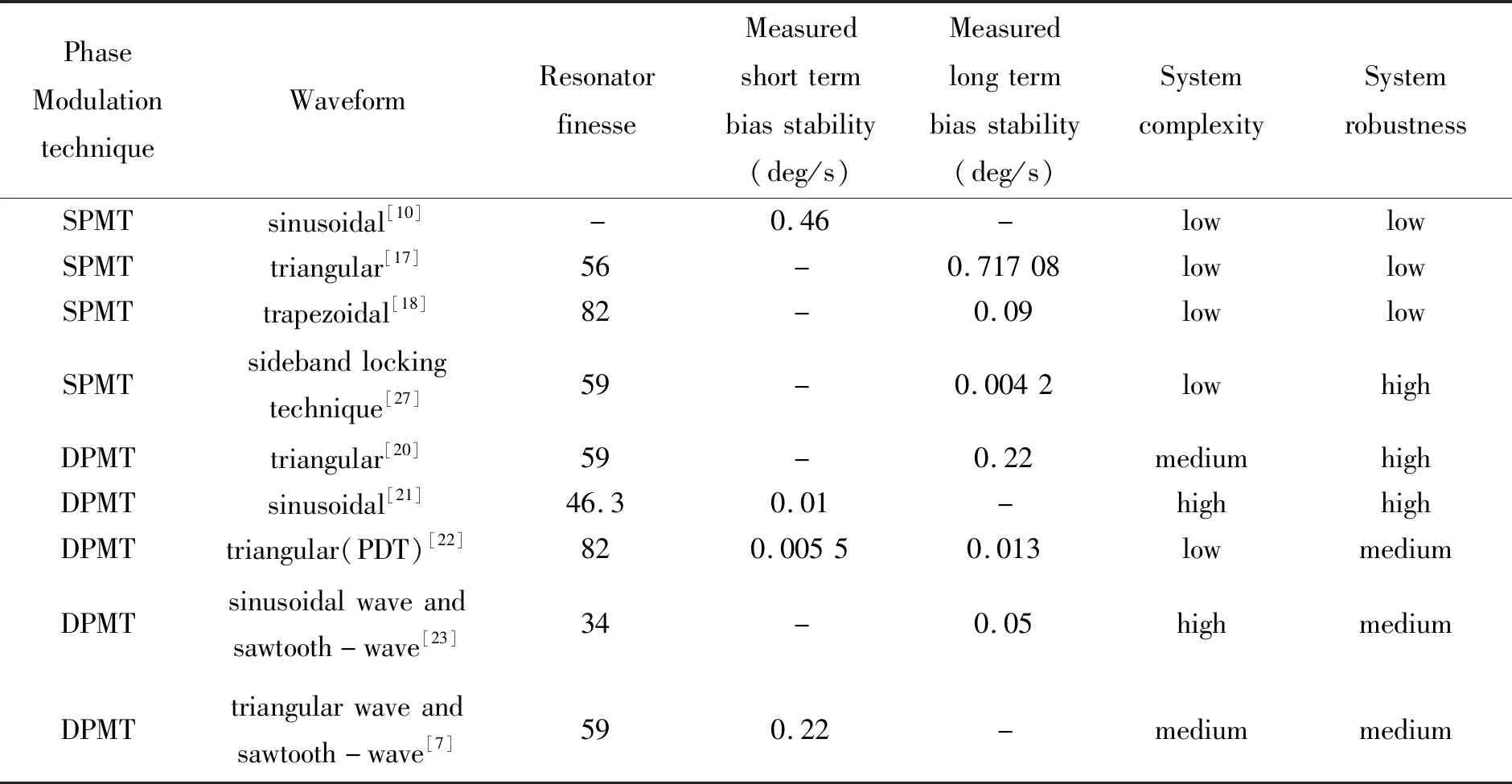
Tab.1 RIOGs based on different phase modulation techniques with the best bias stability
5 Conclusion
Over the past few years, phase modulation techniques have been widely used in RIOG applications. Backscattering noise in RIOGs has been greatly reduced through efforts to optimize phase modulation techniques. This paper aims to classify the various techniques, to review each scheme, and to compare their advantages and limitations. In this paper, several recent phase modulation techniques were investigated. SPMTs are simple and effective modulation techniques. However, it can be easily disturbed by environmental temperature. DPMTs can further improve accuracy and system robustness. Nevertheless, this makes the resonator′s response more complicated. The higher precision sideband locking technique is likely to be the mainstream research project in the future. Overall, the performance of RIOGs is still far from satisfying the needs of aerospace and defense applications. Therefore, more research efforts are still needed to suppress the main noises in RIOGs, including backscattering/backreflection noise, polarization noise, and to improve the performance of RIOGs.