
Effects of the transverse electric field on nanosecond pulsed dielectric barrier discharge in atmospheric airflow
2020-06-14 08:45YongfengXU徐永锋HongfeiGUO郭宏飞YuyingWANG王玉英ZhihuiFAN樊智慧andChunshengREN任春生
Plasma Science and Technology 2020年5期
Yongfeng XU (徐永锋),Hongfei GUO (郭宏飞),Yuying WANG (王玉英),Zhihui FAN (樊智慧) and Chunsheng REN (任春生),†
1 Key Laboratory of Materials Modification by Laser,Ion,and Electron Beams,Dalian University of Technology,Dalian 116024,People’s Republic of China
2 School of Science,Hebei University of Engineering,Handan 056038,People’s Republic of China
† Deceased.
Abstract
Keywords:dielectric barrier discharge,high-voltage,atmospheric pressure air,airflow,lowtemperature plasma,nanosecond pulsed discharge
1.Introduction
Dielectric barrier discharge (DBD) is a typical method for generating non-equilibrium plasma at atmospheric pressure.Due to its moderate electron temperature and plasma density,it has been widely used for a variety of industrial applications,such as ozone generation,environmental treatment,surface modification,and plasma display panels[1–5].DBD is usually driven by a pulse power supply or alternating current (AC)power source with a frequency from tens of hertz to several tens of kilohertz.Compared with the DBD excited by an AC power source,the nanosecond pulsed DBD is more diffuse[6],which is mainly ascribed to the over-voltage breakdown based on the fast rising time in tens of nanosecond scale [7,8].This results in a larger reduced electric field E/N (where E is the electric field,N is the density of neutral particles),which can generate higher energy electrons and numerous electron avalanches simultaneously [7,9].In addition,nanosecond pulses can improve the discharge stability when the narrow duration of pulses is shorter than the characteristic time needed for the development of discharge instability [10].Therefore,a nanosecond pulse power supply is used to excite the discharge in our experiment due to the above advantages.
Although a nanosecond pulse power supply makes it possible to realize uniform discharge under strict conditions,such as a narrow gap[8],DBD usually presents a filamentary discharge.The reason is that the Pd value (product of gas pressure P and gas gap d) is so large at atmospheric pressure that the local space charge field formed by the space charge separation can be compared to the applied electric field [11].However,our previous work reported that the diffuse discharge started from the electrode edge and moved toward the downstream region under the effect of airflow,which led to the diffuse discharge in the whole discharge space[12].It was found that there was a filamentary discharge in the central region of the electrode and a diffuse discharge at the electrode edge.This was mainly attributed to the existence of the edge effect [13–15].Most researchers believe that the diffuse discharge at the electrode edge is mainly ascribed to the stronger electric field or the local field enhancement effect [16,17].For example,it was found by Okazaki et al that uniform discharge can be generated by using metal wire meshes as electrodes covered by polyethylene terephthalate,and the discharge was affected by the flatness of the metal wire meshes [18].Other works have also reported that uniform discharge could be obtained under the same wire mesh electrodes [19,20].They pointed out that the generation of uniform discharge was ascribed to the field enhancement which initiated a corona discharge and provided seed electrons.Liu et al found that the floating electrode could improve the uniformity of discharge due to the stronger electric field,which is beneficial for generating the initial discharge,and resulted in sufficient and evenly distributed initial electrons[21].It has been found that a bright ring first appears at the electrode edge and then moves from the edge to the inside,and the result agrees well with a 2D simulation that showed that the electric field at the electrode edge increased and resulted in a more intense discharge[22].Duan et al reported that the pattern shape was consistent with the shape of the electrode.But they did not provide an explanation for the role of the edge effect in pattern formation [13].For the diffuse discharge at the electrode edge,less attention has been paid to the influence of the transverse electric field on discharge[12,23].It has been reported in previous work that the transverse electric field at the electrode edge is responsible for the generation of diffuse discharge[12].Therefore,the effects of the transverse electric field on discharge are investigated.
In this paper,an asymmetric electrode geometry is proposed to enhance the transverse electric field.To further explore the influence of the mechanisms of the transverse electric field on discharge,the electrical characteristics,discharge images,movement characteristics of the micro-discharge channel,and optical emission spectra (OES) are analyzed.
2.Experimental setup

Figure 1.Schematic diagram of the experimental setup.(a) Symmetric geometry where the high-voltage and grounded electrodes are aligned,(b) asymmetric geometry where the transverse electric field is in the same direction as the airflow,(c) asymmetric geometry where the transverse electric field is opposite to the airflow.
A schematic diagram of the experimental setup is presented in figure 1.The working gas is room air.The electrode geometry(a)is a symmetric electrode structure.Electrode geometries (b) and(c) are the asymmetric electrode structures in order to obtain a transverse electric field component.The only difference between them is the direction of the transverse electric field.The highvoltage and grounded electrodes are in the x-y plane,and the electrodes are only staggered in the y-direction.Therefore,the transverse electric field component is along the y-direction,and the longitudinal electric field component is along the z-direction.A transparent indium tin oxide (ITO) and an aluminum foil,covered by quartz plates with a thickness of 2 mm,are used as the high-voltage and grounded electrodes,respectively.The aligned area of the high-voltage and grounded electrodes is 100 × 50 mm2.The displacement distance between the highvoltage and grounded electrodes is 20 mm.The discharge gaps are varied from 4–6 mm.A repetitive nanosecond pulse power supply applied to the high-voltage electrode can generate pulse voltage with a rising time of 40 ns and a full width at half maximum of 200 ns,which is used to ignite the discharge.The voltage regulator connected to the nanosecond pulse power supply can be used to adjust the voltage amplitude input to the DBD circuit.The pulse repetition frequencies (PRFs) of the nanosecond pulse power supply are adjusted at the fixed values of 100,300,600,1000,and 1200 Hz.In all cases,the discharges are excited by the same voltage waveform and amplitude of 31.5 kV.The applied voltage and total current are measured by a high-voltage probe(Tektronix P6015 A,bandwidth 75 MHz)and a current probe (Pearson 6600,bandwidth 120 MHz),respectively.And a digital oscilloscope (Tektronix DPO4104,bandwidth 1 GHz,sampling frequency 5 GS s-1)is used to record and store these waveforms.The OES are directly measured by the spectrometer equipped with a CCD detector (Acton Research Spectrum 2500i),which is calibrated with a Hg lamp.The entrance slit opening of the monochromator is 500 μm.The resolution of the spectrum measurement system is 0.013 nm.The grating groove is 2400 lines/mm with a glancing wavelength at 240 nm.The integration time is 20 ms.The distance between the optical fiber and the DBD reactor is fixed at 35 mm.The collimator is placed on the fiber head to ensure that the OES can be measured at a local area and realized spatial resolution.Location 1 at the central region of the electrode is selected to represent the aligned region,location 2 where the fiber is tangent to the electrode edge represents the misaligned region,and location 3 indicates the electrode edge.The reason will be given in section 3.1.3.The airflow system consists of an air pump serving as the source of airflow and a self-designed wind tunnel used for introducing airflow to the discharge gap.A pitot tube connected with a pressure differential gauge(Testo512,200 hPa)is placed at the central position of the wind tunnel outlet.The airflow velocity can be changed and displayed on the pressure differential gauge by adjusting the valve on the wind tunnel,and the valve positions corresponding to the different airflow velocities are marked in advance.Airflow parallel to the electrode along y-direction ranges from 0–40 m s-1.Accordingly,the transverse electric field of the electrode geometry (b) is in the same direction as the airflow and the transverse electric field of the electrode geometry (c) is opposite to the airflow.Top-view and side-view discharge images are captured by a digital camera(Nikon D7000) and a high speed motion analyzer (Phantom V1610).The side-view discharge images are taken in the x-direction.
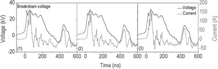
Figure 2.The applied voltage and total current waveforms of different electrode structures under a 5 mm discharge gap and a 1000 Hz PRF.(1) Electrode geometry (a),(2) electrode geometry (b),(3) electrode geometry (c).
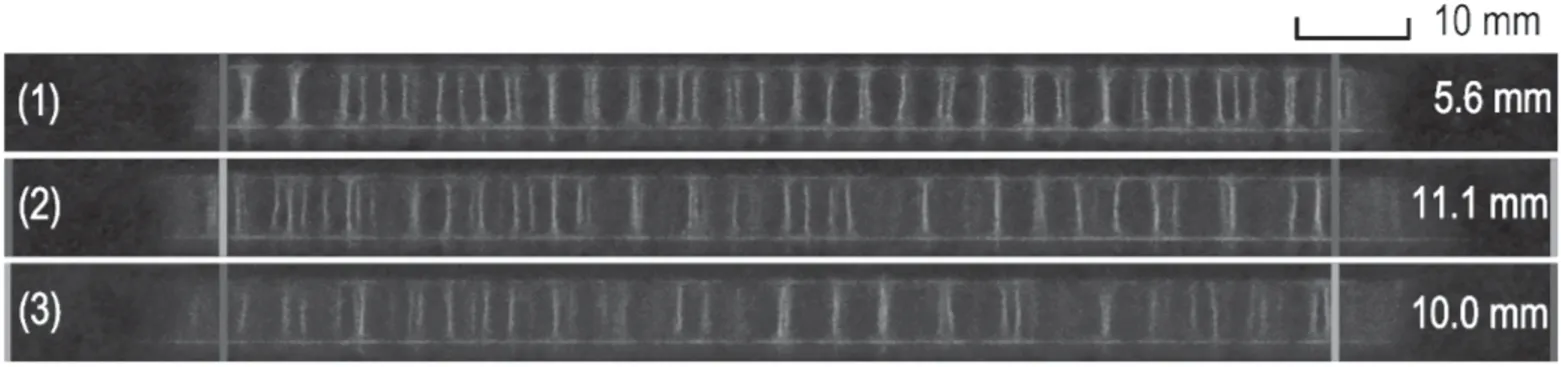
Figure 3.Side-view images of the discharge of different electrode structures.The exposure time is 1/1000 s.(1) Electrode geometry (a),(2) electrode geometry (b),(3) electrode geometry (c).
3.Results and discussion
3.1.Comparison of the discharges between the different electrode structures in static air
3.1.1.Electrical characteristics.When the discharge gap is 5 mm and the PRF is 1000 Hz,the applied voltage and total current waveforms of different electrode structures are presented in figure 2.It can be seen that the applied voltage and total current waveforms of different electrode structures are almost the same.A sudden drop at the rising front of the applied voltage is about 20 ns.It is usually considered a sign of gas breakdown,which is ascribed to the sudden increase of the discharge current and insufficient output power of the nanosecond supply when the gas breaks down[24].The total current peak occurring at around 48 ns is about 166 A.The total current is composed of the conduction current,displacement current,and electromagnetic interference [25].The displacement current and electromagnetic interference exhibit little difference due to a less misaligned region compared with the aligned region.And the conduction current is mainly contributed by the discharge of the aligned region,and accordingly,the conduction current is almost identical due to the same aligned regions between the different electrode structures.
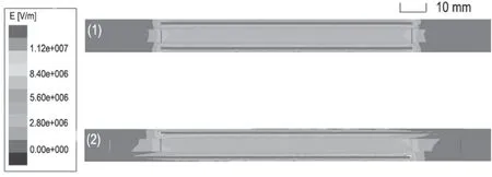
Figure 4.Simulated spatial distributions of the electric field intensity of different electrode structures.(1) Electrode geometry (a),(2) electrode geometry (c).
3.1.2.Discharge images.Although the electrical characteristics are almost the same for the different electrode structures,there is a difference in the side-view discharge images given in figure 3 under the same experimental conditions.The DBD reactor is in static air.The exposure time is 1/1000 s,which is equal to one discharge cycle.The edge locations of the high-voltage and grounded electrodes are marked with red lines and green lines,respectively.It can be seen that the discharge at the electrode edge is more diffuse than that at the electrode center for the symmetric electrode geometry,and the diffuse discharge manifests in the misaligned region for the asymmetric electrode geometries.A filamentary discharge is composed of numerous short-lived micro-discharge channels,which are randomly distributed in space and time.It is found that the diffuse discharge has a more uniform emission or luminescence without any bright spots or an irregular distribution pattern compared with the filamentary discharge,or it means that no bright filaments can be distinguished.The difference between the filamentary discharge and the diffuse discharge is visually distinguishable.In general,for the AC discharge,the current waveform can be used to categorize the different regimes of DBD[18].In this case the current waveform of the filamentary discharge shows multi-current peaks,while the current waveform of the uniform discharge presents a current peak.However,for the nanosecond pulsed DBD,the different discharge states cannot be distinguished by using electrical properties,because the current waveform shows only one current peak for both the filamentary discharge and the diffuse discharge.The generation of the diffuse discharge is attributed to the more uniform distribution of the space charges induced by the transverse electric field.For the symmetric electrode geometry,on the one hand,the electric field at the electrode edge is stronger than that in the central region [17,22],which can generate more electron avalanches.On the other hand,it has been reported that there is a transverse electric field component at the electrode edge [12,23].The spatial ions in the microdischarge channels at the electrode edge have a transverse movement under the effect of the transverse electric field,and drag the surface electrons through an electrostatic coupling force,which leads to the redistribution of the space charges.The combined effects,which are the simultaneous generation of more electron avalanches and the redistribution of the space charges,result in the spatial overlap of the electron avalanches and the smoothness of the space charge field gradient.Thus the excessive development of single electron avalanches into the streamer can be inhibited,which is conducive to the generation of diffuse discharge [26].The reasons for the presence of the diffuse discharge in the misaligned region of the asymmetric electrode geometries are analogous.
To certify that the generation of the diffuse discharge is caused by the transverse electric field,the spatial electric field intensity distributions of electrode geometries (a) and (c) are simulated by using Ansoft Maxwell software,as shown in figure 4.This method has been used in previous works[21,27,28].In this model,all the simulation parameters are the same as those in the experiment.The high-voltage and grounded electrodes are applied with voltages of 31.5 kV and 0 V,respectively.It can be seen that the electric field intensity distributions at the electrode edges and misaligned regions are not uniform,and there is a transverse electric field component in these regions.Although it is difficult to determine the quantitative intensities of the electric field and the transverse electric field component,the relative intensity between them can be qualitatively compared.They correspond to the phenomena of the discharge images in figure 3,which confirm our analysis of the experimental results.
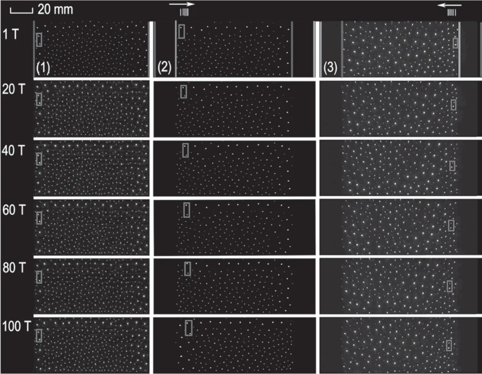
Figure 5.Temporal evolution of the discharge with a 1/1000 s exposure time.PRF=1000 Hz,discharge gap=6 mm.1 T represents the first discharge cycle,and the time interval is 1 T=1 ms.(1)Electrode geometry(a),(2)electrode geometry(b),(3)electrode geometry(c).
In addition,it is concluded from figure 3 that the length of the diffuse discharge region along the direction of the transverse electric field for the asymmetric electrode geometries is longer than that for the symmetric electrode geometry.The lengths of the diffuse discharge region are integrated directly into the captions of figure 3.The length of the diffuse discharge region is considered to be related to the moving velocity of the space charges.Therefore,the moving characteristics of the micro-discharge channel are studied by using the discharge temporal evolution images taken by a high speed motion analyzer.The results are shown in figure 5 with a 6 mm discharge gap.The exposure time is 1/1000 s and the sample rate is 1000 frames per second (fps) for the 1000 Hz PRF.The starting time is 1 T,representing the first discharge.The time interval of 1 T is equal to 1 ms.The cycle corresponding to each discharge image is marked.The two micro-discharge channels marked with red squares are selected and traced frame by frame in figure 5,which are both located at the high-voltage electrode edge.According to the invariance of the relative position between the two microdischarge channels,the two micro-discharge channels marked with red squares in each cycle are considered to be identical.Therefore,the positions of the two micro-discharge channels in the sequential discharge images can be identified.First,the temporal evolution of the discharge images show that the bright micro-discharge filaments manifest in the aligned region,while there is no diffuse discharge in the misaligned region,which is consistent with figure 8 in section 3.2.The diffuse discharge is not obvious,and the relatively weak luminescence intensity of the diffuse discharge cannot be photographed under a larger discharge gap,which leads to no diffuse emission.Then it can be found from figure 5 that the micro-discharge channel of the symmetric electrode geometry is stationary,and the micro-discharge channel moves along the direction of the transverse electric field for the asymmetric electrode geometries.It is found that the movement of the micro-discharge channel is the migration from a point to another in the adjacent discharge cycle [12].For the symmetric electrode geometry,the residual charges generated by the previous discharge always maintain the same position,and the subsequent micro-discharge channel remains at the same location where the residual charges occurred due to the memory effect[5,29,30].The memory effect refers to the influence of the residual charges that survived the previous discharge on the subsequent discharge [31].Although the lifetime of the micro-discharge channel was on the order of 100 ns or less [32,33],it took about 30 min to remove the surface charges [34].The space charges that survived the previous discharge were abundant when the next discharge came [29].Thus the micro-discharge channel appears to be stationary.For the asymmetric electrode geometries,the transverse electric field in the misaligned region as the driving force breaks the equilibrium of the forces between the microdischarge channels,and the repulsive force on the space charges of the aligned region compels the movement along the direction of the transverse electric field.Accordingly,the memory effect is broken.When the next pulse arrives,the micro-discharge channel occurs at the new position where the space charges migrate.The space charges are almost stationary due to the memory effect of the symmetric electrode geometry.However,the space charges move directionally under the effect of the transverse electric field force for the asymmetric electrode geometries.Consequently,there is a longer distance of transverse migration of the space charges during the same time interval,which results in the increase of the length of the diffuse discharge region along the direction of the transverse electric field.
In summary,the transverse electric field is responsible for the generation of the diffuse discharge.The length of the diffuse discharge region along the direction of the transverse electric field is related to the migration of the space charges induced by the transverse electric field.
3.1.3.Optical emission spectra.To estimate the plasma gas temperature and electron density,the OES of the three locations are measured with a 5 mm discharge gap and a 1000 Hz PRF.It can be concluded from figure 3 that the discharges at the electrode edges and the misaligned electrode regions are more diffuse than those in the central region.Therefore,the three locations shown in the experimental setup are selected to measure the OES.In order to reduce errors,each group of data is recorded three times under the same conditions.According to a simplified collision-radiation model,the relative intensity ratio of 371.1 and 380.5 nm(I371.1nm/I380.5nm) can be used to calculate the average electron density ne[35–37].The relationship between
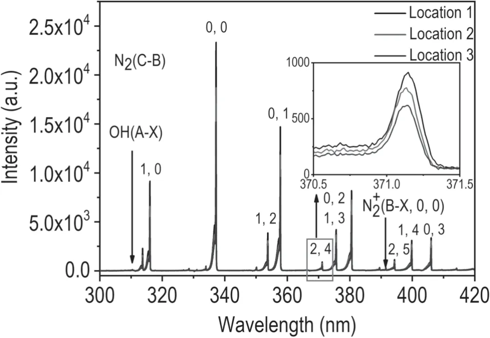
Figure 6.The OES at three locations with a 5 mm discharge gap and a 1000 Hz PRF.
where C0,C1,and C2are constant,n is the degree of ionization,and Ng=2.5 × 1019cm–3is the number density of the neutral particles at atmospheric pressure.According to the OES shown in figure 6,the range of I371.1nm/I380.5nmat locations 1,2,and 3 is 0.109 ± 0.003,0.107 ± 0.001,and 0.110 ± 0.001,respectively.This is similar to the previous work where the value of I371.1nm/I380.5nmis about 0.118,and the calculated neis about 1.72 × 1011cm–3[38].It can be concluded that the electron density at the electrode edge is slightly higher.When the electric field at the electrode edge is stronger,electrons collide and ionize neutral particles to generate more electrons.
Due to a small energy gap between the rotational levels,the equilibrium between the translational motion and the rotational motion is easily achieved by frequent collisions between the heavy particles at atmospheric pressure [39].The plasma gas temperature is approximately equal to the rotational temperature of N2.By comparing the measured spectrum of N2(C3∏u→B3∏g,0 -2)with the simulated spectrum provided by the Specair software,the rotational temperature of N2can be obtained [40,41],as shown in figure 7.It is noted that the rotational temperature of N2at different locations is almost the same.This indicates that the plasma gas temperature is nearly constant in the discharge space.
3.2.Comparison of discharges under different discharge gaps in static air

Figure 7.The measured and simulated OES of N2(C3∏u→B3∏g,0 -2 )with a 5 mm discharge gap and a 1000 Hz PRF.(1)Location 1,(2) location 2,(3) location 3.
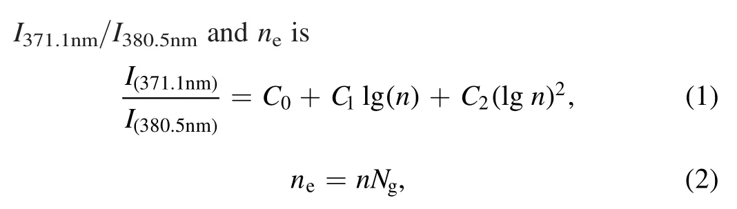
In order to verify the effects of the transverse electric field on the discharge,the discharges under different discharge gaps are studied.Figure 8 shows side-view discharge images of different electrode structures when the discharge gaps are fixed at 4,5,and 6 mm.The PRF is 1000 Hz,and the corresponding exposure time is 1/1000 s.It can be seen that the diffuse discharge area in the misaligned region increases with the decrease of the discharge gaps.The lengths of the diffuse discharge region are integrated directly into the captions of figure 8.Based on the above analysis,the diffuse discharge area depends on the characteristics of the movement of the space charges during the same time interval.Therefore,the moving velocity of the micro-discharge channel is calculated by u=L/Δt,where L is the length of the path of the movement obtained by the images of the evolution of the discharge,and the time interval Δt between adjacent discharge images is fixed at 20 T.The time interval 1 T is equal to 1 ms.Accordingly,the calculated moving velocity of the micro-discharge channel is the time-average velocity per 20 discharge cycles.The initial positions of the tracked microdischarge channel under different discharge gaps are invariant,starting at the electrode edge.Since it is known from figure 5 that the micro-discharge channel of electrode geometry (a) is stationary,and the characteristics of the movement of the micro-discharge channel in the electrode geometries (b) and (c) are the same,only the moving velocities of the the micro-discharge channel for the electrode geometry(c)are calculated,as shown in figure 9.It is shown that the moving velocity of the micro-discharge channel increases with the decrease of discharge gaps.When the applied voltage is kept consistent,the magnitude of the electric field depends on the discharge gap.A higher applied electric field can generate many extra micro-discharge channels [42],and the magnitude of the transverse electric field component in the misaligned region increases in a smaller discharge gap.Consequently,the effect of the transverse electric field force on the space charges in the micro-discharge channel is enhanced,which leads to a larger moving velocity of the space charges.The result is that the space charges have a longer transverse migration distance.The result is similar to the previous work where the length and the propagation speed of filaments increased with VP[43].A more uniform space charge distribution can be formed in a larger region,and a stronger longitudinal electric field component can maintain the discharge over a longer distance.It is also proved that the diffuse discharge area in the misaligned region lies on the moving velocity of the space charges.
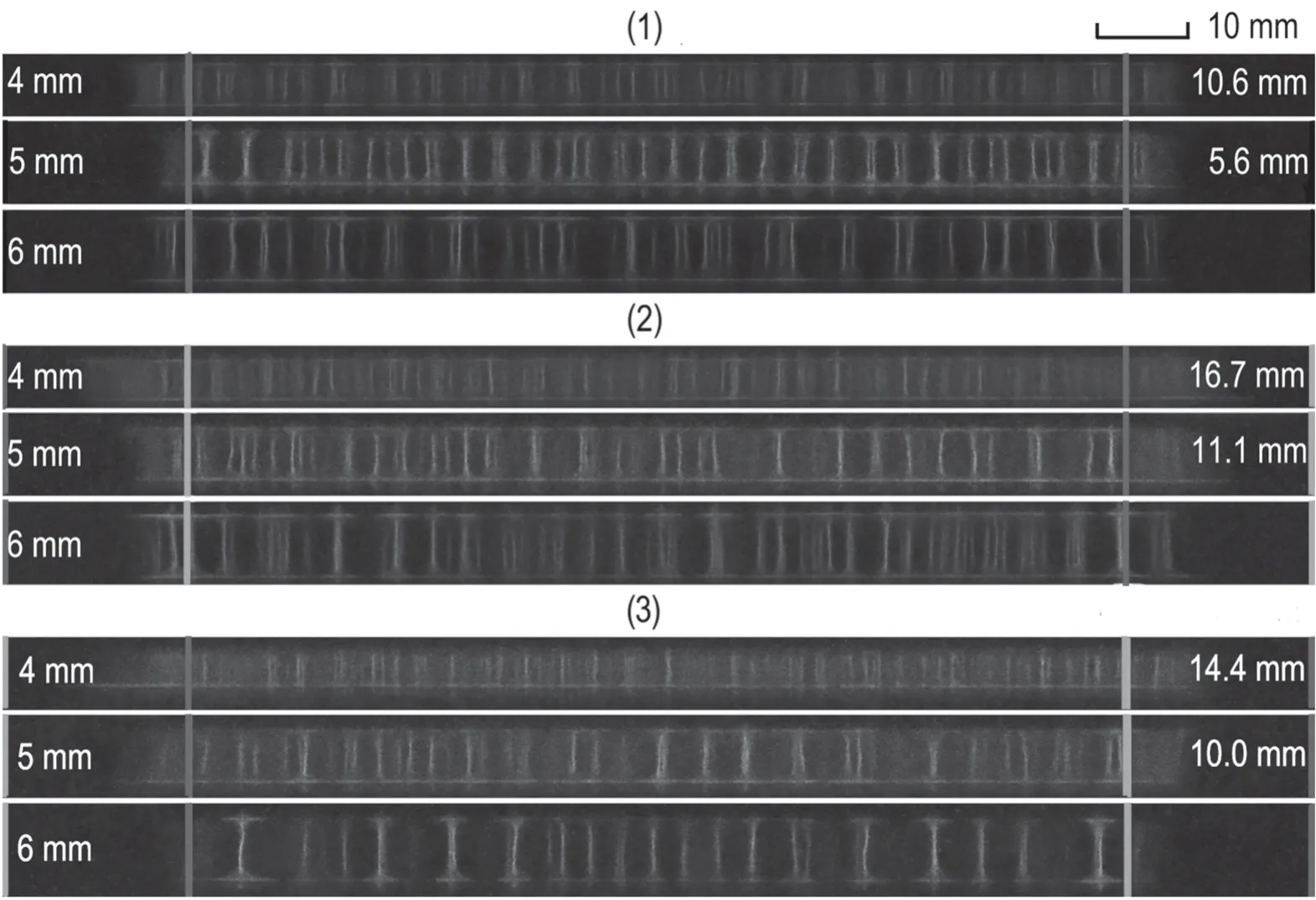
Figure 8.Side-view images of the discharges of different electrode structures under different discharge gaps and a PRF of 1000 Hz.The exposure time is 1/1000 s.(1) Electrode geometry (a),(2) electrode geometry (b),(3) electrode geometry (c).
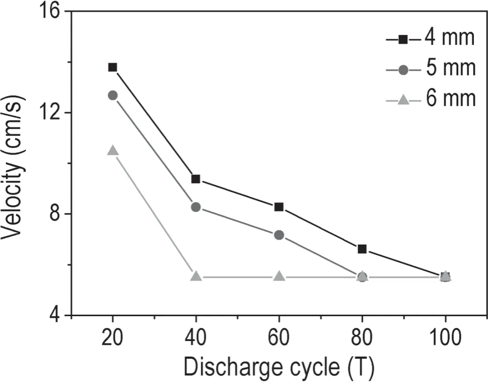
Figure 9.The variation of the moving velocity of the microdischarge channel for the electrode geometry (c) under different discharge gaps and a PRF of 1000 Hz.
At the same time,it is summarized in figure 9 that the moving velocity of the micro-discharge channel decreases with time.The transverse electric field only acts on the space charges in the misaligned region,which are repelled by the space charges from the aligned region.Thus their movement will be hindered.When the space charges accumulate continuously in the aligned region,the obstacles to the space charges in the misaligned region increase.Therefore,the moving velocity shows a downward trend.
3.3.Comparison of discharges under different PRFs in static air
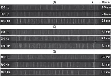
Figure 10.Side-view images of the discharges of different electrode structures with a 5 mm discharge gap under different PRFs.(1)Electrode geometry (a),(2) electrode geometry (b),(3) electrode geometry (c).
The effects of the transverse electric field on discharge can also be illustrated by comparing the discharges under different PRFs.Figure 10 shows side-view images of the discharge of different electrode structures with a 5 mm discharge gap.The values of the PRF are selected as,i.e.100,600,and 1000 Hz,and the exposure time corresponds to 1/100,1/640,and 1/1000 s,respectively.It can be observed that the diffuse discharge area of the misaligned region at a low PRF is larger than that at a high PRF.The lengths of the diffuse discharge region are integrated directly into the captions of figure 10.The PRF is an important parameter of a nanosecond pulsed DBD,and its effects on the discharge characteristics have been extensively investigated[38,44,45].The memory effect presented by the residual particles is the characteristic of repeated pulse breakdown,and it can affect the development of the next breakdown[26,44].On the one hand,the memory effect is more obvious,since the time interval of two consecutive pulses is shorter under a higher PRF[46].The space charges almost remain at the position where the previous discharge occurred during the shorter time,which causes the next discharge to appear at the location of the previous discharge.When the PRF is low,the space charges have enough time to spread during the longer time interval of two consecutive pulses.The distribution of the space charges is more uniform in a larger region where the space charges spread.On the other hand,based on the above analysis,the diffuse discharge area depends on the moving characteristics of the space charges during the same time interval.In the same way,only the moving velocities of the micro-discharge channel for the electrode geometry(c)under different PRFs are calculated,as presented in figure 11.It is concluded that the moving velocity of the micro-discharge channel increases with the decrease of PRFs.Under the experimental condition of the discharge gap and the applied voltage fixed consistently,the magnitude of the transverse electric field component is constant.Accordingly,the transverse electric field force on the space charges is unchanged.With such a low PRF,the space charges survived the previous discharge decay during the longer time interval of two consecutive pulses[26].Besides,the space charges have enough time to spread due to the density gradient and repulsion.When the next pulse arrives,the space charge density is lower.The result is that the hindering effect of the space charges is weakened under the same transverse electric field force.Accordingly,the effect of the transverse electric field on the movement of the space charges is not obvious at a high PRF.The result is that the space charges have a larger moving velocity at a low PRF.Taking these aspects into consideration,the space charges can be uniformly distributed over a larger region at a lower PRF.Also,it is indicated that the moving velocity of the space charges determines the length of the diffuse discharge region along the direction of the transverse electric field.Similarly,the moving velocity of the micro-discharge channel decreases with the discharge cycles.

Figure 11.Variation of the moving velocity of the micro-discharge channel for the electrode geometry (c) with a 5 mm discharge gap under different PRFs.
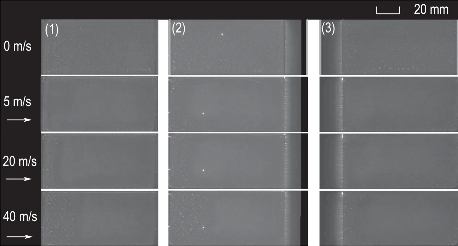
Figure 12.Top-view images of the discharges of different electrode structures under different airflow velocities.(1)Electrode geometry(a),(2) electrode geometry (b),(3) electrode geometry (c).The PRF is 1000 Hz,and the exposure time is 1/100 s.
3.4.Discharge state transition in airflow
Top-view images of the discharges of different electrode structures are shown in figure 12.The discharge gap is 4 mm,the PRF is 1000 Hz,and the exposure time is 1/100 s.The edge locations of the high-voltage and grounded electrodes are marked with red lines and green lines,respectively.The direction of the arrow indicates the direction of the airflow.From our previous works,it is known that the discharge state can be changed from a filamentary discharge to a diffuse discharge after introducing airflow [12,47].The generation of the diffuse discharge starts from the electrode edge at the airflow inlet due to the edge effect,which was observed in our previous experiment [12].Subsequently,the diffuse discharge at the electrode edge moves toward the downstream region under the action of the airflow.Meanwhile,airflow can also affect the distribution of the space charges.Ions with heavier mass leave in the volume,while electrons are accelerated by the external applied electric field and accumulate on the dielectric surface.This is because the drift velocity of electrons is larger than that of ions[9,48].Airflow first applies a drag force to the space ions because the airflow velocity in the boundary layer is almost zero,and the surface electrons move under the action of electrostatic coupling with the space ions [49].Therefore,the space charges in the upstream region move toward the downstream region,resulting in the decrease of the space charge density in the upstream region.Although the space charges in the downstream region also leave the region,it is supplemented by the space charges from the upstream region.The density remains basically unchanged.This has been reported in a previous work [50],which can verify that the PMT signal in the downstream region was earlier and stronger than that in the upstream region.Consequently,the diffuse discharge in the upstream region first transforms into a dense filamentary discharge,and the downstream region still manifests as a diffuse discharge.As the airflow increases further,the dense filamentary discharge extends continuously to the downstream region.The dense filamentary discharge is mainly ascribed to the relatively low space charge density.The lower space charge density is caused by the space charges moving toward the downstream region.Therefore,the length of the dense filamentary discharge in the upstream region can be regarded as the distance that the space charges move toward the downstream region within one discharge cycle.According to the formula u=L/t,where L is the length of the dense filamentary discharge region,and the time t is 1 ms.Tables 1 and 2 show the length of the dense filamentary discharge region and the moving velocity of the space charges for the different electrode structures,respectively.It can be seen that the moving velocity of the space charges is less than the corresponding airflow velocity.This phenomenon is consistent with our previous research using an alternatingvoltage source [49].This is mainly because the surface electrons need to overcome the shallow trap of the dielectric as well as the friction between the surface electrons and the dielectric plate.It is reasonable to believe that the reduction of the space charge density is the cause of the dense filamentary discharge.
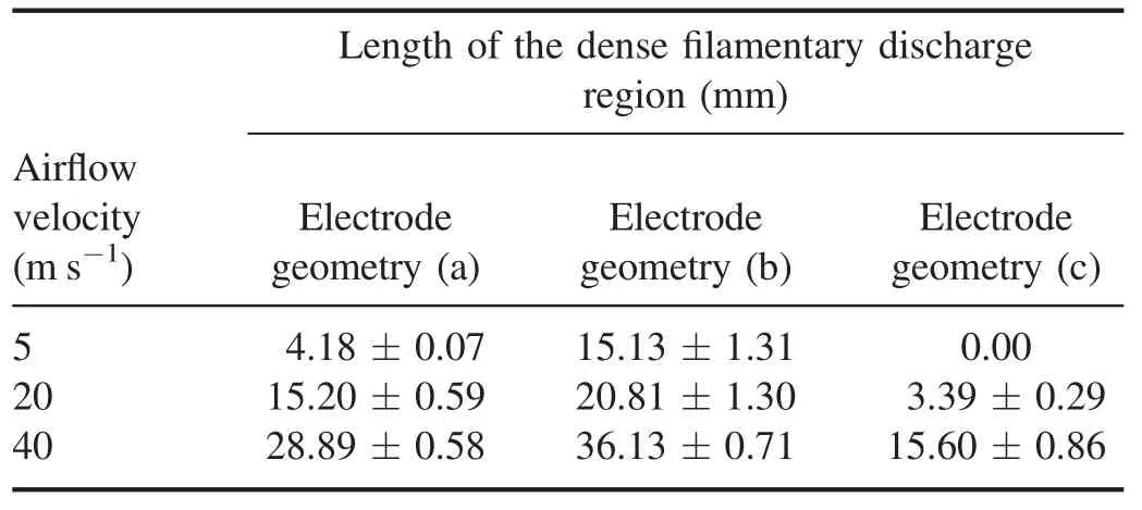
Table 1.Length of the dense filamentary discharge region for different electrode structures under different airflow velocities.
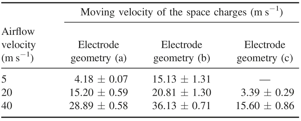
Table 2.Moving velocity of the space charges for different electrode structures under different airflow velocities.
As presented in figure 12,compared with the dense filamentary discharge region of the symmetric electrode geometry (a),the dense filamentary discharge region at the airflow inlet of the asymmetric electrode geometry (b) is larger.However,at a 5 m s-1airflow velocity,there is no dense filamentary discharge in the whole discharge space for the asymmetric electrode geometry (c),and the dense filamentary discharge region is smaller than that of symmetric electrode geometry.In other words,the electrode geometry(c)is conducive to improving the uniformity of the discharge.The effect of the transverse electric field on the movement of the space charges acts on the duration of the pulses,and the movement of the space charges induced by airflow occurs during the time interval of two consecutive pulses.When the airflow blows into the discharge gap in the same direction as the transverse electric field,the transverse electric field and the airflow cause the space charges to move in the same direction,which induces a larger displacement so that the space charges move toward the downstream region.The space charge density in the larger region is reduced,accordingly,and the dense filamentary discharge region at the airflow inlet is larger.However,for the asymmetric electrode geometry (c) the direction of the transverse electric field is opposite to the airflow,and the effect of the airflow on the movement of the space charges can be partly counteracted by the transverse electric field.The space charges do not easily move toward the downstream region,which results in the smaller dense filamentary discharge region at the airflow inlet.The above phenomenon can further illustrate the effect of the transverse electric field on the discharge by comparing the dense filamentary discharge region between the different electrode structures after introducing airflow.
4.Conclusions
The effects of the transverse electric field on a nanosecond pulsed DBD are studied in this paper.The discharge in the misaligned region is more diffuse than that in the central region for the asymmetric electrode geometry.The reason is that the space charges have transverse migration and are redistributed induced by the transverse electric field.Compared with the diffuse discharge at the edge for the symmetric electrode geometry,the diffuse discharge area is larger for the asymmetric electrode geometries.It can be explained that the micro-discharge channel is almost stationary due to the memory effect for the symmetric electrode geometry,however,the micro-discharge channel of asymmetric electrode geometries moves under the effect of the transverse electric field.In addition,the length of the diffuse discharge region along the direction of the transverse electric field increases with the decrease of discharge gaps and PRFs,which is consistent with the variation of the moving velocity of the micro-discharge channel.It is noted that the space charges can be uniformly distributed over a larger region under a faster moving velocity of the micro-discharge channel,which results in a larger area of diffuse discharge.
When the airflow is consistent with the transverse electric field of the asymmetric electrode geometry is introduced into the discharge gap,the area of the dense filamentary discharge at airflow inlet is larger than that of the symmetric electrode geometry.Nevertheless,the area of dense filamentary discharge is smaller for the asymmetric electrode geometry and the transverse electric field is opposite to the airflow.The main reason for the observed phenomena is the redistribution of the space charges by the movement of the micro-discharge channel due to the transverse electric field.
Acknowledgments
This work is supported by National Natural Science Foundation of China (No.51437002).The authors would like to thank Professor Zhenfeng Ding for his technical assistance in the use of the high speed motion analyzer.
猜你喜欢
动漫界·幼教365(小班)(2022年4期)2022-03-27
收藏与投资(2020年12期)2020-04-18
收藏与投资(2020年12期)2020-04-18
杂文选刊(2014年12期)2014-11-17
小天使·一年级语数英综合(2014年6期)2014-07-22
智慧与创想(2013年7期)2013-11-18
网球俱乐部(2009年9期)2009-07-16
数学大王·低年级(2009年5期)2009-05-31
数学大王·低年级(2009年5期)2009-05-31
数学大王·低年级(2009年5期)2009-05-31
 Plasma Science and Technology2020年5期
- Plasma Science and Technology的其它文章
- Investigation on the streamer propagation in atmospheric pressure helium plasma jet by the capacitive probe
- Numerical accuracy and convergence with EMC3-EIRENE
- Effects of trapped electrons on the ion temperature gradient mode in tokamak plasmas with hollow density profiles
- Contribution of joint experiments on small tokamaks in the framework of IAEA coordinated research projects to mainstream fusion research
- Underwater pulsed spark discharge influenced by the relative position between the top of a pin electrode and an insulating tube
- Investigation of the performance of CF3I/c-C4F8/N2 and CF3I/c-C4F8/CO2 gas mixtures from electron transport parameters