
A high performance waveform and a new ranging method for the proximity detector
2020-07-02 03:16QileChenXinhongHaoXiaopengYanPingLi
Defence Technology 2020年4期
Qi-le Chen, Xin-hong Hao, Xiao-peng Yan, Ping Li
School of Mechatronical Engineering, Beijing Institute of Technology, Beijing 100081, China
Keywords:Proximity detectors Detection performance Combination modulation Chaotic codes bi-phase modulation Linear frequency modulation
ABSTRACT Signal modulation is an essential design factor for proximity detectors and directly affects the system’s potential performance.In order to achieve the advantages of chaotic codes bi-phase modulation(CCBPM)and linear frequency modulation(LFM)simultaneously,this paper designed a waveform which combined chaotic codes bi-phase modulation and linear frequency modulation (CCBPM-LFM) for proximity detectors. The CCBPM-LFM waveform was analyzed in the aspect of time delay resolution (TDR) and Doppler tolerance (DT) based on ambiguity function (AF). Then, a ranging method, which we called instant correlation harmonic demodulation (ICHD), was presented for the detector using the CCBPM-LFM waveform. By combining time domain instant correlation with harmonic demodulation, the ICHD solved the problem caused by combination modulation and made the most of the linear frequency modulation(LFM)harmonics and the correlation of chaotic codes.Finally,a prototype was implemented and ranging experiments were carried out. From the theoretical analysis and experimental results, the proximity detector used the CCBPM-LFM waveform has an outstanding detection performance.
1. Introduction
Continuous wave proximity detectors constantly transmit and receive signals,so they are capable of maintaining a high signal-tonoise ratio with much less peak power than a corresponding pulse system [1]. For their simple structure, continuous wave radio proximity detectors are widely used in a plurality of areas,such as radio fuzes [2,3], radar altimeters [4], radar sensors [5] and so on.The radio fuzes play an important role in military and defensive,as they work in a complex electromagnetic environment, their detection performance,such as range resolution and anti-jamming performance, is vital and need to be focused on. There are a lot research on the detection performance of proximity detectors[6-8].As an essential design consideration for proximity detectors,the transmitting waveform directly affects the inherent performance of the system[9].
The United States radio fuze M734A1 and XXM733 use the FM proximity detector to get a high range resolution,but FM detectors suffer significantly by unintended interference and intended jamming [1]. With low-order modulation and low probability of interception (LPI), the bi-phase shift keying (BPSK) waveform has been adopted in detection systems[10-12].The ambiguity function(AF) [13] of the BPSK waveform is impulse, which means a good time delay resolution (TDR). Besides, the BPSK waveform has a unique advantage in anti-interference performance for its LPI. The TDR of a waveform is decided by its bandwidth,and the bandwidth of the BPSK waveform is the reciprocal of its code epoch[14,15].To get a higher TDR, a narrower code epoch is needed. However, it requires corresponding more power to conserve the integrated energy per code epoch, which is difficult for proximity detectors[16]. Another problem of the BPSK waveform is that it tends to exhibit high sensitivities to Doppler shifts with the code chip rate(the reciprocal of its code epoch)rising,which limits its application in high-speed moving targets[17].
The bandwidth of the transmitting waveform is a key factor of detection performance.Many researchers focus on achieving large bandwidth waveforms. In Ref. [17], the BPSK waveform was constructed by a group of phase sequences with a time varying partial code epoch.By varying the code epoch,the bandwidth is expanded.In addition, this waveform is not sensitive to Doppler shifts.However, additional hardware is needed for proximity detectors,and so extra cost is required for this method. A high-order binary offset carrier waveform provides a high range resolution without shortening the code epoch, so it does not increase the power consumption and Doppler sensitivities [9]. The large side-peaks of its autocorrelation function,however,may lead to false alarms.Hybrid modulation waveforms have also been investigated. In Ref. [18],two types of wideband hybrid-coding waveform, poly-phase discrete frequency waveform and poly-phase signed-chirp wave-6. Our conclusions are given in Section 7.
2. Mathematical models
The time domain model of the CCBPM-LFM signal as well as its spectrum are explored in this section.
2.1. Modulation principle
form, were proposed to obtain a wideband waveform for radar systems. The two hybrid-coding waveforms possess outstanding performance, but they lead to high-order harmonics. In Refs. [19,20], pseudo-noise BPSK and LFM were combined for transmission systems. By combining BPSK with LFM, the signal band is significantly expanded. Besides, this combination modulation is easy to be implemented.
Referring to the combined modulation of BPSK and LFM in transmission systems, this paper introduced a waveform which combined chaotic codes bi-phase modulation and linear frequency modulation(CCBPM-LFM)for proximity detectors.There are many appropriate sequences for BPSK, such as m sequences, M sequences,and Barker codes.Chaotic codes are generated from chaos,which is considered as a phenomenon of random behavior in certain nonlinear dynamic systems [21]. Chaotic codes have attracted attention in recent years for their randomness, initial sensitivity,good correlation,and quasi-orthogonal property[22,23,24]. All these characteristics make chaotic codes candidates for BPSK. By combining the chaotic codes bi-phase modulation(CCBPM)with LFM,the bandwidth of the transmitting waveform is highly expanded with less hardware cost. The performance of the CCBPM-LFM waveform was calculated based on the AF.Theoretical analysis showed that the CCBPM-LFM waveform has a high TDR and a good Doppler tolerance (DT). Besides, to extract the information of targets, a ranging method, which we called instant correlation harmonic demodulation (ICHD), was presented for the detector using the CCBPM-LFM waveform.By combining the time domain correlation with harmonic demodulation,the ICHD solved the problem caused by combination modulation and made the most of the LFM harmonics and the correlation of chaotic codes.Finally, a prototype was implemented and some ranging experiments were completed. The results showed that the detector designed in this paper achieved outstanding detection performance.The main contributions of this paper are as follows:(1)this paper designed a CCBPM-LFM waveform for proximity detectors which achieved the advantages of LFM and CCBPM;(2)the TDR and DT of the CCBPM-LFM waveform was analyzed based on AF; (3) a new ranging method combining time domain instant correlation with harmonic demodulation was designed for the detector using CCBPM-LFM waveform; (4) a prototype was implemented.
The rest of the paper is organized as follows: the time domain model of the CCBPM-LFM waveform and its spectrum are introduced in Section 2. Section 3 gives a detailed analysis of the CCBPM-LFM waveform based on its AF.In Section 4,we reveal the ICHD ranging principle. Section 5 provides numerical simulation.The prototype and the experimental results are described in Section
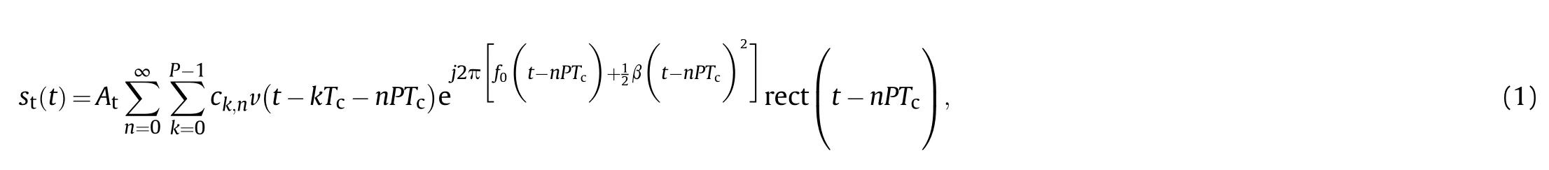
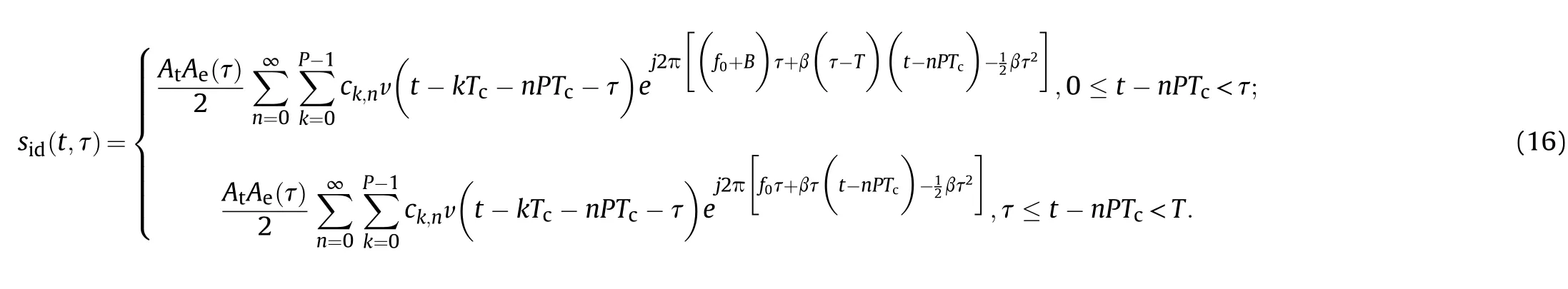
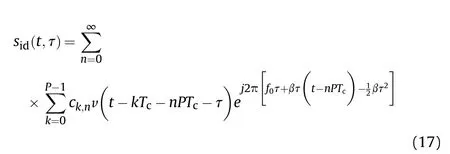
Taking up-ramp LFM as an example,the CCBPM-LFM signal can be expressed mathematically in the following equation
where {ck,n=±1} are the chaotic codes, ck,nis the kth element of the nth sequence, Tcis the chip epoch, P is the length of each sequence,f0is the carrier frequency,B is the LFM bandwidth,is the LFM slope,is the modulation frequency of LFM,Atis the amplitude of the transmitting signal,is a gate function with the duration of Tc, andis also a gate function with the duration of PTc. The waveform of the CCBPM-LFM signal is illustrated in Fig.1.
2.2. The spectrum of the CCBPM-LFM signal
Noting un(t)as the complex envelope of the nth segment of the CCBPM-LFM signal,normalizing the amplitude to unity,un(t),can be expressed as
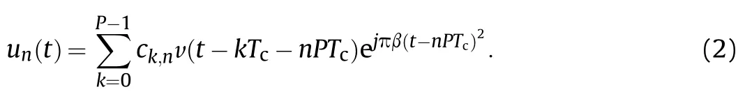
Using F{·} to represent the Fourier transform operator, it is obvious that the spectrum of un(t) is as follow
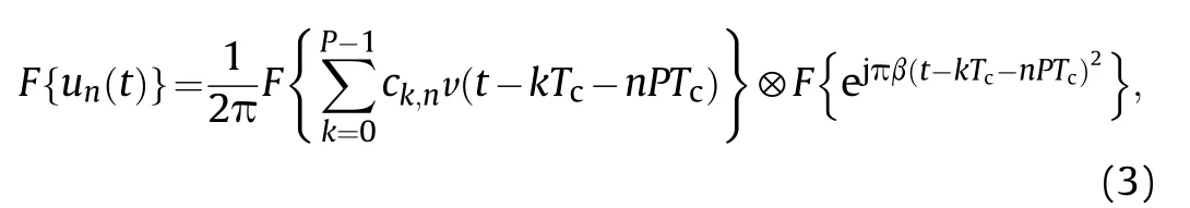
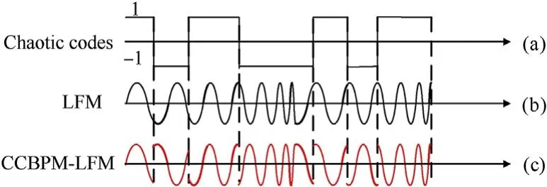
Fig.1. Illustration of the waveform of (a) the chaotic codes, (b) the linear frequency modulation (LFM) signal, and (c) the chaotic codes bi-phase modulation and linear frequency modulation (CCBPM-LFM) signal.
From Eq.(3),different from the CCBPM waveform,the spectrum of the CCBPM-LFM signal is the convolution of LFM and CCBPM.The bandwidth of CCBPM is decided on its chip epoch;A narrower chip epoch is needed to get a larger bandwidth,which is difficult for the proximity detectors. However, the bandwidth of CCBPM-LFM is decided by the chip epoch and LFM bandwidth jointly, so its bandwidth can be expanded by just increasing the LFM bandwidth.
3. Performance analysis of the CCBPM-LFM waveform
On the basis of AF, the TDR and Doppler tolerance (DT) of the CCBPM-LFM are analyzed in this section.
3.1. Ambiguity function
The AF is an effective tool for waveform design and analysis.It is only determined by the transmitting waveform and can reflect the detection performance of the system.According to the definition of AF[12],the auto-ambiguity function of the CCBPM-LFM signal can be expressed as

where χa(τ,fd) is the AF of the CCBPM signal, which can be represented as (the detailed derivation is shown in Appendix A)
where j = 0,1,2…P- 1; j and τ always satisfy the equation |τ -
jTc|<Tc. From Eq. (5) and Eq. (6) we can obtain χA(τ,fd) as

3.2. Time delay resolution of the CCBPM-LFM signal
The AF of the CCBPM-LFM signal seems to be complex. However, with fd= 0, χA(τ,fd) degrades into the range ambiguity function (RAF)

It is noteworthy that there are no standard parameters for TDR-a widely accepted definition is 3 dB width of the main lobe of the range ambiguity function, which is recorded as τs. To have a good TDR,the detector needs a smaller τs.It is certain that the range ambiguity function appears at the main lobe when j = 0, and τssatisfies
The left side of Eq.(9)is nonlinear,but it can be approximated as a linear function. Therefore, we can obtain τsby figuring out τ0which matches the following equation
From Eq.(11),we know that the TDR of the CCBPM-LFM signal is affected by the LFM bandwidth and the reciprocal of the chaotic codes chip epoch(code chip rate)jointly.Under this condition that LFM bandwidth is larger than the code chip rate,it is determined by LFM bandwidth; otherwise it is determined by the chaotic codes rate. As a narrower chaotic codes chip epoch is easy to obtain, we can improve the TDR by increasing the LFM bandwidth.
3.3. Doppler tolerance of the CCBPM-LFM waveform
Relative motion between targets and detectors causes a Doppler effect, which decreases the main lobe of the AF. Obviously, the Doppler Effect is not conducive to target detection. The DT is used to measure the detector’s tolerance of Doppler Effect. It can be evaluated by the maximum Doppler shift, with which the main lobe of the AF decrease to zero. The main lobe of the AF, which is derived from Eq. (7), with j=0 and |τ|<Tc, can be expressed as
When the main lobe decreases to zero,the Doppler shift satisfies

From Eqs. (12) and (13), the addition of LFM leads to a rangevelocity coupling of the CCBPM-LFM waveform, which relieves the decrease of the main lobe. As |τ|<Tc, we can calculate the Doppler tolerance as
From Eq. (14), the DT of the CCBPM-LFM waveform is decided by the LFM bandwidth and the chip epoch collectively.Therefore,a large LFM bandwidth not only improves the TDR but also relieves the decrease of the main lobe resulting from the Doppler shift.3.4. The LPI of the CCBPM-LFM waveform
Employing interception factor [24] to measure the LPI of the CCBPM-LFM waveform, The smaller interception factor, the better anti-jamming performance. The formula of the interception factor is as follow

where K is decided by the receiver of the radar or jammer, Teis effective time duration,Beis effective bandwidth.The spectrum of the CCBPM-LFM signal is the convolution of LFM and CCBPM.With the same time duration,the effective bandwidth of the CCBPM-LFM is wider than the CCBPM signal. The interception factor of the CCBPM-LFM is better than the CCBPM.
4. The ICHD ranging principle
The CCBPM-LFM waveform uses CCBPM and LFM jointly,which lead to a cross-modulation problem. Limited by the simple structure and small size, the proximity detector is unable to process radio frequency signal. So after receiving target echo signal, the detector mixes it with the local reference signal(LRS)to obtain the beat signal. The beat signal is a product of chaotic codes and LFM beat signal, its spectrum is disorderly and expanded. Neither the traditional correlation ranging algorithm nor the harmonic demodulation ranging method can extract the range information of targets. Here we propose a ranging method, the ICHD ranging method, which combines time domain instant correlation with harmonic demodulation.
The block diagram of the detector implemented with the ICHD is shown in Fig.2.The detector transmits the CCBPM-LFM signal and mixes the target echo signal with the local reference signal(LRS)to obtain the beat signal.After sampling,the beat signal is sent to the ICHD block. Firstly, the beat signal multiplies a delayed replica of chaotic codes to realize instant correlation.Then,a band pass filter(BPF)is used to obtain a certain harmonic of the beat signal.Finally,maxing the harmonic with a reference signal from direct digital synthesizer(DDS), Doppler signal can be obtained. We can get the range information and velocity information from the Doppler signal.
The echo signal is an attenuated and delay version of the transmitting signal,which can be expressed as sr(t,τ) =Ae(τ)st(t -τ), where Ae(τ) is the attenuation factor changing with the time delay,and τ the round-trip time for the signal to propagate from the detector and back. For a specified target with a velocity v0, and initial distance R, the time delay of the target echo signal can be expressed as τ =, and c=3×10⁸m/s is the speed of the electromagnetic wave. It should be noted that the local reference signal is LFM signal generated by the voltage-controlled oscillator(VCO).
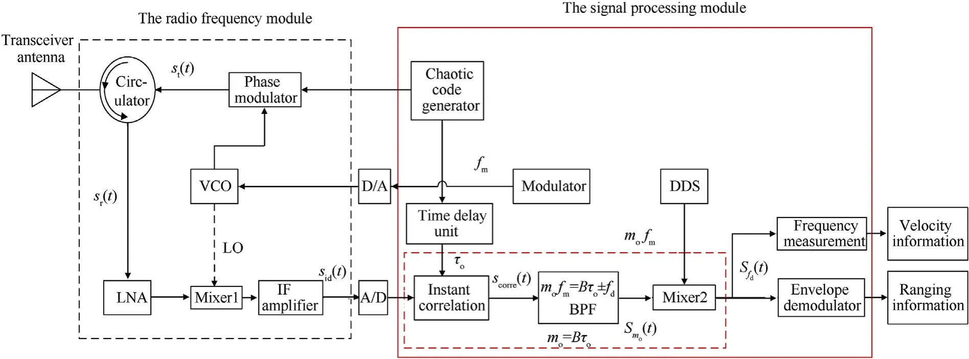
Fig. 2. Block diagram of the detector implemented with correlation band pass filtering (ICHD). LNA: low-noise amplifier; VCO: voltage-controlled oscillator; LRS: local reference signal; DDS: direct digital synthesizer; BPF: band pass filter.
Maxing the target echo signal with the local reference signal,the beat signal can be expressed as
In general, the detection range of the proximity detectors is short which means τ·PTc,so the beat signal during 0 ≤t-nPTc<τ can be ignored. Besides, the amplitude of the reflected signal has little impact on the performance of the detectors. In order to simplify the analysis, we can normalize the amplitude of the beat signal.After the amplitude has been normalized,the beat signal can be simplified as
After sampling, the beat signal is sent to the signal processing system and the ICHD is used to obtain the information of the target.The ICHD combines the time domain correlation with harmonic demodulation. It is implemented in two steps:
(1) If the predetermined range of the detector is Ro, the beat signal is firstly multiplied with a replica of chaotic codes which is delayed by τo=. Defining tn= (t - nPTc), the signal obtained in the first step can be expressed as
(2) Then, scorre(tn,τ) is allowed to pass through a BPF to get theharmonic, where mosatisfies that mo= Bτo. The spectrum of scorre(tn,τ) is as follow
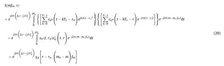
In general, the target speed is v0<<c, so τ can be considered constant during the PT0time interval,which means S(mfm,τ)can be simplified as With Eq. (20), we can calculate that the envelope of the mth harmonic is the cross section of the ambiguity function along the τ axis at the position of (mo- m)fm. After the BPF, the mothharmonic of scorre(tn,τ) can be expressed as
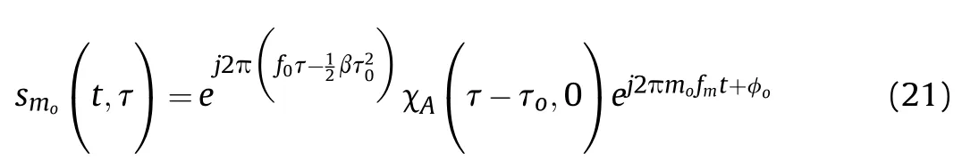
With the motivation of the target, the Doppler information is also carried on smo(t,τ).Mixing it with the signal generated by the DDS with the frequency mofm, the Doppler signal can be obtained as
The Doppler signal inherits the envelope of smo(t,τ). When the target is close to the detector, the amplitude of fd(t,τ) gradually reaches the main lobe.Therefore,we can get the range information with a threshold.Besides,we can get the velocity information of the target by measuring the frequency of the Doppler signal, and the speed of the target isSetting 3 dB width of the main lobe of the Doppler signal as the threshold, the range resolution of the detector is as
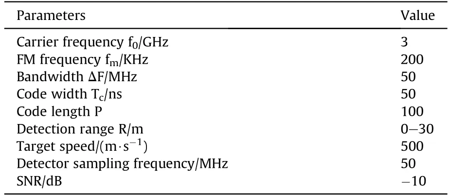
Table 1 Simulation parameters.
Changing the time delay τoas well as the corresponding harmonic,the detector can control the predetermined range.From Eqs.(23) and (12), the range resolution of the detector implemented with ICHD is only decided by the TDR of the CCBPM-LFM waveform.
5. Simulation and discussion
In this section, we simulate and discuss the detection performance of the CCBPM-LFM waveform, as well as the ICHD ranging method. The simulation parameters are set as Table 1.
5.1. Simulation and analysis of the CCBPM-LFM signal
With the same code epoch, the spectrum of the CCBPM and CCBPM-LFM waveform are shown in Fig. 3. The spectrum of the CCBPM is shown in Fig. 3(a), as the code epoch is 50 ns, the bandwidth of the CCBPM is about 20 MHz. The spectrum of the CCBPM-LFM, shown in Fig. 3(b), is significantly affected by the combination with LFM.It retains the noise-like characteristic of the CCBPM while having a wider bandwidth.
The bandwidth is about 30 MHz when the LFM bandwidth is 10 MHz, and about 70 MHz when the LFM bandwidth is 50 MHz.Namely, the bandwidth of the CCBPM-LFM is expanded significantly with a larger LFM bandwidth B.From the simulation results,the bandwidth of the CCBPM-LFM can be approximated as.With the same effective time duration Te= PTc, the interception factor of the CCBPM isand the interception factor of the CCBPM-LFM is.Compared with the CCBPM waveform,the CCBPM-LFM waveform has a wider bandwidth and a lower interception factor.
The ambiguity surface of the CCBPM-LFM waveform,shown in Fig.4(a),is obviously impulsive which means a good TDR.Besides,compared with the CCBPM waveform shown in Fig. 4(b), the ambiguity surface of the CCBPM-LFM rotates in the τ-fdplane which results in a lower side lobe.The rotation angle is related to the LFM slope. The range ambiguity function of the CCBPM-LFM and the CCBPM are shown in Fig. 5. The TDR is only decided by the main lobe of the range ambiguity function. As shown in Fig. 5, with the LFM bandwidth about 50 MHz,the main lobe of the CCBPM-LFM is narrower than the CCBPM’s, so its TDR is better than that of the CCBPM.
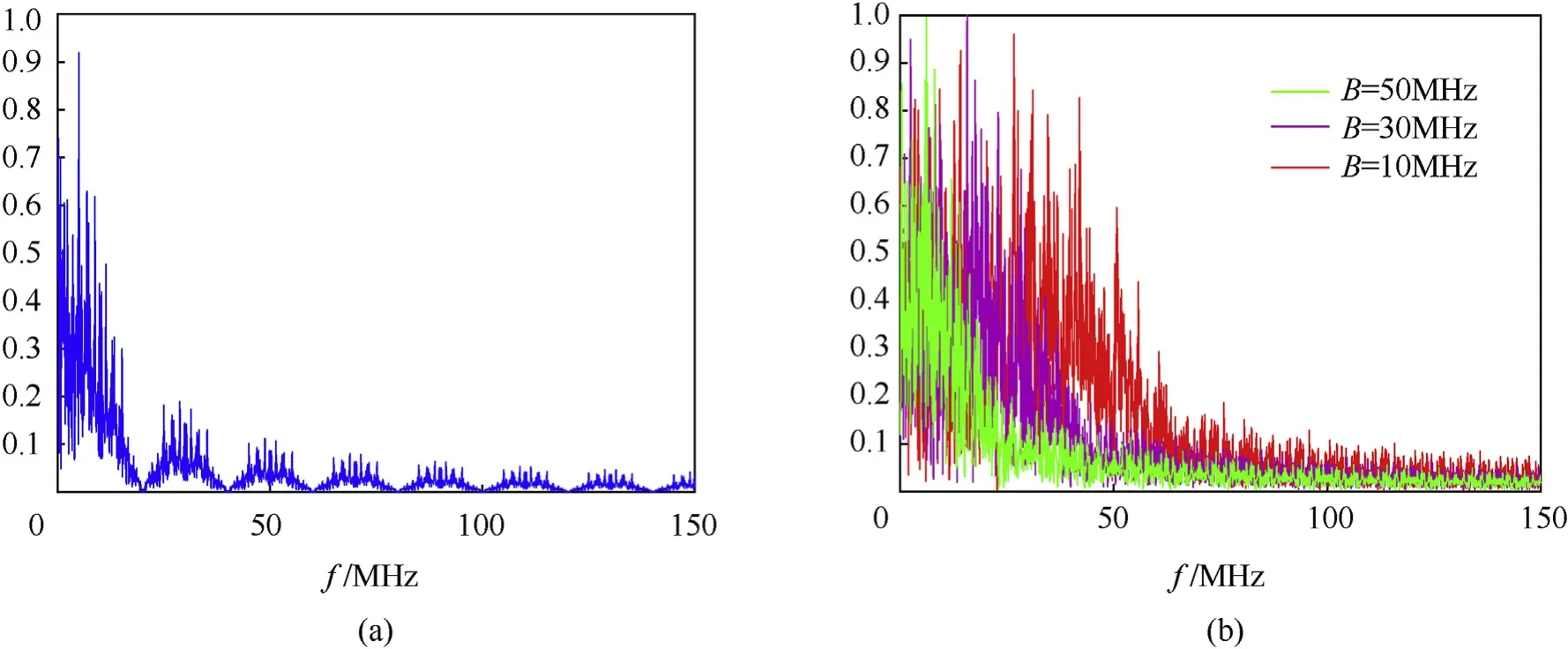
Fig. 3. The spectrum of (a) the CCBPM waveform; (b) the CCBPM-LFM waveform with different LFM bandwidth (B).

Fig. 4. The ambiguity surface of (a) the CCBPM-LFM signal and (b) the CCBPM signal.
Fig. 5. The range ambiguity function of the CCBPM-LFM and the CCBPM.
A detailed description of τschanging along with the LFM bandwidth and code epoch is shown in Fig.6.Fig.6(a)describes the surface that τschanges along with the LFM bandwidth and the code epoch.It shows that a large LFM bandwidth or a narrow code epoch means a small τs. Fig. 6(b) gives a more detailed relationship between τsand the LFM bandwidth. τsdecreases with LFM bandwidth increasing.It can be concluded τsis inversely proportional to the LFM bandwidth. When the LFM bandwidth is small, τsis significantly affected by the code epoch.Fig.6(c)gives a curve of the τsand code epoch. τsincreases with the code epoch rising when the LFM bandwidth is constant.It is proportional to the code epoch with the LFM bandwidth being zero.But when the LFM bandwidth is not zero, the τswill be constant after the code epoch is greater than a critical value.
From the top view of the ambiguity surface, shown in Fig. 7(a),we can see that the projection of the CCBPM-LFM on the τ-fdplane is elliptical with a rotation angle compared with the CCBPM waveform. It is obvious that the rotation improves the Doppler tolerance. With the LFM bandwidth ΔF = 50 MHz, the fdmaxof the CCBPM-LFM waveform is 0.33 MHz contrasting with 0.15 MHz of the CCBPM waveform.These are not perfectly matched with Eq.(14)for the section we select here is about z=0.3,not z=0,to avoid the side lobe effect. Fig. 7(b) gives a description of the surface,showing that the Doppler tolerance changes along with the LFM bandwidth and code epoch. Fig. 7(c) shows that the Doppler tolerance is proportional to the LFM bandwidth with the same code epoch. Fig. 7(d) describes that the Doppler tolerance is inversely proportional to the code epoch. From the analysis, it can be deduced that the Doppler tolerance can be improved by a wider LFM bandwidth or a narrower code epoch.
5.2. The ICHD ranging principle

Fig. 6. The influencing factors of TDR: (a) the relationship between TDR, LFM bandwidth and code epoch, (b) the relationship between TDR and LFM bandwidth, and (c) the relationship between TDR and code epoch.
Fig.7. Doppler tolerance of the CCBPM-LFM:(a)the top view of the ambiguity surface,(b)the relationship between the Doppler tolerance,the LFM bandwidth and the code epoch,(c) the relationship between the Doppler tolerance and the LFM bandwidth, and (d) the relationship between the Doppler tolerance and the code epoch.
As proximity detectors work under the condition of a low signal to noise ratio (SNR), the background noise of additive white Gaussian noise is added in the simulation with the SNR equaling to-10 dB.The predetermined range we choose here is 15 m,which corresponds to mo= 5. To understand the ICHD better, it is necessary to give a discussion of the beat signal. In Fig. 8(a), we show a time section of the beat signal.The combination modulation of LFM and CCBPM causes the beat signal of the detector a product of chaotic codes and LFM beat signal. Therefore, its spectrum is disorderly and expanded shown in Fig. 8(b). If the detector uses traditional correlation ranging algorithm (Fig. 9(a)) to extract the range information of the target, as the LFM beat signal is much higher than, it cannot achieve correlation peak of the chaotic codes. The output of the detector shown in Fig. 9(b) is flat in any time,and the detector cannot obtain the information of the target.
To solve the correlation peak deterioration caused by LFM beat signal, the ICHD introduces harmonic demodulation before integration.It is specifically implemented in two steps.The first step is instant correlation. This step is mainly to sustain the correlation characteristic of the chaotic codes. After instant correlation, the energy of the beat signal is aggregated. Fig. 10(a) shows a time section of the scorre(t), different from sid(t) shown in Fig. 8(a), the scorre(t) becomes a LFM beat signal when the target near the predetermined range. The spectrum of the scorre(t) is shown in Fig.10(b).The energy of the scorre(t)is mainly concentrated on the fifth harmonic. Therefore, we can get the range information by extracting the fifth harmonic after instant correlation.
Fig. 8. The beat signal of the detector in (a) time domain and (b) frequency domain.
Fig. 9. Traditional correlation ranging algorithm: (a) the block diagram, (b) the output of the detector.
After instant correlation, the ICHD realizes harmonic demodulation by a BPF.The fifth harmonic obtained by the BPF is showed in Fig.11(a).The fifth harmonic appears peak at 14.63 m,and its main lobe width is about 6 m. Mixing the fifth harmonic with the reference signal from DDS, the Doppler signal can be obtained. The Doppler signal,shown in Fig.11(b),has the same envelope with the fifth harmonic, namely it carries the range information of the target.The detector can obtain the range information of the target by measuring amplitude of Doppler signal. Setting 3 dB width of the main lobe as a threshold,the range resolution of the detector is about 3 m. Also, the velocity information can be calculated by measuring the frequency of the Doppler signal,and the speed of the target v0satisfies that
Fig.10. The signal after instant correlation in: (a) time domain and (b) frequency domain.
Fig.11. Time domain waveform of (a) the fifth harmonic; (b) the Doppler signal.
Fig.12. The designed prototype: (a) the radio frequency module, and (b) the FPGA system.

Fig.13. The scenery of the ranging experiments.
6. Ranging experiments
In this section, the prototype is introduced and the ranging experiments are explained.The prototype is designed based on the structure described in Fig.2.Images of the prototype is provided in Fig.12,the radio frequency module is provided in Fig.12(a),and the signal processing system completed by the field programmable gate array(FPGA)XC3S1000 hardware is provided in Fig.12(b).The parameters of the prototype are same as Table 1, and the ranging performance of the prototype was tested in the scene shown in Fig.13. The prototype is placed on a desk at the end of the track,which was about 30 m long.The target fixed on the handbarrow is a metal plate with a radar cross section (RCS) of 1 m2which approached the prototype at a speed of 3 m/s.
Fig.14. The output of the prototype.
The output of the prototype is shown in Fig. 14. The Doppler signal of the prototype appears main lobe during the approach of the target. Its envelope occurs peak, with the width about 6 m,when the target is at about 15 m from the prototype.
A jammer with power 30 dBm is put opposite the prototype,and we test the performance of the prototype under jamming. The output of the prototype under sweep jamming is shown in Fig.15.Fig.15(a)is the output without targets;the output of the prototype is flat. Fig.15(b) is the output with a target approaching the prototype.The prototype works well under the sweep jamming.From the results, the prototype has a good anti-jamming performance.
7. Conclusion
To improve the detection performance of the continuous wave proximity detectors, this paper designed the CCBPM-LFM waveform which combined CCBPM with LFM, and introduced the ICHD ranging method. Based on the AF, the TDR and DT of the CCBPM-LFM waveform were analyzed. The TDR and DT are decided by the LFM bandwidth and chaotic codes chip epoch,collectively. They can be highly improved by increasing the LFM bandwidth of the CCBPM-LFM waveform.The ICHD combines the instant correlation with harmonic demodulation, and it solves the problem caused by combination modulation effectively.With BTc>1,the range resolution of the detector designed in this paper isBesides,with LPI,the anti-jamming performance of the detector is also good.
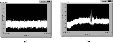
Fig.15. The output under sweep jamming (a) without targets and (b) with a target.
Declaration of competing interest
The authors declare no conflict of interest.
Acknowledgments
This work is supported by the State Key Program of Basic Research of China under Grant No.613196 and the National Natural Science Foundation of China under Grant No.61673066.

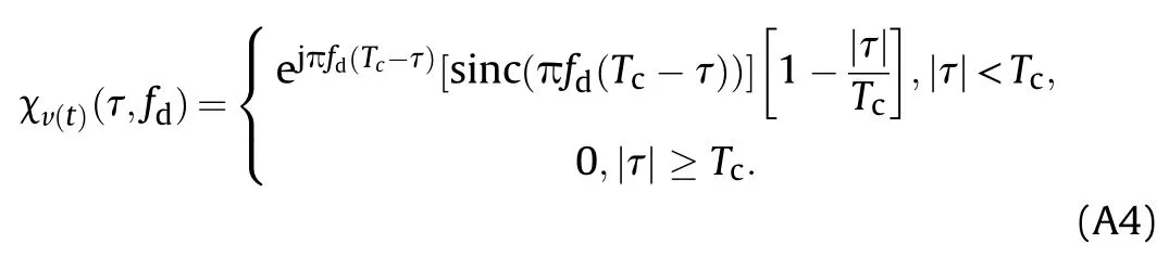
where χv(t)(τ,fd) represents the AF of v(t) and χuc(τ,fd) represents the AF of uc(t). According the definition of AF, χv(t)(τ,fd) and χuc(τ,fd) can be figured out as follows

Appendix A
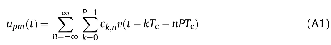
With the chip epoch, Tc, and sequence length, P, the CCBPM signal can be expressed as
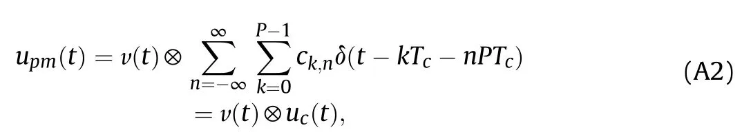
According to the property of convolution operation, upm(t) can be decomposed as
The AF of the CCBPM signal can be derived from
Finally, we get the AF of the CCBPM signal:
- Defence Technology的其它文章
- Analysis of sliding electric contact characteristics in augmented railgun based on the combination of contact resistance and sliding friction coefficient
- Aerodynamics analysis of a hypersonic electromagnetic gun launched projectile
- Synergistic effect of hybrid Himalayan Nettle/Bauhinia-vahlii fibers on physico-mechanical and sliding wear properties of epoxy composites
- Study on dynamic response of multi-degree-of-freedom explosion vessel system under impact load
- An investigation on anti-impact and penetration performance of basalt fiber composites with different weave and lay-up modes
- Modeling and simulation of muzzle flow field of railgun with metal vapor and arc