
Accident Analysis and Emergency Response Effect Research of the Deep Foundation Pit in Taiyuan Metro
2020-09-23 02:39ZHANGXiaoshuang张晓双FENGChaoHANYunshan韩云山ZHANGJun
关键词:云山
ZHANG Xiaoshuang(张晓双),FENG Chao(封 超), HAN Yunshan(韩云山),ZHANG Jun(张 军)
1 School of Science,North University of China,Taiyuan 030051,China2 Key Laboratory of Highway Construction and Maintenance Technology in Loess Region,Shanxi Trasnsportaion Research Institue,Taiyuan 030006,China
Abstract: Taking the deep foundation pit accident occurring at a station of metro Line 2 in Taiyuan as an example,the influence of the seepage and inrush of the foundation pit on the retaining structure and surrounding environment were studied under the geological conditions of the confined aquifer on the east coast of Fenhe River. The causes of deep foundation pit accident were also analyzed systematically based on the monitoring data,and various emergency measures were proposed to control the occurrence of secondary accident for deep foundation pit. The results showed that the occurrence of inrush for foundation pit was mainly caused by the insufficient dewatering. The development of the accident was effectively controlled by the adding of the dewatering wells,local grouting of retaining structure to stop seepage,surface grouting to reinforcement and uplift soil. The successful experience can provide some guidance to the construction of similar projects in the proposal.
Key words: metro station; deep foundation pit; inrush; seepage; grouting reinforcement
Introduction
With the rapid development of national urban construction,deep foundation pits of urban metro keeps emerging. At present,most underground engineering problems are closely related to groundwater characteristics. The water head difference between the inside and outside of a foundation pit would induce seepage in the high ground water table,which had significant influence on excavation engineering. In order to prevent engineering accidents caused by underground water,such as water inrush,quicksand,piping,land subsidence,collapse,building cracks,broken pipes,and failure of the retaining structure,it is necessary to pay attention to the problem of underground water and formulate the solution measures in time.
Aiming at the groundwater problem in foundation pit engineering,the researchers used a variety of methods to conduct the study,such as model test[1],numerical modeling[2-3]and case analysis[4]. The lowering of the groundwater level outside the pit can lead to ground subsidence,affecting the stability of surrounding buildings[5-6]. The effect of the pre-excavation dewatering on the retaining walls and soil in the foundation pit was deeply studied,indicating that time effect and size effect were two features of dewatering-induced deformation[7-8]. In order to minimize dewatering-induced ground settlements in deep excavation,the artificial recharge method is adopted,which can compensate the drawdown by injecting the water into the aquifer[9-10]. Zengetal.[11-13]proposed a method referred to as the combined recharge concluding the artificial recharge wells and traditional recharge wells,and response of deep soils during combined recharge and the influence of opening timing of recharge wells on settlement were also studied. However,the insufficient of dewatering groundwater level can also lead to the happen of accident. Hence,the drawdown of the groundwater outside the foundation pit must be strictly controlled. A 32.55 m deep circular foundation pit was selected as an example to study the dewatering scheme under potential leakage conditions[14]. Field experiments and numerical simulations were performed to determine potential leakage risks,and water inrush and piping were successfully controlled by pre-installed pumping wells. Considering the different hydrogeological conditions of each area of the foundation pit near the Yangtze River,a 3D numerical simulation was adopted to evaluate the effect of the dewatering schemes,and the optimal dewatering scheme was proposed according to the simulation results[15]. In addition,the stability calculation method of foundation pit inrush was also studied[16-17].
A certain thickness of silt sand and middle sand with good permeability exist in the soil of Taiyuan. Under the strong permeation of groundwater,soil particles are easy to move and lose in the formed pore channel,and the permeation volume also increases sharply,which increases the difficulty of excavation and precipitation. The inrush induced by permeation occurs easily,resulting in the gushing of water and sand,the damage of foundation pit and the collapse of ground surface.
This study focuses on the influence of the inrush and seepage on retaining structure and surrounding environment based on a foundation pit accident of Taiyuan metro Line 2 station. The reasons of the accident are also analyzed and a variety of emergency measures are proposed to prevent the occurrence of secondary disasters. This case provides certain guidance for other similar metro foundation pits.
1 Background Introduction of the Case
The station is located in the outskirts of Taiyuan,which is close to the farmland in the northwest side and the old shooting range in the northeast side,as shown in Fig. 1. The total length,width and excavation depth of the station are 307.550,21.600 and 19.042 m,respectively,among which the width of the north end side is 25.7 m specially. The station of “island-style,double-storey,double-pillar and three-span” box frame structure is constructed by means of open-cut excavation method. The soil mechanical parameters of north end side can be seen in Table 1.
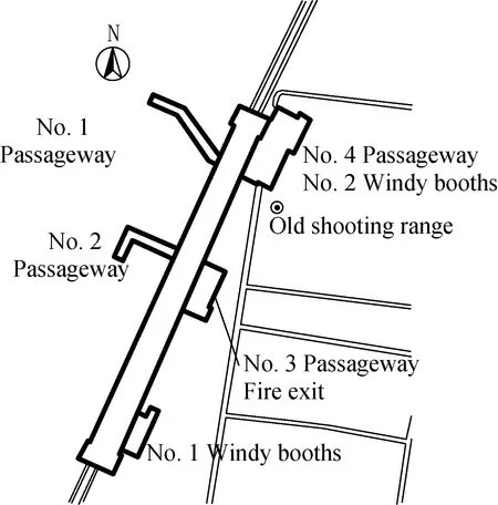
Fig. 1 Station layout plan
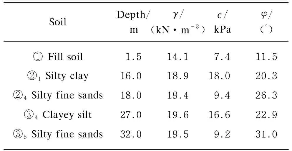
Table 1 Soil mechanical parameters
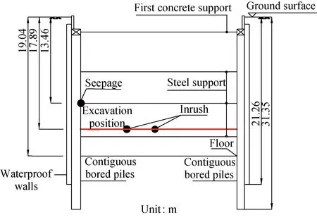
The groundwater at the station site is located in phreatic aquifers or micro-confined aquifers. The micro-confined aquifer mainly exists in ③5silty fine sands (shown in Fig. 2). The groundwater level of phreatic aquifer is 1.6-4.3 m below the ground surface,and the fluctuation of level is general ±(1-2) m. The phreatic aquifer is susceptible to atmospheric precipitation and human activities due to its shallow location and small flow.
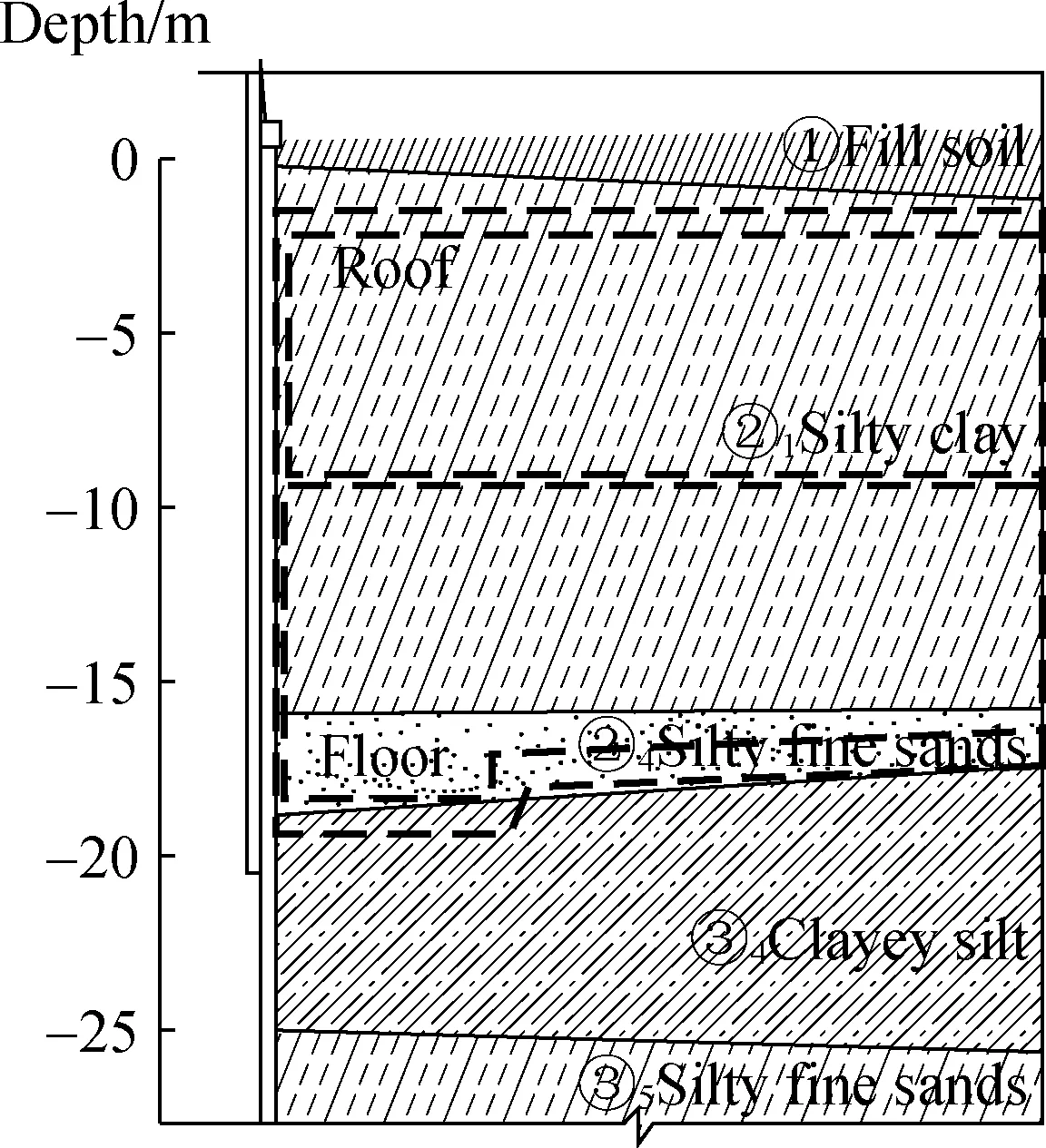
Fig. 2 Geological section of north end side of foundation pit

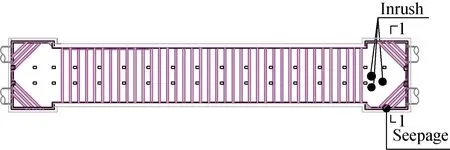
(a) Foundation pit supporting plan
(b) Supporting layout of seepage point of foundation pit
2 Overview and Impact of the Foundation Pit Accident
2.1 Overview of the foundation pit accident
At 9∶00 a.m. on March 31,2017,as shown in Fig. 3,the third support at the north end side had been installed,and the excavation depth was about 17.89 m,which was only 0.57 m away from the fourth support. Suddenly,large amount of water mixing with soil seeped from the waterproof wall,which was slightly above the position of the third support [S1,shown in Fig. 3 and Fig. 4(a)]. At the same time,two inrush points located at the excavation surface of north end side begun to pour water with small flow rate [T1 and T2,shown in Fig. 4(b)]. At 12∶00 a.m. on April 1,the diameter of the seepage point expanded significantly,resulting in the increasing of the soil loss. For the inrush points,the water flow of the T1 and T2 increased gradually and the third inrush point appeared,indicating the engineering risks rose step by step. By 3∶00 p.m. on April 1,the water accumulation induced by the inrush in the foundation pit had become very serious,as shown in Fig. 5.
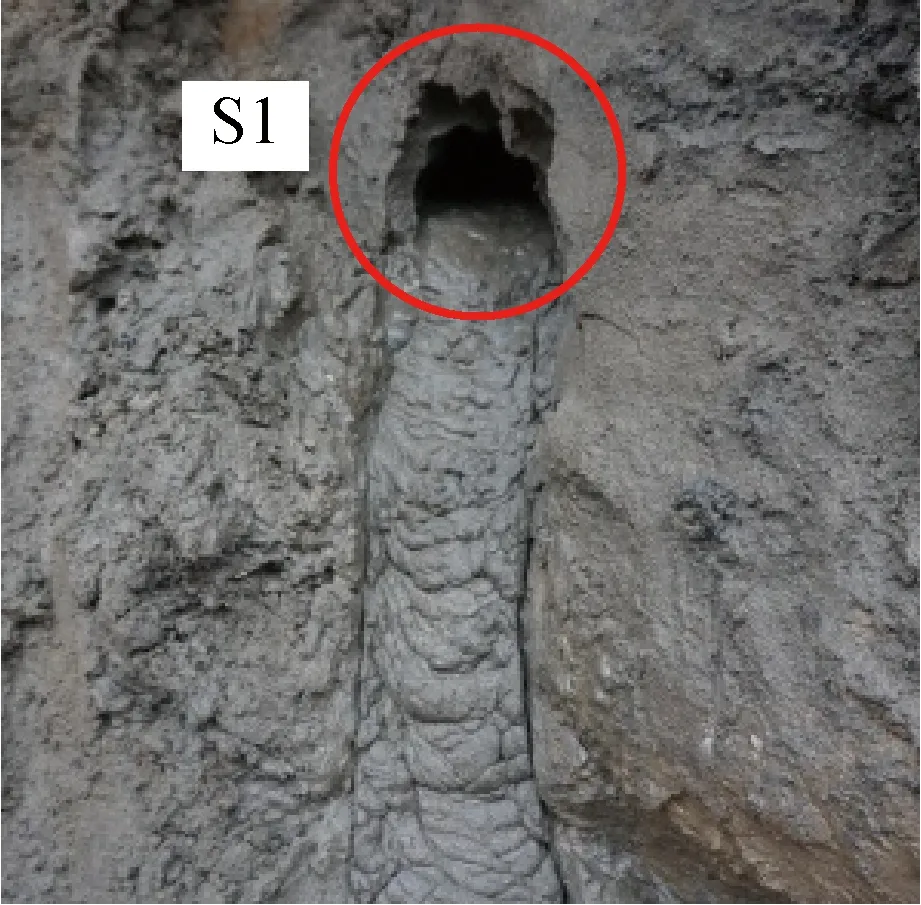
(a) Seepage point

Fig. 5 Water accumulation in foundation pit
2.2 Impact of the foundation pit accident
2.2.1Settlementofthegroundsurface
Field monitoring data analysis is an important measure to ensure the safety of deep foundation pit and surrounding environment. The layout of monitoring points on the north end side of foundation pit is shown in Fig. 6,which mainly contains the displacement of ground surface,horizontal displacement on the top of wall and observation well.

Fig. 6 Plane view of the instrumentation layout on the north end side of foundation pit
The displacement of ground surface around the foundation pit is shown in Fig. 7.
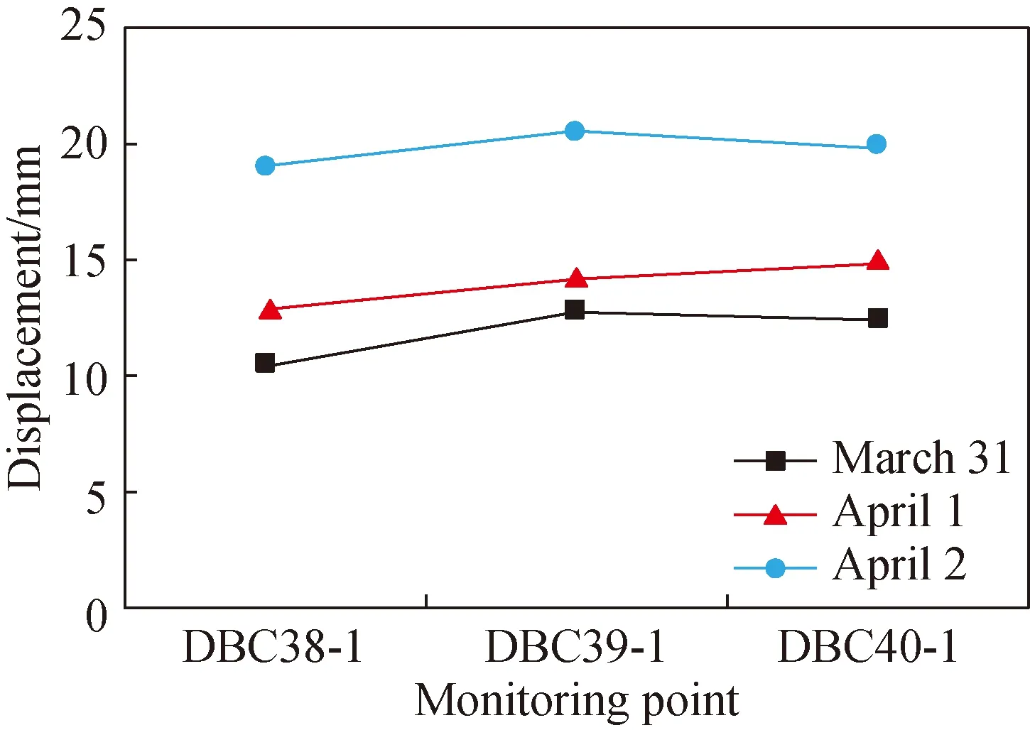
(a) Monitoring points adjacent to the foundation pit
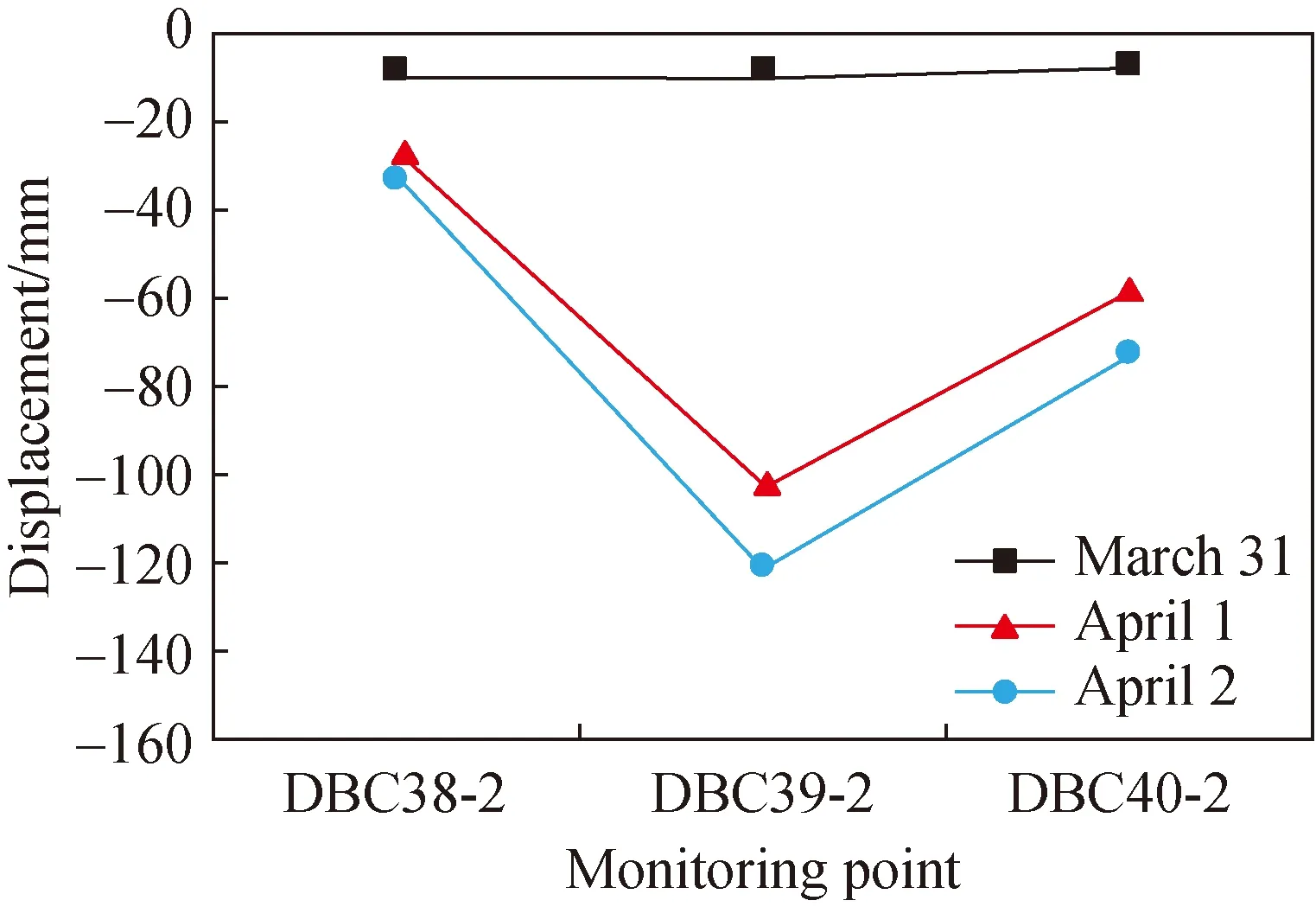
(b) Monitoring points away from the foundation pit
The displacement of the monitoring points of DBC38-1,DBC39-1 and DBC40-1 adjacent to the foundation pit occurred a certain degree of uplift,and the differences between the values were small when the monitoring time was the same. For the same monitoring point,the variation rate increased significantly from about 2 mm/d on April 1 to about 6 mm/d on April 2,which exceeded the warning value of 3 mm/d. By contrast,the displacement of the monitoring points of DBC38-2,DBC39-2 and DBC40-2 away from the foundation pit showed a certain degree of settlement. On March 31,the settlement of the monitoring points of DBC38-2,DBC39-2 and DBC40-2 was small,but the settlement rose significantly on April 1 and the increment of settlement was significant larger when the monitoring point was closer to the seepage location. Specifically,the value and variation rate of settlement for DBC39-2 reached up to 102.7 mm and 92.4 mm/d,respectively,which both vastly exceeded the warning values. The gushing of water and soil at seepage point was continuously intensified and the excavation speed was accelerated by contractor to install the fourth steel support as soon as possible,resulting in the faster unload of foundation pit,increasing the disturbance of the envelope and raising the deformation. Until April 2,the settlement was still increasing,but at a slower rate than that on April 1. The excessive settlement around the seepage and inrush points leaded to an obvious crack with about 5 m long and 3 mm wide on the ground surface,which was 1 m away from the edge of foundation pit on the north end side,as shown in Fig. 8.
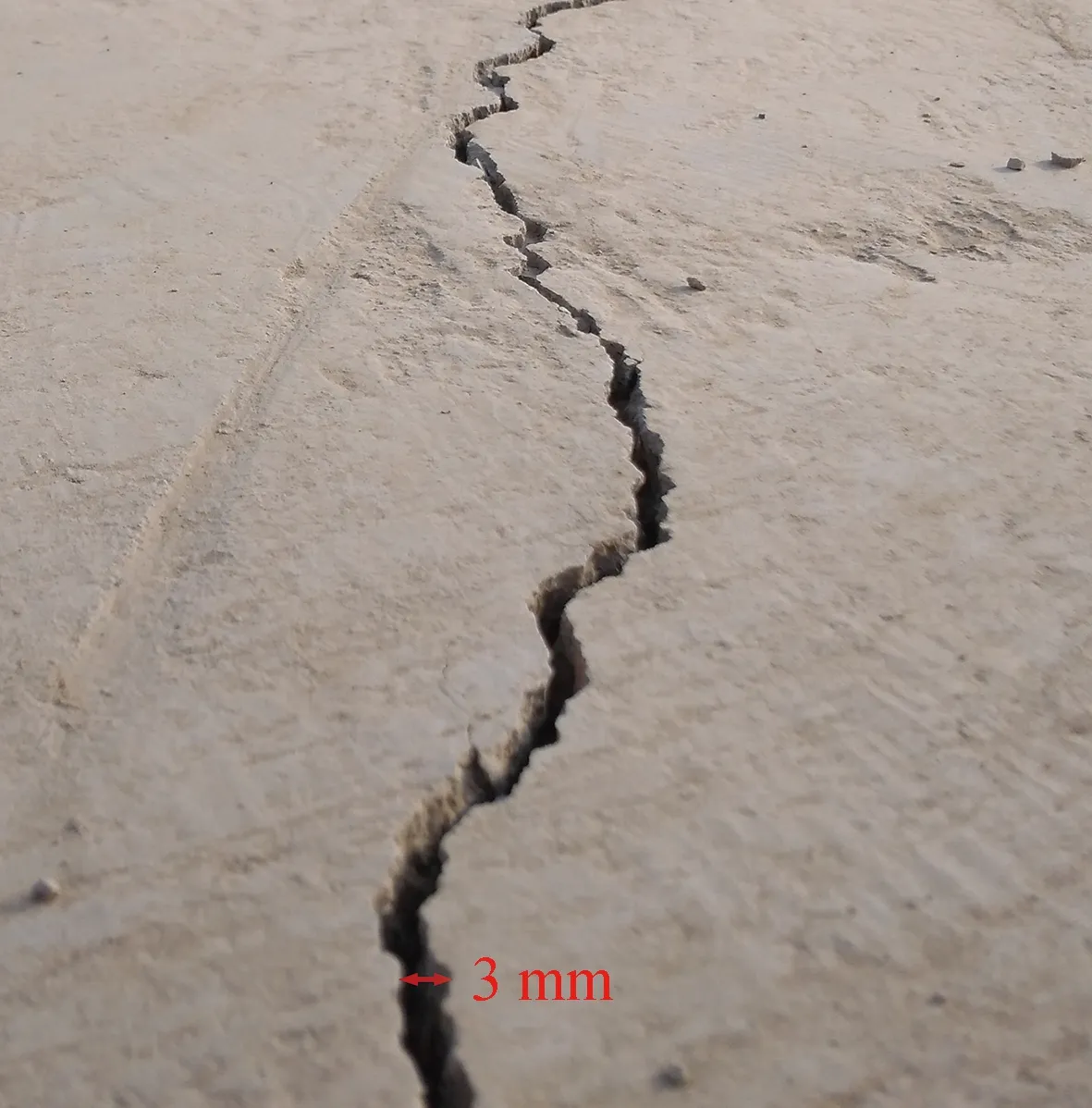
Fig. 8 Crack on the ground surface
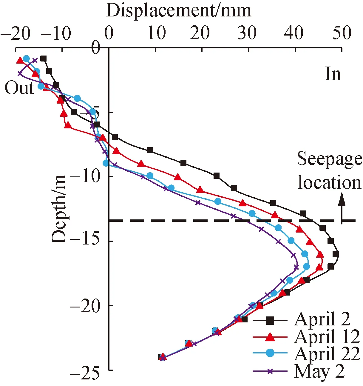
2.2.2Deformationoftheretainingstructure
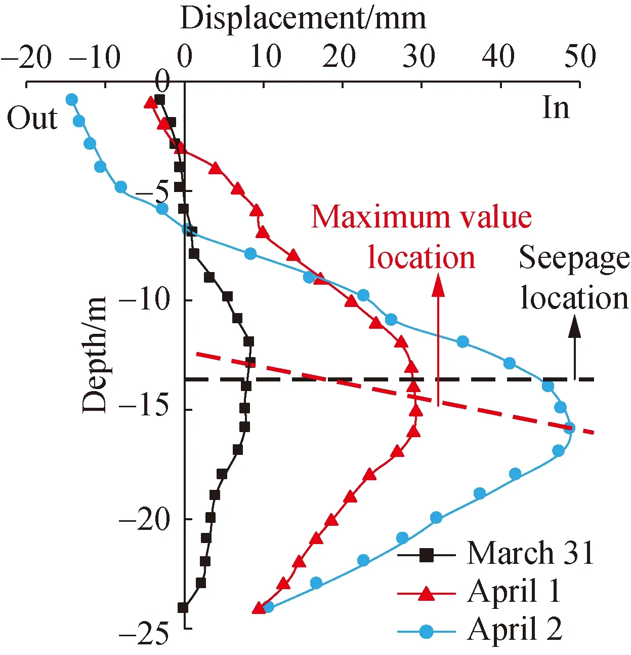
The deformation of retaining structure is shown in Fig.9. The deformation of retaining structure for the monitoring point of ZQT38 far away from the seepage and inrush points was small at the early stage of the case,which showed a spoon shape. The maximum deformation was only 11.7 mm and located near the third support (seepage point). With the increase of seepage and water inflow,the retaining structure on the top moved to the outside of foundation pit and the deformation increased gradually,resulting in the uplift of the ground surface adjacent to the foundation pit (shown in Fig.7). The deformation of retaining structure on the top was up to -15.6 mm by April 2. This was because the seepage leaded to the decrease of water and soil pressure,and then the retaining structure was inclined to some extent,resulting in the upheaval for the monitoring point [shown in Fig. 7(a)]. On April 1,significant displacement occurred in the middle of the retaining structure into the foundation pit,with a change rate as high as 28.8 mm/d. Then on April 2,the displacement continued to increase,reaching a maximum value of 43.5 mm,and the position remained unchanged,but the change rate significantly decreased. The deformation of retaining structure on the bottom remained unchanged except occurring movement of about 10.2 mm toward the inside of foundation pit on April 1,which was mainly due to the inrush at the bottom of foundation pit,resulting in the destruction of soil and reduction of soil strength.
The deformation of retaining structure for the monitoring point of ZQT39 near the seepage and inrush points was similar to that of the monitoring point of ZQT38. Distinctively,the change rate of deformation in the middle of the retaining structure was very large on April 2,with the maximum value as high as 19.7 mm/d,and the location of the maximum value gradually shifted downward. This was due to the influence of the soil loss and soil structure damage caused by seepage and inrush on the monitoring point of ZQT39. It’s worth noting that the deformation for the monitoring points of both ZQT38 and ZQT39 exceeded the warning and control values.

(a) Monitoring point of ZQT38
(b) Monitoring point of ZQT39
3 Analysis on the Reasons of Accident
The layout of dewatering well on the north end side of foundation pit in the construction scheme is shown in Fig. 10,containing two observation wells (G1 and G2),three depressurized dewatering wells (J1,J2 and J3) and three drainage dewatering wells (S1,S2 and S3). However,the actual configuration of wells were completely inconsistent with the requirements,only containing two observation wells (G1 and G2),one depressurized dewatering well (J2) and two drainage dewatering wells (S1 and S2),and the J2 was damaged only two days after it was put into use. The result was that the actual observed water level only decreased 2.00 m,which were far smaller than the requirement of 11.70 m for ③5fine sand layer in the dewatering safety special construction scheme of foundation pit. The water level was complete inconformity with the conditions of foundation pit excavation,and the high water pressure made the retaining structure easy to seepage.
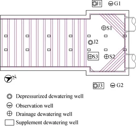
Fig. 10 Layout of dewatering well on the north end side of foundation pit
According to the current standard[18],the inrush stability analysis of foundation pit mainly considered the weight of soil above the confined aquifer and below excavation position to resist the water pressure in the confined aquifer. The calculation formula is
(1)
whereγandγware the unit weights of soil and water,respectively,kN/m3;Dis the soil width above the confined aquifer and below excavation position,m (shown in Fig. 11);hwis the height of confined water head,m;Fis safety coefficient;Fsis critical safety coefficient,1.1-1.3.
The safety coefficients of inrush stability of foundation pit with different excavation depths are calculated and shown in Table 2. The safety coefficients of inrush stability decreased significantly with the increase of the excavation depth. The safety coefficients of inrush stability already reached the critical value of 1.1 when the excavation depth was 12.44 m,which meant that the confined water head needed to be lowered in time to prevent the accident of inrush of foundation pit. It was a pity that the safety coefficient of inrush stability was only 0.65 when the accident occurred based on the survey report and construction log.
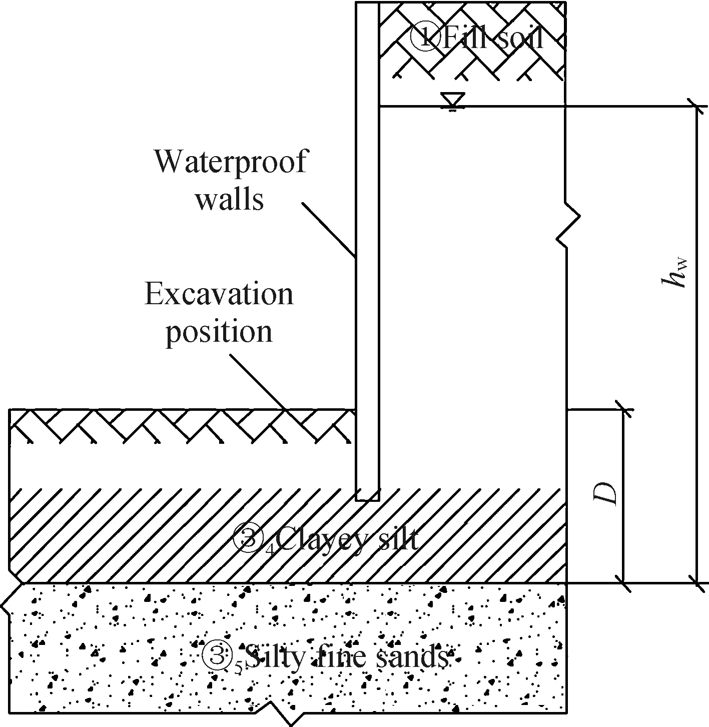
Fig. 11 Schematic diagram of inrush stability analysis
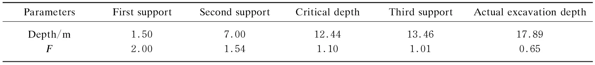
Table 2 Safety coefficients of inrush stability
In addition,the design scheme required that the additional loading and soil storage were not allowed within 10 m of the foundation pit during the excavation and construction of structure,and the construction additional loading beyond 10 m of the foundation pit should be controlled to be no more than 10 kN/m2. However,before the accident,a large amount of steel supports and heavy construction equipment were piled up at the 5 m edge of foundation pit on the north side for a long time,which increased the accumulated surface settlement.
Finally,the contractor stacked the inrush point used sand and stone at the initial stage of the accident,and accelerated the excavation speed to install the fourth steel support at the same time,leading to the emergence of the third inrush point,further increasing the unloading effect and causing further deterioration of the accident.
4 Disposal Measures and Effects of Accident
4.1 Disposal measures of accident
After the accident,the contractor took the following emergency measures to control the further development of the accident (shown in Fig. 12).
On April 2,in view of the problem of the high water level induced by insufficient number of dewatering wells,one drainage dewatering well (S3) was added in foundation pit on the north end side,two depressurized dewatering wells (J1 and J3) were added outside the foundation pit,and at the same time,the damaged depressurized dewatering well (J2) was repaired according to the dewatering scheme. In addition,the filter pipe of the depressurized dewatering wells outside the foundation pit was buried of 34 m depth and located in the confined aquifer,so as to reduce the underground water level and improve the inrush stability of the foundation pit.
On April 6,aiming at the problem of seepage,the grouting near the seepage point after the pile was adopted by constructor in order to form a closed waterproof wall from outside to seal the seepage point and reduce the flow rate of water and sand. At the same time,grouting also reinforced the soil near the seepage point and improved the strength of the soil.
On April 10,in order to solve the problem of excessive surface settlement,the constructors adopted the double-fluid grouting method to reinforce the soil around the seepage point. The reinforcement depth was from the surface of the foundation pit to the excavation surface,and the reinforcement plane dimension was 7 m from east to west of the north end side,and 20 m from south to north. On April 15,no abnormality was found within 3 h after the completion of grouting,and the uplift of ground surface caused by grouting was about 15 mm,indicating the good grouting effect.
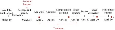
Fig. 12 Construction schedule of the excavation
4.2 Disposal effects of accident
After nearly half a month of treatment and repair,the construction was resumed on April 17,and successfully excavated to the bottom at the north end side of the foundation pit on April 20. Subsequently,the floor cushion and waterproof construction were completed on April 30.
The displacement of ground surface around the foundation pit after the disposal of the accident is shown in Fig. 13. As shown in Fig. 13,after taking the measures on April 2,the displacement of the monitoring points DBC38-1 and DBC39-1 adjacent to the foundation pit changed little,while the displacement of the monitoring point DBC40-1 first decreased significantly and then gradually increased,which was mainly affected by the grouting effect. The displacement of the monitoring points DBC38-2 and DBC40-2 far from the foundation pit also changed little and gradually tended to be stable. However,as the monitoring point DBC39-2 was the closest to the seepage point,it was difficult to control the settlement in a short period of time. On April 12,the settlement was still increasing,and then gradually recovered with the implementation of grouting and precipitation measures,indicating that the treatment measures of the accident had a significant effect.
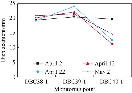
(a) Monitoring points adjacent to the foundation pit
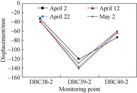
(b) Monitoring points adjacent to the foundation pit
The deformation of retaining structure after the disposal of the accident is shown in Fig. 14. As can be seen from Fig. 14,after the treatment measures were taken on April 2,the horizontal deformation of the retaining structure gradually stabilized and slightly decreased due to the dewatering outside the retaining structure,proving that grouting could effectively reduce the horizontal displacement. This phenomenon was consistent with the experimental results reported by Zhengetal.[19]On May 1,the water level of the observation dewatering well had dropped to -14 m,which significantly reduced the water pressure acting on the retaining structure,resulting that the displacement of the retaining structure to the inside of the foundation pit was recovered.
(b) Monitoring point of ZQT39
To sum up,the accident disposal measures have a good effect and the project can be successfully completed.
5 Conclusions
This paper focuses on the influence of the inrush and seepage on retaining structure and surrounding environment based on a foundation pit accident of Taiyuan metro. The reasons of the accident are also analyzed and a variety of emergency measures are also proposed. The following conclusions can be drawn based on this research.
(1) The occurrence of inrush for foundation pit was the mainly caused by the insufficient dewatering. Hence,corresponding dewatering measures must be taken in areas with high water level.
(2) The displacement of ground surface adjacent to the foundation pit showed a certain degree of uplift,which was contrary to that of ground surface away from the foundation pit,and the settlement of ground surface closed to the seepage location was significant large caused by the loss of water and soil.
(3) The deformation of retaining structure showed a spoon shape,and the retaining structure on the top moved to the outside of foundation pit compared to the inside deformation of other positions. The maximum deformation of retaining structure located near the seepage point,and remained unchanged for the monitoring point far away from the seepage and inrush points,but gradually shifted downward for the monitoring point near the seepage and inrush points.
(4) The development of the accident was effectively controlled by the adding of the dewatering wells,local grouting of retaining structure to stop seepage,surface grouting to reinforcement and uplift soil,and so on,which could provide some guidance for related engineering accidents.
猜你喜欢
金秋(2020年16期)2020-12-09
东坡赤壁诗词(2020年4期)2020-09-02
学生天地(2020年18期)2020-08-25
中学生英语·中考指导版(2020年4期)2020-08-11
现代装饰(2020年6期)2020-06-22
艺术品鉴(2019年10期)2019-11-25
宝藏(2018年1期)2018-04-18
中学语文(2017年25期)2017-01-29
小小说月刊(2016年8期)2016-08-11
小说月刊(2016年5期)2016-05-06
 Journal of Donghua University(English Edition)2020年3期
- Journal of Donghua University(English Edition)的其它文章
- Recent Progress for Gallium-Based Liquid Metal in Smart Wearable Textiles
- Effect of Elastane on Physical Properties of 1×1 Knit Rib Fabrics
- Knowledge Graph Extension Based on Crowdsourcing in Textile and Clothing Field
- Analysis on the Application of Image Processing Technology in Clothing Pattern Recognition
- Clothes Keypoints Detection with Cascaded Pyramid Network
- Encryption and Decryption of Color Images through Random Disruption of Rows and Columns