
Effects of WC-Co reinforced Ni-based alloy by laser melting deposition: Wear resistance and corrosion resistance*
2021-01-21 02:13ZhaoZhenHuang黄昭祯ZhiChenZhang张志臣FanLiangTantai澹台凡亮HongFangTian田洪芳
Chinese Physics B 2021年1期
Zhao-Zhen Huang(黄昭祯), Zhi-Chen Zhang(张志臣),†, Fan-Liang Tantai(澹台凡亮), Hong-Fang Tian(田洪芳),
Zhen-Jie Gu(顾振杰)3, Tao Xi(郗涛)1, Zhu Qian(钱铸)4, and Yan Fang(方艳)1,‡
1School of Mechanical Engineering,Tiangong University,Tianjin 300387,China
2Shandon
g Energy Heavy Equipment Group Dazu Remanufacturing Co.,Ltd,Xintai 271219,China
3Laser Technology Institute,Tiangong University,Tianjin 300387,China
4Tianjin Zhujin Technology Development Co.,Ltd,Tianjin 300230,China
Keywords: WC-Co,wear resistance,corrosion resistance,laser melting deposition
1. Introduction
Hastelloy C276 has been extensively used in the oil,oceanic, and chemical industries due to its excellent strength and corrosion resistance.[1–4]However, low hardness and weak wear resistance have been a problem that limits the application of this material in harsh environments where the wear and the corrosion co-exist. For example, the impeller of agitator used in the petrochemical industry suffers the impact,corrosion,and abrasion of substances such as liquid and powder during the long-term mixing process, which leads to the deformation and defects of the impeller and affects the mixing performance. Therefore, it is necessary to improve the hardness and wear performance of Hastelloy C276,in order to extend the service life of components and reduce costs. Extensive studies have been conducted to improve the properties of Hastelloy C276. For example, Hashim et al.[5]and Yilbas and Ali[6]enhanced the hardness and wear resistance of Hastelloy C276 through laser surface treatment. Mulligan et al.[7]deposited C276 alloy coating with hardness four times higher than that of bulk C276 alloy prepared by plasma enhanced magnetron sputtering.
In addition to the above technology,ceramic particles can be added to the metal material to form a metal matrix composite(MMC)to improve hardness and wear resistance.[8–10]The WC-Co is one of the widely used hard particles due to its high hardness and excellent mechanical properties.[11–13]Up to now,many researchers have paid much attention to WC-Co reinforced composite coatings. Krishna et al.[14]had a conclusion that the wear rate of Al7075-6-wt% WC-Co cermet based composite is lower than that of the unreinforced Al7075 alloy in all applied conditions. Hao et al.[15]studied the wear mechanism of the NiCoCrAlYTa/WC-Co composite coatings,indicating that the hardness of the friction pair plays an essential role in its tribological properties.Gu and Shen[16]reported that high WC-Co content can cause WC reinforced particles to agglomerate obviously in copper matrix composites. Guo et al.[17]reached the same conclusion that the excellent wear resistance of the NiCrBSi/WC-Co composite coatings is related to the synergy among the compact structure,higher hardness,and adhesive strength rather than higher proportion of WC-Co.
Laser melting deposition (LMD) is an important branch of metal additive manufacturing.[18]In the LMD process, the metal powder fed coaxially is melted by a high-energy laser,rapidly solidified and deposited layer by layer. Due to its good net-forming ability,LMD is widely used to manufacture the nickel-based alloys and composite materials with excellent properties.[19–21]
Therefore, the primary purpose of this paper is to fabricate the WC-Co reinforced C276 composite coating without visible defects by laser melting deposition to improve hardness and wear resistance.
Besides, the microstructure and electrochemical corrosion behavior of C276/WC-Co composite coatings are investigated.
2. Materials and methods
2.1. Materials
The substrate is Q235 steel with dimensions of 200 mm×50 mm×10 mm,its surface is cleaned by the laser cleaning machine. The particle sizes of Hastelloy C276 powder are in a range between 60 μm and 140 μm,and its chemical compositions are shown in Table 1. The spherical WC-Co particles(chemical compositions are shown in Table 2) with a size of about 45 μm–100 μm are added into C276 powder,separately,in the proportion of 0,10,15,20 wt%,and then uniformly and mechanically stirred for 60 min at a speed of 1200 r/min in a VC-5 high-efficiency mixer.The morphology of C276 powder and WC-Co powder are shown in Fig.1.

Fig.1. Morphology of powders(a)C276 and(b)WC-Co.

Table 1. Chemical compositions of Hastelloy C276 powder(in unit wt%).
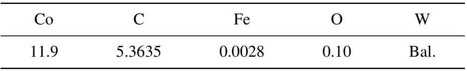
Table 2. Chemical compositions of WC-Co powder(in unit wt%).
2.2. Experimental process
The LMD system consists of fiber laser RFL-C1000(Raycus,laser wavelength 1060 nm,rated output power 1 kW,spot diameter 2 mm), robot (MOTOMAN-MH24, Yaskawa),powder feeder(RC-PGF-D2,Raycham),and chiller(Doluyo).The distance between the coaxial powder feeding nozzle and the substrate was 30 mm. The experiment was conducted in an argon atmosphere(argon was used to feed the powder and prevent the composites from being oxidized). After a large number of process parameter experiments,the flow rate of argon gas was determined to be 5 L/min,and the powder feeding speed was 6.4 g/min.The laser power was 700 W,and the laser scanning speed was 10 mm/s. The 0-, 10-, 15-, and 20-wt%WC-Co composite C276 coatings were manufactured by the above process parameters, and the overlap ratio between two adjacent melt racks was 50%. A schematic diagram of the LMD process and scanning strategy are shown in Fig.2.
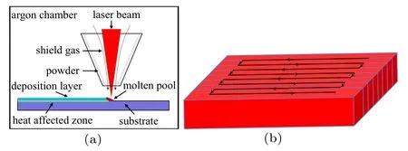
Fig.2. Schematic diagram of(a)LMD process and(b)scanning strategy.
2.3. Properties testing
The composite coatings were cut perpendicular to the laser scanning direction in order to prepare metallographic samples,which were followed by grinding and polishing,and then the samples were etched in an etching solution of HCL:HNO3=3:1. The microstructure and elements distribution were analyzed by metallographic microscope CX40M (Sdptop),scanning electron microscope(SEM)(ZEISS Sigma 300,equipped with x-ray energy spectrometer(EDS),accelerating voltage 15 kV). The phases of the composites were analyzed by D/max-2500 x-ray diffraction (XRD) (Cu target, 40 kV,140 mA).
Hardness values of specimens were measured by a digital hardness tester HV-1000 with a load of 1.96 N and a dwelling time of 10 s. The distance between two adjacent hardness points was 100 μm. Sliding friction coefficient was measured by a test block-ring wear tester M-2000. The material of the grinding ring was GCr15(hardness 60±2 HRC and outer diameter 50 mm). The size of each specimens was 12 mm ×10 mm×10 mm. The wear specimens experienced dry sliding friction tests under a load of 200 N. The rotating speed of the grinding ring was 200 r/min and the wear time was 60 min. Surface morphology of worn specimens was scanned by a phase-shift MicroXAM-3D interferometer.
The electrochemical tests included Tafel potentiodynamic polarization and electrochemical impedance spectroscopy(EIS). All the electrochemical corrosion experiments were conducted in 3.5-wt% NaCl solution on the CHI604 electrochemical workstation with a conventional three-electrode battery at room temperature.In the electrochemical measurement system, a platinum sheet was used as a counter electrode, a saturated calomel electrode (SCE) acted as a reference electrode,and the surface of the samples with an exposed area of 0.3 cm2served as a working electrode. Before Tafel and EIS tests, the working electrode was immersed in 3.5-wt% NaCl solution for 1 h to reach a stable value of the open-circuit voltage (OCP). The EIS was performed in a frequency range of 10-2kHz–105kHz with an amplitude of 10 mV.Potentiodynamic polarization was tested in a potential range from-2 V to 2 V at a scanning rate of 0.01 V/s.
3. Results and discussion
3.1. Microstructure and phase composition
3.1.1. Cross-sectional morphology of composite coatings
The cross-sectional morphologies of composite coatings with different proportions(0,10,15,20 wt%)of WC-Co particles are shown in Fig.3.The average thickness of the composite coatings with two layers are approximately 1.34,1.29,1.51,and 1.23 mm,respectively. In the LMD process,the substrate is melted by a high-energy laser to form a molten pool. The effect of Marangoni convection, gravity, and buoyancy result in a strong fluid flow in the molten pool,[22]causing Fe elements in the substrate to diffuses into the coatings(Fig.3(a)),which indicates a good metallurgical bonding between coatings and substrates. The composite coatings with 0-wt%and 10-wt%WC-Co particles are observed without visible defects.As shown in Figs. 3(b)–3(d), the white WC-Co particles are mostly uniformly distributed in the composite coatings. When WC-Co is added to 15 wt%,defects,big pores(approximately 200 μm) and local cracks appear in the composite coatings.The defects in Fig.2(c)may be the origin of cracks. The longitudinal cracks perpendicular to the laser scanning direction are found in the composite coating containing 20-wt% WCCo. The crack generally originates from the interface between the coating and the substrate, and extends through the WCCo along the temperature gradient, and then passes through the whole composite coatings(Fig.3(d)). In addition,spalling caused by WC-Co particles is found in the composite coating containing 15-wt%and 20-wt%WC-Co.
When the WC-Co content is high,the interaction between adjacent hard particles where WC-Co aggregates is prone to cause structural segregation, resulting in increased structure stress and cracks.[23]Generally, laser energy is more easily absorbed by WC-Co particles than by C276 alloy. Thus,more WC-Co particles will cause a higher temperature gradient and more significant thermal stress with C276 matrix due to the difference in thermal expansion coefficient, which is easy to form cracks.[24]As is well known,LMD is a non-equilibrium solidification process with rapid heating and rapid cooling,which means that the life of the molten pool is very short.As a result,Un-melting WC-Co particles and precipitates hinder the molten pool from flowing, thereby increasing the resistance of the gas to the surface,which is easy to create pores and defects.[25]With the increase of WC-Co particles,the influence of these factors on the composites becomes more critical. Therefore,it can be concluded that the addition of excessive WC-Co particles will lead the pores and cracks to increase in the composite coatings,which accords well with the result reported previously.[17]
Pores, defects, and even cracks are present in the composite coatings containing 15-wt%and 20-wt%WC-Co particles, which is inconsistent with the purpose of improving the wear resistance of the material and extending the service life of components. Therefore,the follow-up research of composite coatings with 15-wt% and 20-wt% WC-Co particles will not be conducted in the following.

Fig.3. Cross-sectional morphology of C276/WC-Co composite coating with WC-Co content of(a)0 wt%,(b)10 wt%,(c)15 wt%,and(d)20 wt%.
3.1.2. Phase composition of composite coatings
The XRD patterns of C276/WC-Co composites are shown in Fig.4. It can be seen that the main phases of C276 alloy are composed of face-centred-cubic(fcc)γ-Ni solution,MoNi,[26,27]while C276/WC-Co composite coating contain new phases, such as α-Co, WC, W2C, and M6C (Co3W3C,Fe3W3C,Ni3Mo3C).[25]
In order to further study the phase composition of composites with 0-wt% and 10-wt% WC-Co particles, the XRD spectra in a range of 2θ =42◦–45◦are amplified (shown in Fig. 4(b)). With the addition of WC-Co particles, the center of the diffraction peaks is shifted. It can be observed that when adding 0-wt% and 10-wt% WC-Co particles, the spectral peaks appear at 43.633◦and 43.489◦, respectively. On the one hand,the W and Co alloy atoms decomposed by WCCo are dissolved into the γ-Ni dendrites in the LMD process,which causes the diffraction peak to shift towards a lower angle due to the atomic radius of the W and Co atoms being larger than that of Ni atom.[28]On the other hand,the residual tensile stress in the composite causes the lattice to anisotropically concentrate and distorte,which also leads the diffraction peak to shift towards a lower angle.[29]Therefore,the position of the diffraction peak in the XRD pattern of the composite is shifted leftwards.

Fig.4. XRD patterns of C276/WC-Co composite coatings with WC-Co content of(a)2θ =20◦–100◦and(b)2θ =42◦–45◦.
3.1.3. Morphology at interface of WC-Co and C276
As can be seen in Fig. 5, Ni, Cr, and Mo in the C276 matrix diffuse into WC-Co particles, C, W, and Co in WCCo diffuse into the matrix, indicating that the WC-Co particles partially melt and have a good metallurgical bond with C276 matrix. Furthermore, according to the EDS results of points 1 and 2(Table 3),there are Mo-rich and W-rich precipitates at the interface of WC-Co and C276 matrix. As shown in Fig.5(c), dendrites grow outwards on the surface of WC-Co.Based on the EDS results at point 2 and point 3,the chemical compositions of dendrite are similar to Mo-rich and W-rich precipitates. When rapid cooling and non-equilibrium solidification start in the LMD process,the partially-melted WC-Co can provide the nuclei for heterogeneous nucleation and the growth of dendrites at the interface between WC-Co and C276 matrix is related to the melting degree of WC-Co particles.

Table 3. EDS results of element content at different points in Fig.5(in unit wt%).

Fig. 5. (a)–(c) Microstructures and (d)–(f) SEM line scanon edge of WC-Co particles (line scan from bottom to top, with black line referring to scanning position).
Figure 6 shows the microstructures in the middle of composite coatings with different content values of WC-Co,which are mainly composed of parallel dendrites and interdendritic eutectics. The central microstructure of composites is mainly coarse Ni-rich primary dendrites(Fig.6(a)). According to the EDS analysis in Table 4,the primary Ni-rich dendrites(A and C)are γ-Ni solid solutions in which elements Cr,Mo,W,Fe,Co are dissolved. In addition, it can be observed that the eutectic region is rich in W,Mo and depleted in Ni,Fe,Co compared with the dendrite region. The remaining liquid becomes rich in Mo and W due to the rejection of these elements into the liquid phase during the solidification, giving rise to eutectic phase frozen with higher contents of Mo and W. This phase is confirmed by EDS and XRD, with MoNi serving as a solid solution.[27]Comparing with C276 alloy without WCCo particles, more content of W is dissolved in the dendrite and eutectic regions.
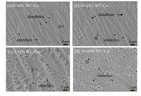
Fig. 6. Microstructures in the middle of C276/WC-Co composite coatings with WC-Co content of[(a)and(c)]0 wt%and[(b)and(d)]10 wt%.

Table 4. EDS analysis of element content at different points in Fig. 6(in unit wt%).
3.2. Hardness
Figure 7 shows the hardness curves of C276/WC-Co composite coatings along the depth direction of coatings. The undissolved WC-Co particle area in the coatings is avoided during the hardness test. The average hardness of the composite coating containing 10-wt% WC-Co (447 HV0.2) is 1.26 times higher than that of the C276 alloy (356 HV0.2). Enhancement of hardness can be achieved by solid solution hardening,precipitation,dispersion,and microstructure refinement as well as by work hardening.[30]When WC-Co is decomposed in the molten pool,W and Co elements are solid-solved into the γ-Ni dendrites and eutectic region,which plays a role in the solid solution strengthening of composite coatings. Besides, the precipitates rich in Mo and W(as shown in Fig.4)and WC-Co particles can block the movement of dislocations,resulting in the improvement of the hardness of the composite coatings.

Fig. 7. (a) Microhardness plots of C276/WC-Co composite coatings with different WC-Co content values and(b)average microhardness.
3.3. Wear resistance
The variations of friction coefficient of C276/WC-Co composite coatings with sliding distance under dry sliding test condition at room temperature are shown in Fig.8(a). As the sliding cycles of wear increases, the friction coefficient tends to be stable. The average friction coefficient of C276 alloy is 0.66 in the stable stage. However, the friction coefficient of the composite coating with 10-wt%WC-Co particles first decreases and then tend to stabilize. In the initial stage of wear,the C276 matrix is first worn, and the friction coefficient has a maximum value of 0.59 at this time. As the wear process progresses,the C276 matrix and WC-Co particles are worn together. The friction coefficient decreases to a minimum value of 0.51, and then increases to 0.55 in the stable stage. It can be seen that the friction coefficient of the composite coating with 10-wt%WC-Co is lower than that of C276 coating at all stages. As is well known, the friction coefficient is inversely proportional to the corresponding hardness.[31]The hardness of the composite coating with 10-wt%WC-Co is higher than that of pure C276 coating. As mentioned above, the precipitates rich in Mo and W and WC-Co particles to improve the hardness of composite coatings, which also results in the improvement of their wear resistance. Figure 8(b) shows that the wear mass loss and wear rate of sample decrease as the WC-Co increases. The wear mass losses of composites with 0-wt% and 10-wt% WC-Co are 0.2437 and 0.0131, respectively. The wear rate of composite coating containing 10-wt%WC-Co (6.95×10⁻³mg/m) is just 3.5% of that of C276 alloy (196.23×10⁻³mg/m). This result shows that the wear property of composite is significantly improved.

Fig.8.(a)Friction coefficient of C276/WC-Co composite coatings with different WC-Co content values and (b) wear mass loss and wear rate versus WC-Co content.
In order to further study the wear mechanism of C276/WC-Co composite coatings,the surface morphology of the sample after dry sliding wear and the schematic diagram of the wear process are shown in Figs.9 and 10,respectively.The wear degree of the composite coating with 10-%wt WC-Co is significantly lower than that of the C276 coating without WCCo. It can be observed that the wear surface of the C276 alloy has many visible plowing grooves and spalling pits as well as severe plastic deformation (Fig. 9(a)), suggesting that adhesive wear and abrasive wear occur in the wear process.[15,32]At the beginning of dry sliding wear,the surface of the coating directly contact the grinding ring,and cold-welding points are generated at the contact points. With the proceeding of the dry sliding wear process, welding points are cut and fall off the coating to become abrasive debris, which leads the spalling pits to appear on the coating surface. At this time,the friction interface changes from the friction between the wear ring and the coating to the friction among the wear ring, the coating and debris. In the wear process,the abrasive wear occurs and plowing grooves appear on the coating surface.

Fig.9. Morphologies of samples with WC-Co content of(a)0 wt%and(b)10 wt%after dry sliding wear.
Figure 9(b) shows that the plowing grooves appear on the surface of the sample, indicating that abrasive wear dominates the composite coating containing 10-wt%WC-Co. After adding WC-Co,the plowing grooves on the surface of the coating becomes shallow. The C276 matrix coated on the surface of the WC-Co particles is preferentially worn until the WC-Co particles are exposed (Fig. 10(b)). The WC-Co particles are hard to pull out from the C276 matrix due to the excellent bonding between the two. And the high hardness WC-Co particles increase the resistance of the friction pair,which can protect the C276 matrix from being cut from wear ring in the dry sliding wear process to restrain abrasive wear(Fig. 10(c)).[33]Besides, the higher hardness of the composite coating containing 10-wt% WC-Co than that of the C276 coating is also a reason for improving the wear resistance.
The wear tracks on the sample surface after dry sliding wear are shown in Fig. 11. The wear degree can be characterized by the depth and width of the wear. Obviously, it can be seen from the three-dimensional morphology that the C276 coating is severely worn, and its wear depth and width are 388 μm and 8.14 mm, respectively. Comparing with the C276 coating without WC-Co,the wear depth(113 μm)of the composite coating containing 10-wt%WC-Co is significantly shallower, and the wear width (2.17 mm) is narrower, indicating that only slight wear occurs. This result indicates that the addition of WC-Co particles can significantly improve the wear resistance of Hastelloy C276.

Fig.10. Schematic diagram of wear process.

Fig.11. Three-dimensional surface profile of worn tracks of samples with WC-Co content of(a)0 wt%, (b)10 wt%, (c)depth and width curves of worn tracks,after dry sliding wear.
3.4. Electrochemical corrosion behavior of composite coatings
Figure 12 shows the potentiodynamic polarization curves of C276/WC-Co composite coatings with different WC-Co content values in a 3.5-wt% NaCl solution. Table 5 shows the relevant parameters obtained from the polarization curve,such as corrosion current density (icorr), corrosion potential(Ecorr), and polarization resistance (Rp), passive current density(ip). Typically,the corrosion potential represents the thermodynamic trend of the corrosion process.

Table 5. Electrochemical parameters obtained from polarization curves of samples with different WC-Co content values.

Fig. 12. Potentiodynamic polarization curves of C276/WC-Co composite coatings with different WC-Co content values in 3.5-wt%NaCl solution.
Obviously, the corrosion potential of composite coating containing 10-wt% WC-Co is lower than that of C276 coating, indicating that it is easier for corrosion reactions to happen. The corrosion current density (icorr) of composite coating containing 10-wt%WC-Co(8.852 μA/cm2)is higher than that of C276 coating (3.657 μA/cm2), which means that the corrosion rate of 10-wt%composite coating is faster. The polarization resistance of composite coating containing 10-wt%WC-Co (4.918 kΩ/cm2) is only 41% that of C276 coating(11.861 kΩ/cm2). It can be observed from potentiodynamic polarization curves that the composite coatings contain 0-wt%and 10-wt% WC-Co have obvious passivation zones (ΔE,1 and ΔE,2),demonstrating that both samples have evident passivation behaviors. Generally, the lower passive current density(ip)means the difficult passivation of the alloy.[34]Compared with the C276 coating without WC-Co, the composite coating containing 10-wt%WC-Co is prone to electrochemical corrosion due to the higher ipvalue.
Figure 13 shows the EIS results of C276/WC-Co composite coatings with different WC-Co content values in 3.5-wt%NaCl solution. Equivalent circuits of composite coatings containing 0-wt%and 10-wt%WC-Co for fitting the EIS data are R(Q(R(CR)))and R(Q(RW))(CR),respectively. In the equivalent circuit, Rsis the solution resistance, CPE1is the constant phase element, Rctis the charge transfer resistance, Rfrefers to the film resistance of the passive film,Rwrepresents the Warburg impedance caused by semi-infinite diffusion,Cdland Cfcorrespond to the double-layer capacitance and the capacitance of the passive film, respectively. The χ2values of composite coatings containing 0-wt%and 10-wt%WC-Co are 2.65×10⁻³and 2.65×10⁻⁴,respectively,indicating a good fit between the equivalent circuit and experimental results. The fitting results of EIS data are summarized in Table 6. The Rctand Rfvalue of composite coating containing 10-wt%WC-Co are only 26%and 3%that of C276 coating,respectively. This reveals the fact that the corrosion resistance of composite coating containing 10-wt%WC-Co is reduced compared with that of C276 coating. As is well known, the larger the capacitor arc radius, the impedance modulus values |Z|, and the maximum phase angle,the better the electrochemical corrosion resistance of the material is.As can be seen in Figs.13(b)–13(d),the capacitor arc radius,the impedance modulus and the maximum phase angle of composite coatings containing 10-wt%WC-Co are all smaller,which is consistent with the results of potentioldynamic polarization, so the corrosion resistance of the composite coating with 10-wt% WC-Co decreases. This phenomenon is because of the increasing content of carbides after adding WC-Co,which leads the number of galvanic cells to increase in the coating, and thus quickening the electrochemical corrosion rate.
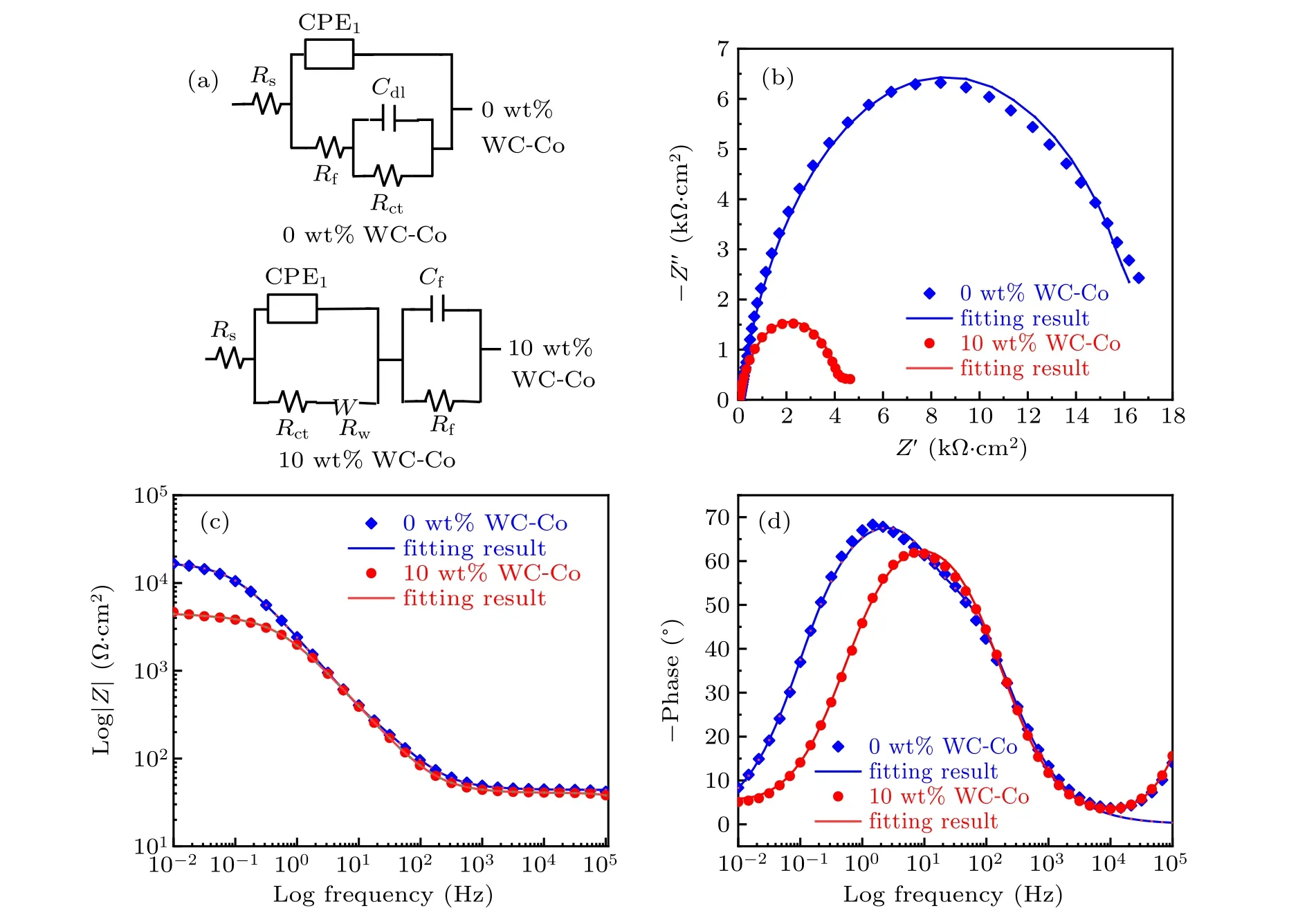
Fig.13. EIS results of C276/WC-Co composite coatings with different WC-Co content values: (a)equivalent circuit,(b)Nyquist diagram,[(c)and(d)]Bode diagram.
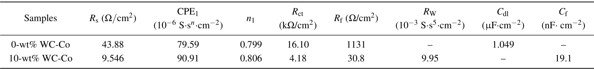
Table 6. Fitting results of EIS data for samples with different WC-Co content values.
4. Conclusions
The C276/WC-Co composite coatings with different WCCo content values are fabricated by LMD.The microstructure,hardness, wear performance, and electrochemical corrosion behavior are measured and analyzed. The main conclusions can be drawn below.
(i)The composite coatings with 0-wt%and 10-wt%WCCo particles are observed to have no obvious defects. The longitudinal cracks caused by structural segregation and thermal stress are found respectively in the composite coatings containing 15-wt%and 20-wt%WC-Co particles.
(ii) The main phases of C276 alloy are composed of fcc γ-Ni solution and MoNi,while C276/WC-Co composite coatings contain new phases,such as α-Co,WC,W2C,and M6C.
(iii)The WC-Co particles are uniformly distributed in the composite coatings. The growth of dendrites at the interface between WC-Co and C276 matrix is related to the melting degree of WC-Co particles.After adding WC-Co,nano-eutectics are finer and more clearly distributed between the dendrites.
(iv) The C276/WC-Co composite coating shows higher hardness and better resistance wear than C276 coating,which can be attributed to the increase of the number of hard particles as well as the protective effect of WC-Co.
Comparing with C276 coating, the electrochemical corrosion resistance of the C276/WC-Co composite coating decreases due to the increasing of carbide content.
- Chinese Physics B的其它文章
- Two-dimensional finite element mesh generation algorithm for electromagnetic field calculation*
- Stable water droplets on composite structures formed by embedded water into fully hydroxylated β-cristobalite silica*
- Surface active agents stabilize nanodroplets and enhance haze formation*
- Synchronization mechanism of clapping rhythms in mutual interacting individuals*
- Theoretical study of the hyperfine interaction constants,Land´e g-factors,and electric quadrupole moments for the low-lying states of the 61Niq+(q=11,12,14,and 15)ions*
- Ultrafast photoionization of ions and molecules by orthogonally polarized intense laser pulses: Effects of the time delay*