
Spatio-temporal measurements of overshoot phenomenon in pulsed inductively coupled discharge∗
2021-05-06 08:55XiangYunLv吕翔云FeiGao高飞QuanZhiZhang张权治andYouNianWang王友年
Chinese Physics B 2021年4期
关键词:王友
Xiang-Yun Lv(吕翔云), Fei Gao(高飞), Quan-Zhi Zhang(张权治), and You-Nian Wang(王友年)
Key Laboratory of Materials Modification by Laser,Ion,and Electron Beams(Ministry of Education),School of Physics,Dalian University of Technology,Dalian 116024,China
Keywords: pulse inductively coupled plasma,overshoot,spatial distribution
1. Introduction
Pulse inductively coupled plasma (PICP) is widely used in various applied fields(semiconductor etching,surface modification, thin film deposition) due to its high etch selectivity and high etch rate, strong controllability of plasma parameters,good uniformity,and small substrate damage. Therefore,the characteristics in pulse inductively coupled plasma have been widely studied.[1–7]Kushner et al.[8]discussed the calculation results of pulsed ICP(power matching dynamics)by using a fixed impedance matching network and their influences on plasma characters. They found that H mode delays due to power mismatch in E mode. Then they used high-low pulsed power to adjust the minimum plasma density, which reduces ignition delay and enhances plasma stability.[9]Han et al.[10]measured the time-resolved magnetic field, electron density,and electron temperature for pulsed argon plasma. They found that a “ring” shape density profile appears at the initial stage of discharge,which then evolves to a peak in the middle of the chamber.
In the investigations of pulsed discharge, the time evolution curve of plasma parameters (electron density, electron temperature, and relative light intensity) often has the phenomenon of overshoot at the initial pulse,[11–15]i.e.,they first increase to maximum and then drops to a stable value. Sirse et al.[16]observed overshoot phenomenon during pulse off when measuring electron density in oxygen plasma, and established a qualitative model to explain the variation trend of negative ion density and temperature. The overshoot and undershoot of coils current is greatly weaken by using exponentially rising control signals by Ye et al.[17]In the pressure range of 27 kPa–101 kPa, the overshoot in coils current of Ar–H2plasma is obvious,while the overshoot phenomenon in Ar–N2plasma almost vanishes with rising pressure.Subramonium et al.[18]simulated argon plasma by employing a twodimensional plasma model. Their models capture the overshoot of the electron temperature at the start-on-time, which become even more pronounced at low frequencies. Kwon et al.[19]analyzed the influence of time-varying edge-centre density ratio(h factor)on plasma parameters,and solved the space average transport equation in a self-consistent way. They found that when the h factor decreases, the electron temperature decreases at the active-glow,and the overshoot behavior of the electron temperature gradually disappears.
In industry,overshoot phenomenon is an important issue which has effect on the uniformity of plasma and generating high-energy ions,which could damage the chip.The study of overshoot phenomenon is beneficial to understand it and improve the uniformity of plasma. The temporal evolutions of input power and electron density in Ar and Ar/CF4pulsed ICP were investigated by Gao et al.[20]They found that the input power appears two peaks and the electron density presents an overshoot during the initial pulse-on stage, and the overshoot decays at lower powers and higher pressures. The work in this paper goes into the previous work by focus more on the dependence of overshoot phenomenon on spatial positions. In fact,the closer to the coils and the discharge centre,the more obvious overshoot phenomenon appear,that is,stronger radio frequency induction field generally induces more pronounced overshoot phenomenon.
In this work the temporal evolutions of the electron density and the relative light intensity in pulsed ICP are studied.The organization of this paper is as follows. In Section 2,descriptions of the experimental device are provided. In Section 3, experimental results of the time evolutions of electron density and relative light intensity in axial and radial distributions are given. Overshoot phenomenon appears near the coils location and varies at different spatial positions. Finally,a short conclusion will be given in Section 4.
2. Experimental setup
The experimental setup for this study is schematically shown in Fig.1. The ICP reactor is comprised of two planar spiral copper coils, which are cooled by recycling water inside. The coils have been energized by a 13.56-MHz radio frequency (RF) power through a matching network. The grounded substrate with a diameter of 26 cm, is placed at 10.5 cm below the quartz window. The vacuum reactor is connected to a turbine molecular pump and a mechanical pump,and the base pressure of the reactor can reach 10−3mTorr(1 Torr=1.33322×10²Pa). More detailed description of the reactor can be found in our previous works.[21–23]A timeresolved power diagnostic system (Octiev Suite VI probe,Impedans,Ltd.),fixed between the matching network and the power source, can measure the instantaneous RF power and display complex waveform.
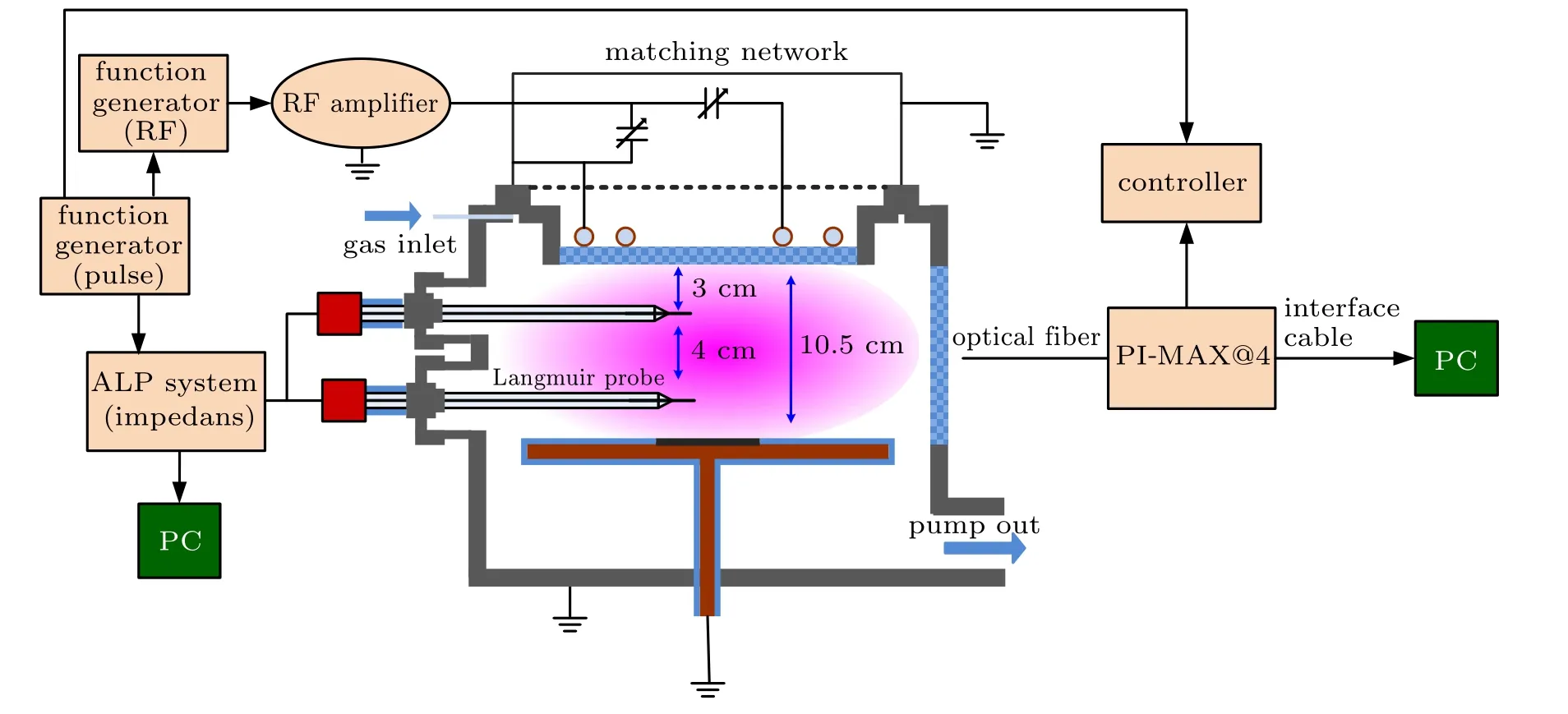
Fig.1. The schematic diagram of the experimental apparatus.
In addition,the temporal evolution of the electron density is measured by a commercial Langmuir probe,which is set at 3.0 cm and 7.0 cm away from the quartz window,and can be moved from the side wall to the centre of the chamber. The probe tip(5 mm in length and 0.2 mm in diameter)is made of tungsten wire.
The plasma was generated by planar coils with a pulsed power of 13.56 MHz. The pulse frequency is 1 kHz with 50%duty cycle. The gas used in this paper is pure Ar and Ar/CF4mixture gas. The total flow rate is fixed at 50 sccm (standard cubic centimetres per minute). The pressure is between 1 mTorr and 80 mTorr, suitable for most plasma processing applications. The power is varied from 200 W to 700 W.
3. Results and discussion
3.1. Axial distribution in Ar discharge
In Fig.2,the temporal evolutions of the relative intensity(a),electron density(b),and effective electron temperature(c)for different axial positions are given at 10 mTorr, 300 W, in Ar discharge, with a pulse frequency of 1 kHz and 50%duty cycle. The electron density and effective electron temperature are measured by Langmuir probe at 3 cm and 7 cm from coils at the discharge centre,due to the probe measurement limitation. The relative light intensity measurement is a line integral,measured every 2 cm by an optical probe at axial 1 cm–9 cm from the coils. We selected the strongest spectral line 811.5 nm,which is excited from Ar(2P9). There are two kinds of energy level transitions,see Eqs.(1)–(3),one direct excitation from ground state(Ar(1S0))with a threshold of 13.08 eV,the other is excited by the metastable state (Ar(1S5)) in two steps excitation with a threshold of 1.53 eV.[24,25]

In Fig.2(a),when the power is applied,the relative light intensity at all positions first increases rapidly and then decreases. This is the so-called overshoot phenomenon(marked in Fig.2),which can be explained by the generation and transmission of plasma.[23]At the initial stage of the pulse,the remaining electrons in the previous pulse period are heated to high-energy electrons, promptly. Due to the relatively high temperature of electrons, the consequent ionization rate is higher than the loss rate of electrons. The plasma density finally reaches a steady state with convergent density. The overshoot phenomenon is distinct at various positions. As seen in Fig.2(a),the overshoot phenomenon is obvious near the coils(1 cm–5 cm). With the increase of axial distance, the overshoot phenomenon gradually decays. At 3 cm, the overshoot is about 19.4% higher than that in stable period. However,there is almost no overshoot at 9 cm. This is because that there are pretty few residual electrons left from the previous period,which allows the RF field to penetrate into a deep position at initial pulse-on stage. The residual electrons can respond instantly to the RF field and are heated into high-energy. The number of high-energy electrons decreases at a deeper location with reduced RF electric field,which can be revealed from the reduced high-energy tail(around 5 eV smaller)in EEPF at 7 cm than at 3 cm,resulting in lower ionization rate and excitation rate. The overshoot phenomenon thus becomes weaker when locating away from the coil.
In addition,with the increase of axial distance, the overshoot phenomenon delays. For instance, it takes about 75 µs for the plasma to reach the maximum value at 3 cm, while it takes about 200 µs at 9 cm. This is because on one hand the energy near the coils is first coupled into the plasma, which takes a certain time to diffuse downward. On the other hand,the RF electric field strength is greater close to the coils,producing more high-energy electrons (as shown in Fig.3), the ionization rate and excitation rate are high, and the electron density and light intensity grow rapidly. Whereas, the light intensity increases slowly and the overshoot phenomenon decays at the location with a larger distance away from the coils.In addition,the strength of light intensity during pulse on first increases and then decreases slightly with the increase of the axial distance.[26]The light intensity at all positions immediately decreases to 0,when the power is turned off.
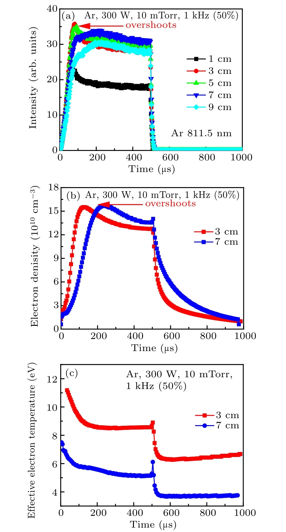
Fig.2. Temporal evolutions of the relative intensity of 811.4 nm for different axial positions(a),the electron density(b),and the effective electron temperature(c)at 10 mTorr,300 W in Ar discharge,with a pulse frequency of 1 kHz and 50%duty cycle.
Figure 2(b) exhibits the temporal evolutions of the electron density at different axial positions measured by Langmuir probe. Similar to the evolutions in Fig.2(a), when the power is turned on, the electron density first increases to a peak value,then decrease to a convergent value,i.e.,the overshoot phenomenon appears. When the power is turned off,the electron density first rises slightly to a peak and then significantly decrease. This density peak may be caused by the release of charge by capacitance and inductance in RF power resource.[20]
Figure 2(c) displays the temporal evolutions of effective electron temperature at different axial positions. It can be seen from the diagram that the effective electron temperature is high when the power is turned on, and then decreases gradually. This change is with opposite trend of electron density(Fig.2(b)). It can be explained that when the power is turned on, the energy is directly coupled to a small amount of electrons left from the previous pulse period, producing high energy electron, and inducing very high electron temperature.The electron density increases due to the intense collisions caused by high energy electrons, while the average coupling power of a single electron gradually decreases, leading to a decreased effective electron temperature. When the electron density is stabilized, the effective electron temperature also reaches a stable value. After the power is turned off,the effective electron temperature drops rapidly. The effective electron temperature at 3 cm is always higher than that at 7 cm (with lower density).
The EEPFs evolutions at different times with axial height of 3 cm and 7 cm are given in Fig.3. As can be seen from the figure, there are abundant high energy electrons at the early stage of pulse-on (50 µs), which dominates the initial discharge. These high energy electrons are mainly produced by the fact that the power is coupled to a small number of electrons at the initial stage of active-glow.This corresponds to the low electron density and high effective electron temperature at the initial active-glow, as shown in Figs. 2(b) and 2(c). Furthermore, the EEPF shows a maximum of high-energy electrons at 75 µs, which corresponds to the time of the overshoot in measured light intensities at 3 cm. When the plasma reaches the steady state, the electron energy distribution becomes rather stable(after 150µs).In addition,the high-energy electron tails in EEPF at 7 cm are relatively lower than that at 3 cm,due to the reduced RF field at 7 cm.

Fig.3. EEPFs at different times with axial height of 3 cm(a)and 7 cm(b),at 10 mTorr,300 W,Ar discharge. The pulse frequency of 1 kHz with 50%duty cycle.
3.2. Axial distribution in Ar/CF4 discharge
Figure 4 reveals the temporal evolutions of the relative light intensities,the electron density,and the effective electron temperature at different axial positions at 10 mTorr, 300 W,Ar/CF4=90/10 discharges,with a pulse frequency of 1 kHz and 50%duty cycle. It is obvious that the temporal evolution of relative light intensities in Ar/CF4discharges exhibit similar characteristics with Ar discharges(Fig.2(a)). But the intensities decrease monotonously when increasing the axial distance from 3 cm to 9 cm away from the coils.
The temporal evolutions of electron densities (shown in Fig.4(c)), measured by Langmuir probe, have similar trend with the relative light intensities, i.e., the electron density at 3 cm is about 1.75 times the value at 7 cm when the discharge approaches steady. It is worth noting that, the overshoot at 3 cm in Ar/CF4discharge is obviously smaller than that in pure Ar discharge, which almost presents no overshoot at 7 cm.Furthermore, it takes only 70 µs to reach the steady state in Ar/CF4discharge, which takes about 200 µs in pure Ar discharge. This is probably due to that there are much more collision reactions in Ar/CF4discharge, and consequently more loss channels of electrons (especially high energy electrons),limiting the development of overshoot phenomenon.[27,28]
Figure 4(d) displays the temporal evolutions of the effective electron temperature measured by Langmuir probe at different axial positions. The evolution of the effective electron temperature also exhibits the same trend with pure Ar discharge, i.e., the electron temperature is pretty high when the power is turned on, and then decreases to a stable value, and finally becomes very small when the power is turned off.
In Fig.5, the EEPFs at different time at 3 cm and 7 cm(axial distance from the coils)are shown at 10 mTorr,300 W with Ar/CF4=90/10 and the pulse frequency of 1 kHz and 50% duty cycle. As can be seen from Fig.5(b), the time for EEPF to reach the steady state is pretty short,which only took 75 µs at 7 cm in the Ar/CF4discharge. This is again due to the existence of more collision mechanisms in the Ar/CF4discharge.

Fig.4. Temporal evolutions of the relative intensities of Ar 811.4 nm(a)and F 641.4 nm(b),the electron density(c),and the effective electron temperature(d)for different axial positions at 10 mTorr,300 W,in Ar/CF4 (90/10)discharge,with a pulse frequency of 1 kHz and 50%duty cycle.

Fig.5. The EEPFs at different resolve times at 3 cm and 7 cm(axial distance from the coils),at 10 mTorr,300 W,Ar/CF4=90/10 and the pulse frequency of 1 kHz and duty 50%cycle.
3.3. Radial distribution
Figure 6 reveals the temporal evolutions of the electron density for different radial positions at 3 cm and 7 cm (axial distance from the coils) in Ar and Ar/CF4=90/10 discharges at 10 mTorr, 300 W, measured by Langmuir probe,with a pulse frequency of 1 kHz and 50% duty cycle. It can be seen from the diagram that the rising time of electron density at all radial positions are similar,which indicates that the plasma in the horizontal direction almost respond to the power supply at the same time when the pulse is turned on.
The electron density gradually becomes smaller when approaching the reactor wall, and the overshoot phenomenon is most pronounced at the positions near the coils and the centre. With the increase of the radial and axial distances (from the centre and coils),the overshoot phenomenon gradually decays. In Ar/CF4discharge, the overshoot is significantly reduced with respect to the pure Ar discharge, due to the more collision mechanisms in CF4discharge.
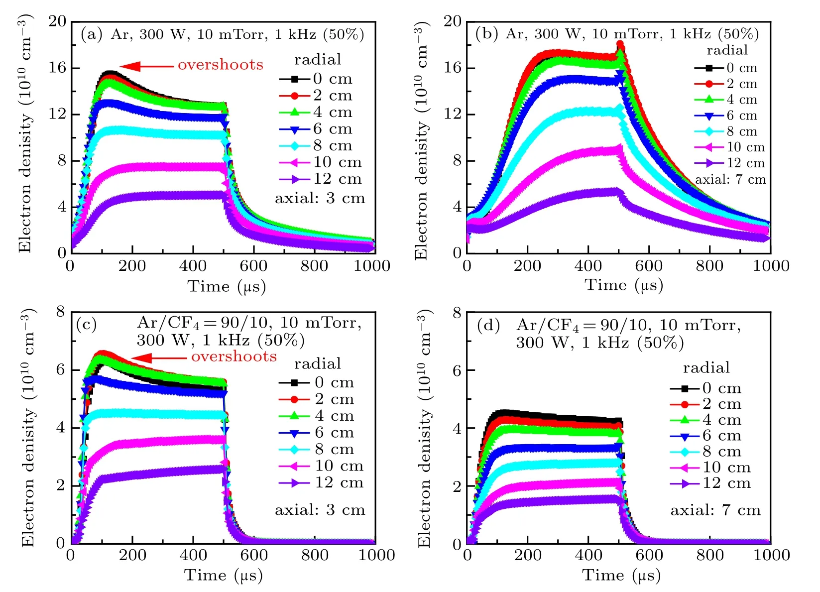
Fig.6. Temporal evolutions of the electron density at different radial positions at 3 cm(a)and 7 cm(b)in Ar discharge,3 cm(c)and 7 cm(d)in Ar/CF4=90/10 discharge at 10 mTorr,300 W,measured by Langmuir probe,with a pulse frequency of 1 kHz and 50%duty cycle.
4. Conclusions
In this work, we report for the first time the relationship between overshoot phenomenon and spatial positions in pulsed inductively coupled Ar and Ar/CF4discharges. The electron density, effective electron temperature, and relative light intensity at different spatial positions were measured by using a time-resolved diagnostic system,i.e.,Langmuir probe and optical probe, under the conditions of pulse frequency of 1 kHz and duty cycle of 50%.
In pure Ar discharges, when the power is turned on, the relative light intensity first increases to a peak value,then falls to a stable value, i.e., the overshoot appears, which is related to the generation rate and loss rate of electrons. With the increase of axial position,the overshoot phenomenon decays and the time consumed for the relative light intensity to reaches the maximum becomes even longer,for instance it takes about 75 µs at 3 cm but 200 µs at 9 cm. The temporal evolutions of electron density are similar to those of relative light intensity,but the electron density at 3 cm responds faster to power supply comparing to the case at 7 cm, as the radio frequency electric field is stronger and consequently the number of highenergy electrons is larger for the position closer to the coils.
The effective electron temperature is pretty high when the power is turned on,then gradually decreases to a stable value,and finally significantly decrease after the power is turned off.Therefore,the high-energy electrons dominate the discharge at the initial stage of the pulse,which is supposed to play a role in the overshoot phenomenon. The effective electron temperature is always higher for the position near the coils due to the stronger electric field.
In Ar/CF4discharge, the temporal evolutions of relative light intensity have very similar trend with Ar discharge. But the relative light intensity greatly decreases when increasing the axial position from 3 cm to 9 cm away from the coils,and the overshoot phenomenon becomes much weaker, which is probably due to the more collision reactions in Ar/CF4discharge,inducing rapid reduction of high energy electrons.
Furthermore,the overshoot phenomenon and plasma density are found to be more pronounced near the reactor centre,which gradually decays when approaching the reactor wall.
猜你喜欢
Chinese Physics B(2022年8期)2022-08-31
Plasma Science and Technology(2022年5期)2022-06-01
Plasma Science and Technology(2022年5期)2022-06-01
Plasma Science and Technology(2022年2期)2022-03-10
Plasma Science and Technology(2021年11期)2021-11-30
Chinese Physics B(2021年9期)2021-09-28
Plasma Science and Technology(2021年9期)2021-09-10
Plasma Science and Technology(2021年5期)2021-05-22
Plasma Science and Technology(2021年3期)2021-03-22
Chinese Physics B(2021年3期)2021-03-19

- Chinese Physics B的其它文章
- Speeding up generation of photon Fock state in a superconducting circuit via counterdiabatic driving∗
- Micro-scale photon source in a hybrid cQED system∗
- Quantum plasmon enhanced nonlinear wave mixing in graphene nanoflakes∗
- Restricted Boltzmann machine: Recent advances and mean-field theory*
- Nodal superconducting gap in LiFeP revealed by NMR:Contrast with LiFeAs*
- Origin of itinerant ferromagnetism in two-dimensional Fe3GeTe2∗