
Numerical study of the grid erosion of field emission electric propulsion
2021-10-31 08:14ChangLU鹿畅YangLUO罗杨GuangqingXIA夏广庆HuiGAO高辉andNuoXU许诺
Plasma Science and Technology 2021年10期
关键词:许诺
Chang LU (鹿畅), Yang LUO (罗杨), Guangqing XIA (夏广庆),Hui GAO (高辉) and Nuo XU (许诺)
1 State Key Laboratory of Structural Analysis for Industrial Equipment, Dalian University of Technology,Dalian 116024, People’s Republic of China
2 Key Laboratory of Advanced Technology for Aerospace Vehicles of Liaoning Province, Dalian University of Technology, Dalian 116024, People’s Republic of China
3 Beijing Institute of Mechanical Equipment, Beijing 100854, People’s Republic of China
Abstract In this paper,the immersed finite element particle-in-cell Monte Carlo collision(IFE-PIC-MCC)model is used to study the cause of the grid erosion in field emission electric propulsion(FEEP).The simulation results show that charge exchange (CEX) ions are the main cause of the grid erosion, while beam ions basically do not impinge on the grid.The CEX ions are mainly generated near the grid.Some of these CEX ions return to the upper surface, lower surface and notch side surface of the grid.The impact angle of CEX ions returning to the upper and side surfaces is large, but their energy is low, while the impact angle of CEX ions returning to the lower surface is small, but their energy is high.The above characteristics lead to the similar erosion rates of these three surfaces.
Keywords: IFE-PIC-MCC, FEEP, grid erosion, CEX ions
1.Introduction
With the development of manufacturing technology to micro/nanoscale, the size of satellites also becomes smaller and smaller.As a result, micro or nano satellites have decome more predominant[1].With the advantages of small size,low power consumption, short development cycle, formation networking and low cost, micro or nano satellites play an important role in scientific research, national defense, commercial sector, etc [2–4].However, their limited size and power supply demand low power, small volume and small mass.In addition, other space missions (gravitational wave detection, Aurora communication, etc) require higher thrust accuracy.For example, the Laser Interferometer Space Antenna (LISA) plan needs 5–30 μN thrust, thrust accuracy≤0.1 μN, and thrust noise≤0.1 μN/√Hz [5].Conventional chemical and cold gas thrusters struggle to meet the thrust requirements of the LISA plan.Field emission electric propulsion(FEEP)using liquid metal as a working fluid is one of the excellent solutions to realize such space missions [6].Its structure is very compact, and is expected to achieve high specific impulse, high efficiency, and high thrust accuracy.
The thrust generation of FEEP is completely different from that of traditional electric propulsion, which uses gas ionization and accelerated plasma jets.FEEP uses liquid metal as a working medium to avoid the use of high-pressure tanks and working medium transport [7].Meanwhile, the energy needed to produce ions is much lower than the ionization energy of most inert gases, which further avoids the loss of working medium and efficiency caused by the low ionization rate.Moreover, FEEP can also avoid the performance degradation caused by the size effect, which commonly occurs in micro propulsion.
However, the above characteristics of FEEP also bring some problems.The ionization in FEEP is based on the field emission, which requires a very high voltage to be applied between the grid and the emitter.Due to the high conductivity of metals (106–107S m−1), the very high surface tension of liquid metal makes the working voltage of FEEP generally above 5 kV[8–10].This makes the specific impulse of FEEP very high,generally between 4000 s and 8000 s.On the other hand, it also results in the high kinetic energy of the ions impacting the grid, which then causes serious grid erosion.Furthermore, in the experiment, the serious grid erosion is accompanied by a large amount of refluxed charge exchange(CEX) ions, which further aggravates the grid erosion.However, most research has mainly focused on the optimization of FEEP grid parameters.For example, the Centrospazio space research laboratory has done a lot of research on narrow slit FEEP, including micro thrust, plume characteristic,life,etc[11–13].Genoveseet alstudied the launch performance of narrow slot FEEP and found that there is an exponential relationship between the launch current and the launch voltage, and the thrust has a linear relationship with the power [11].Marcuccioet alcalculated the efficiency,thrust and specific impulse of FEEP, and proposed that the performance of FEEP mainly depends on the emission electrical parameters and the geometric parameters of FEEP slit[12];Andrenucciet alcarried out the numerical simulation of FEEP, mainly used to find the best geometric parameters of FEEP,so as to improve the performance of FEEP[13].It can be seen that the mechanism of FEEP grid erosion is still not well studied.
Therefore, the grid erosion characteristics of FEEP are studied in this paper.The mechanism of grid erosion is analyzed by the three-dimensional immersed finite element particle-in-cell Monte Carlo collision (IFE-PIC-MCC) model[14–17].In section 2, the simulation model and parameter settings based on the IFE-PIC-MCC method are given.Section 3 presents the simulation results and discussion.Finally, the conclusion is given in section 4.
2.Simulation model
The working principle of FEEP is as follows: in the working state,the liquid metal propellant after heating is continuously transported to the emitter tip through the micro channel on the emitter surface under capillary action.Meanwhile, a highvoltage electric field of 6–10 kV is applied between the absorber and emitter.According to the principle of field emission and field evaporation,metal ions form a Taylor cone under the action of surface tension and electric field force,and finally form the emission plume.
In view of the above process, we propose the following assumptions.First, ignoring the formation process of the Taylor cone, ions are emitted directly from the tip.Because the Taylor cone is in the nanometer scale, which is much smaller than the grid size, the initial position of all ions is located at the same point of the emitter tip.The initial velocity of ions agrees with Maxwell distribution.Second, since most of the electrons are absorbed by the emitter in the field emission process, it is assumed that there are no electrons between the emitter and the grid.However, in the quasi neutral region downstream of the grid, electrons are assumed to conform to the Boltzmann distribution.Third, because the flow rate of neutral atoms is relatively small,usually 1/100 of the ion flow rate, and the macro velocity of neutral atoms(about 30–40 m s−1)is far less than its thermal velocity(about 300 m s−1), it can be considered that the macro velocity of neutral atoms is close to 0, and the distribution of neutral atoms is relatively uniform.In addition, only CEX collisions between ions and atoms are considered, and other collisions are ignored.
Based on the above assumptions, the calculation process of our model is as follows.First, the motion of ions is calculated to obtain the beam ion distribution.Then, with the uniformly distributed atoms, the CEX collisions are calculated to obtain the CEX ion distribution.Finally, the ions impinging on the grid surface are collected to analyze the erosion mechanism.Next,the specific calculation methods of ion motion, CEX collision and grid erosion are introduced.
2.1.Ion motion and field solution
The movement of charged particles in the simulation region will generate an electromagnetic field.The electromagnetic field formed by ion motion is given by Maxwell equations.Since the magnetic field produced by the ions has little influence on their movements, the electromagnetic field can be simplified as a problem of the electrostatic field.Hence,the Maxwell equations are simplified as follows:
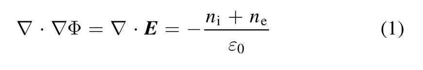
where Φ is the potential, E is the electric field,niandneare the ion charge density and electron charge density, and ε0is the dielectric constant of the vacuum.Note that in the region between the emitter and the grid,ne= 0; while the electron density downstream of grid is obtained by
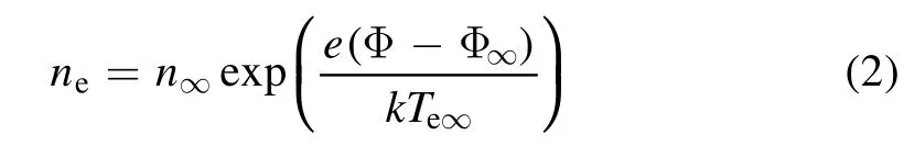
wheren∞is the ion density downstream of ion optics,eis the elementary charge quantity,kis the Boltzmann constant, Φ∞is the plasma potential downstream of ion optics, andTe∞is the temperature of the electron downstream of ion optics.
Then, the force of the ion withqin the electromagnetic field can be obtained from equation (3),
where F is the electric field force,andqis the charge quantity of ions.
In our model, the immersed finite element (IFE) method[14–17] is used to solve the electric field.The IFE method developed in recent years is a promising numerical tool for solving isotropic/anisotropic Poisson equations in structured meshes.The IFE method uses the slice basis function technique in the element divided by the interface,so that the mesh division does not depend on the interface.The other elements,which are not divided by the interface, use the traditional finite element basis functions.Therefore, the IFE method can effectively solve electromagnetic fields with complex boundary conditions in structured meshes.Moreover, compared with the traditional finite element method, the IFE method has few changes, so it is easy to program.
After obtaining the electric field, the motion of ions can be solved by Newton’s second law,
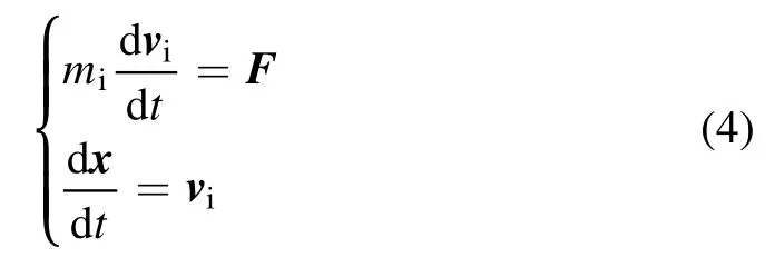
wheremiis the ion mass,viis the velocity of ions,and x is the position of ions.Then, equation (4) is solved by Boris’s leapfrog method [18].
2.2.Charge exchange collision
The low-speed CEX ions accelerate under the high voltage of the grid system, and some of them will bombard the surface of the grid, causing erosion.Assuming that the neutral atoms are uniformly distributed in the calculation area and obey the law of ideal gas, the number density of neutral atoms can be obtained from equation (5) [19],
wherennis the atom density,Iiis the beam currents, η is the ratio of atom to ion flow rate,vnis the atom velocity,andAsis the outlet area of atoms.In the region between the emitter and the grid,Asis the area of the grid slot.In the region downstream of the grid,Asis the exit of the calculation region.
Since the velocity of ions is much higher than that of atoms,in the calculation,the relative velocity between ions and atoms is replaced by the velocity of ions.The cross-sectionsσT(vi) of CEX collisions between atoms and ions is obtained as follows.

wherek1andk2are the collision section coefficients,k1=−1.492×10⁻¹⁰s andk2=2.6997×10⁻⁹m [19],viis the mode of ion velocity,andσT(vi)is the cross-section of CEX collisions.The collision frequencyμiis calculated by eq u ation (7),
wherenn(xi) is the atom density atxi.Then the collision probabilityPican be calculated according to equation (8),

whereΔtis the time step, andPiis the collision probability.
The null collision technique is used to deal with the particle collision in the Monte Carlo method [19].First, the maximum collision frequencyμmof all ions is calculated,

whereμmis the maximum collision frequency of all ions.
Then the maximum value of the collision probabilityPnullcan be obtained by using the maximum value of the collision frequency,

wherePnullis the maximum value of the collision probability.
The total number of ions in the calculation domain is expressed byNtot,and the collision frequencies μ of all ions in one step can be calculated by randomly selectingNtotPnullions.Selecting a random numberRbetween 0 and 1, ifμ μm>R,the collision occurs.
2.3.Grid erosion
The number of atoms bombarded by an ion from the material surface is called the sputtering yield,which is expressed byY.The sputtering yield is related to the energy of ion bombardment on the material, the angle between the impact trajectory and the normal of the material surface, and the physical properties of the material atoms.The erosion depth per unit time of a point on the grid surface impacted by incident ions is called the erosion rate,which is expressed byRE.The erosion depth of the grid can be obtained by multiplying the erosion rate by the working time.On a small areaS, it is assumed that ions uniformly bombard the surface of the grid.Assuming thatNions with unit charge bombard the small areaSin unit time, the current density formed on the grid surface can be calculated by equation (11),
whereJis the current density,Sis a small area, andNis the number of ions impactingS.According to the definition of sputtering yield, the number of atoms bombarded by the incident ions in the areaSper unit time can be obtained from equation (12),
whereNais the number of the bombarded atoms,andYis the sputtering yield.
If the mass of the material bombarded from the grid is expressed asM,the volumeVof the material can be obtained from equation (13),
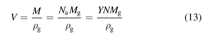
whereVis the volume of the whole bombarded atoms,ρgis the density of the gird material, andMgis the atom mass of the gird material.In this way, we can get the following expression according to the definition of erosion rate,
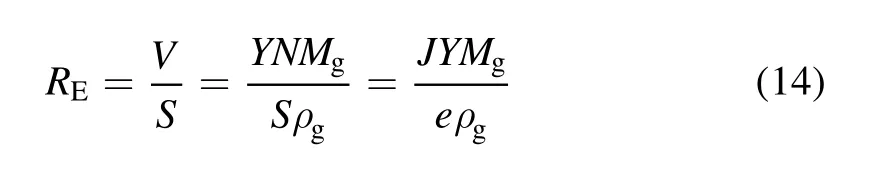
whereREis the erosion rate.
2.4.Sputtering yield
The grid material is molybdenum.According to the experimental data of molybdenum, the formula of sputtering yieldYis [20],
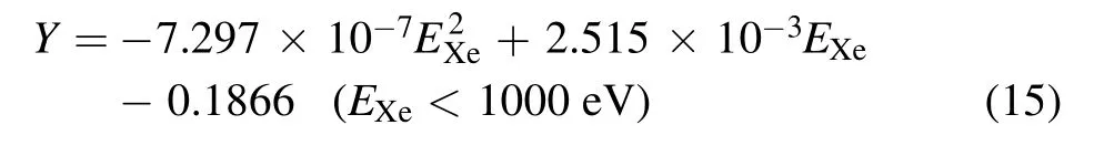
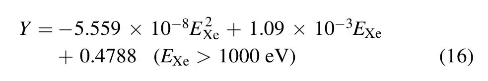
whereEXeis the ion impact energy, and
The sputtering yield is not only affected by the incident energy, but also related to the incident angleθi,hence
whenθi≤0.689,equation (18) is used to correctY,

whenθi> 0.689,equation (19) is used to correctY,
2.5.Parameter setting
The working medium is indium.The relative atomic mass of indium is 114.5, which is about 1.91×10⁻²⁵kg.The radius of the emitter tip is about 10 μm and the length of the emitter extending into the simulation domain is 0.05 mm.The emission current of the emitter is 100 μA.The ratio η is 2:3.In the region between the emitter and the grid,Asis about 1.04 mm2,while in the region downstream of the grid,Asis about 3 mm2.The velocity of the atom is set to 1000 ms–1.In our simulation,the neutral atoms are assumed to be uniformly distributed[19, 21]; hence the atom density is set to be 1.6×10¹⁸m−3between the emitter and the grid and 5.5×10¹⁷m−3downstream of the grid,according to the atom flow rate.The emitter voltage is set to 6 kV,and the grid voltage is set to −8 kV.The input parameters of the grid geometry are shown in table 1.

Table 1.Parameters of the FEEP grid model (normalized).
As shown in figure 1, the simulation model is simplified as a 60×20×50 cuboid with a mesh size of 0.05 mm.As for the field boundary condition,the surface withZ=Zmaxis set as the Dirichlet boundary,and the potential value is equal to 0, while the other surfaces are set as zero Newman boundary condition.As for the particle boundary conditions,theZ=ZminandZ=Zmaxsurfaces are set as absorption boundaries,while the others are set as symmetric boundaries.In addition, when the ion hits the grid, it is considered to be absorbed by the grid, so the ion is deleted in the simulation.
Finally, the simulation results in this paper are all normalized,and the reference parameters can be found in reference[22].
3.Simulation results and analysis
Figures 2–4 show the potential, ion and CEX ion density distributions, respectively.Because the distance between the grid and the emitter is very close,a large potential gradient is formed,while the potential gradient downstream of the grid is relatively small, and the equipotential surface is basically parallel to the grid.Hence, between the grid and the emitter,the beam ions will be accelerated by the strong electric field.While,in the downstream of the grid,the beam ion is mainly affected by the vertical downward electric field, which will cause the gradually increase of the beam divergence angle.
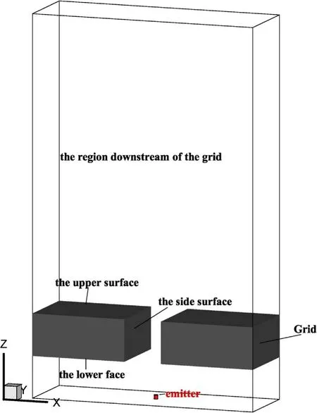
Figure 1.The geometry model of the FEEP grid.
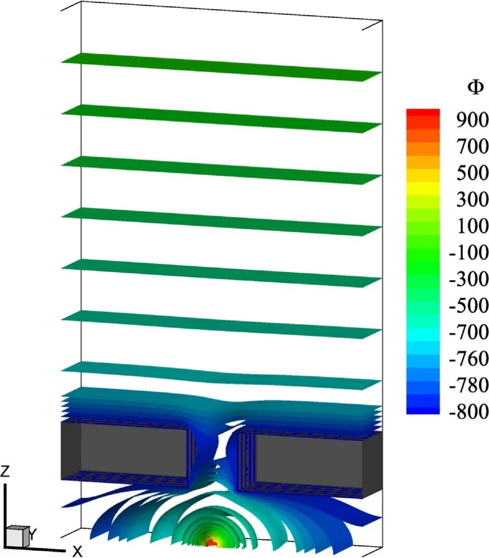
Figure 2.Potential distribution.
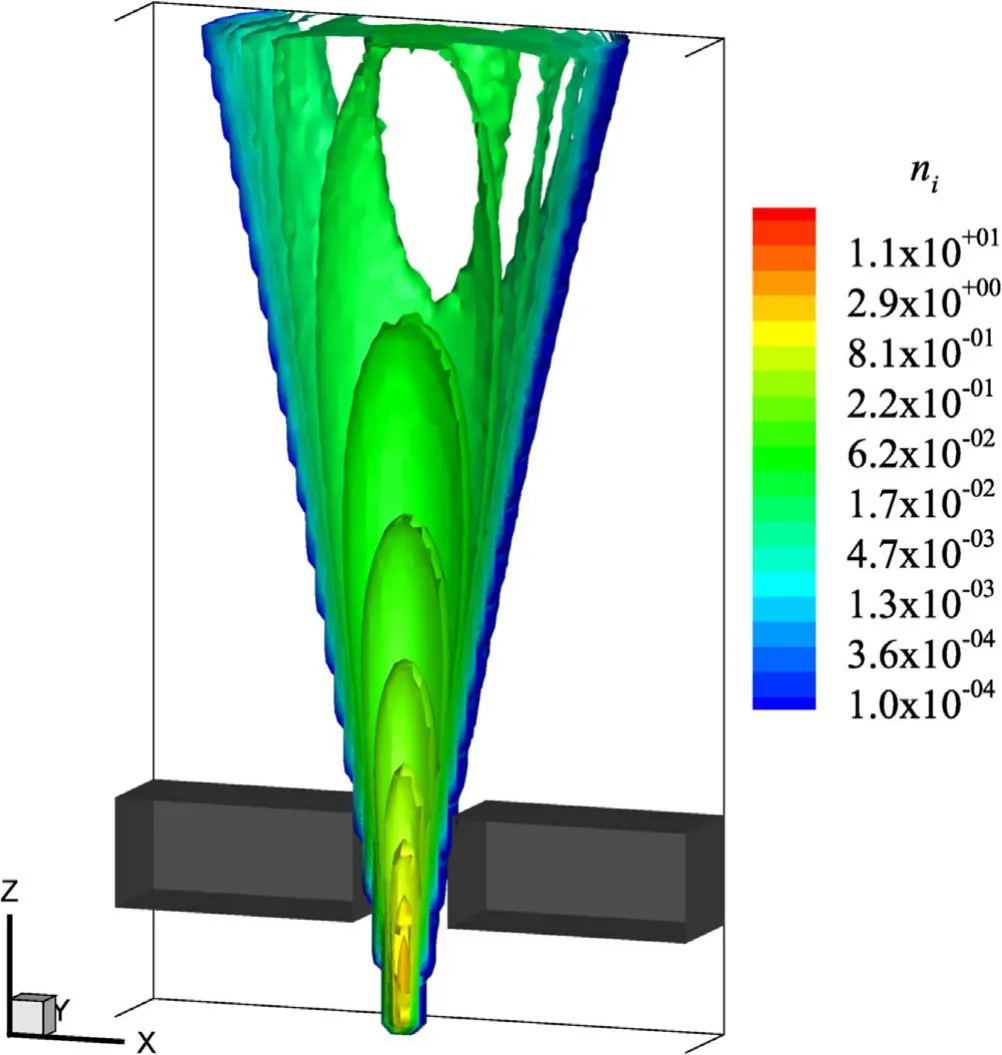
Figure 3.Beam ion density distribution.
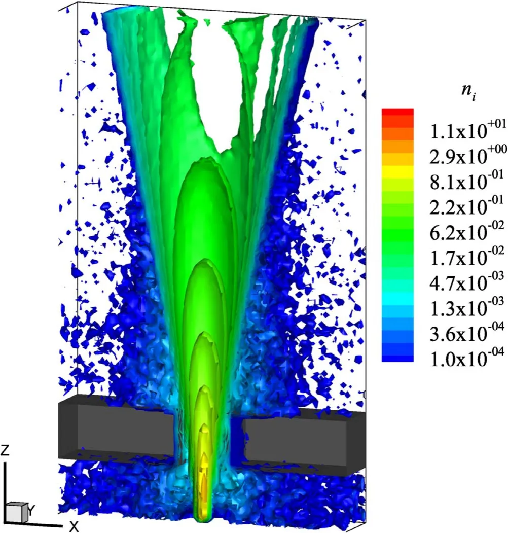
Figure 4.Density distribution of beam ions and CEX ions.
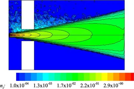
Figure 5.Comparison of density distribution between beam ion and CEX ion.
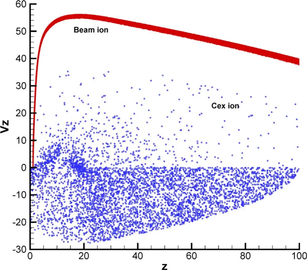
Figure 6.Velocity phase distribution of beam ions and CEX ions.
In figure 4, the green to red parts are mainly beam ions,and the blue parts are mainly CEX ions.From the density distribution of beam ions and CEX ions, it can be seen that the beam ions can be extracted and accelerated well, and no beam ions impinge directly on the grid.However, the distribution of CEX ions is relatively wide, with a large number of CEX ions impacting the grid slot and the end faces.
The density distributions of beam ions and CEX ions are compared in figure 5.In order to show the difference between the distribution of CEX ions and beam ions,the upper part of figure 5 contains both CEX ions and beam ions, while the lower part contains only beam ions.CEX ions are mainly concentrated near the grid.This is mainly due to the high velocity and high density of ions near the grid,which leads to obvious CEX collisions.However, in the downstream of the grid,the ion velocity and density decrease significantly so that the probability of CEX collision decreases.
Figure 6 shows the velocity phase distribution comparison of beam ions and CEX ions.Consistent with the analysis in figure 1, the beam ions undergo a rapid acceleration process and then slow deceleration, but the velocity of the beam ions is always along the positive direction of thez-axis.However,the velocity of most CEX ions is along the negative direction of thez-axis, which indicates that most CEX ions will return to the grid and cause grid erosion.
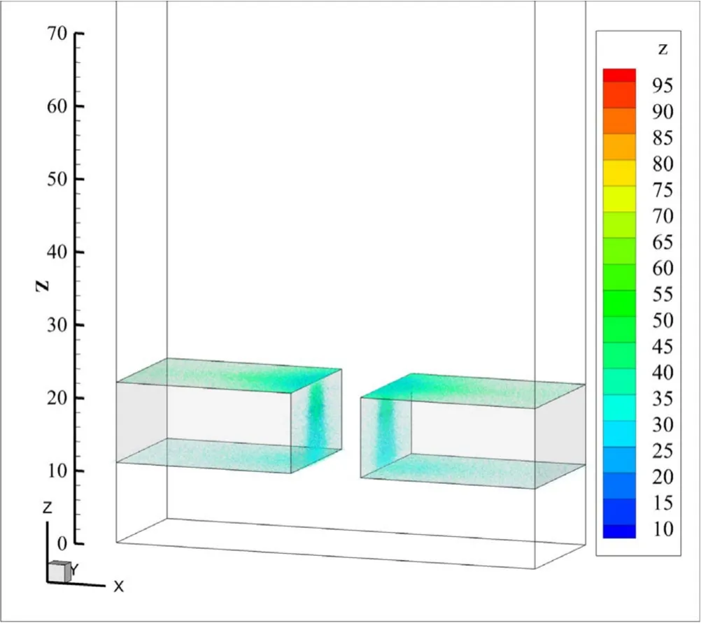
Figure 7.Distribution of CEX ions, which cause the grid erosion.
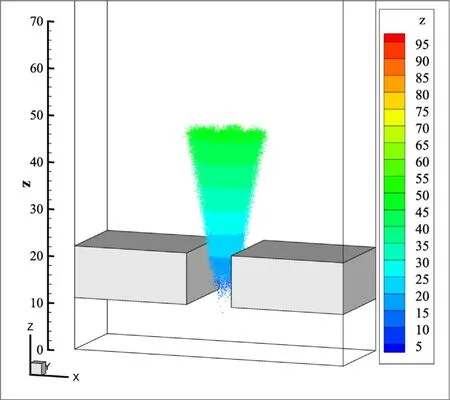
Figure 8.Location distribution of CEX ions causing grid erosion.
Figures 7 and 8 show the distribution of CEX ions,which cause the grid erosion, and their generation positions.In figures 7 and 8, thez-coordinate means the generation positions of CEX ions on thez-axis.It can be seen that these CEX ions mainly come from the position betweenz=20–70.This is consistent with the CEX ion distribution shown in figures 5 and 6.That is, the CEX ions causing the grid erosion are mainly generated between the grid and the emitter, and near the downstream of the grid.
Figures 9–12 show the CEX ion angle, energy, current density and erosion rate distribution of the upper surface,respectively.It can be seen that their impact angles on the upper surface is large, which is basically between 80° and 90°.The impact energy is about 1000 eV.The current density distribution shows that CEX ions are mainly concentrated near the grid notch.Due to the relatively small impact angle near the notch, the final erosion rate distribution on the upper face is relatively uniform, which is concentrated at 3.9×10⁻⁴m/1000 h.
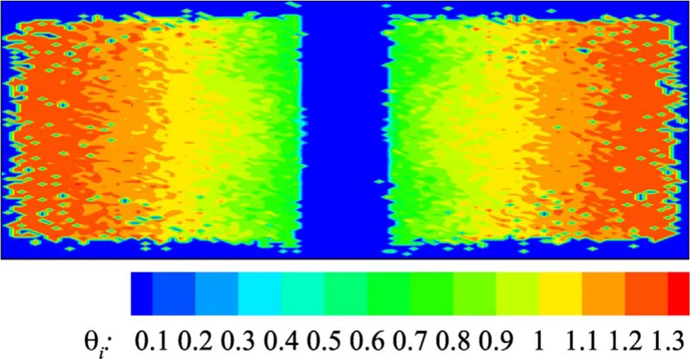
Figure 9.Impact angular distribution of the CEX ions impacting the upper surface.
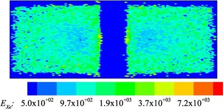
Figure 10.Energy distribution of the CEX ions impacting the upper surface.
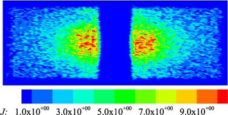
Figure 11.Current density distribution of the CEX ions impacting the upper surface.
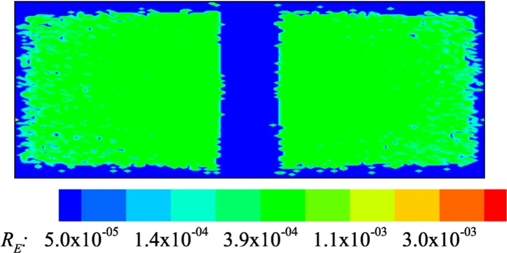
Figure 12.Erosion rate distribution of the upper surface.
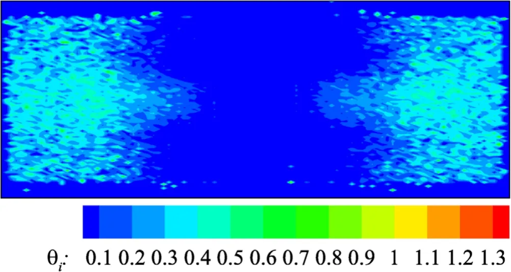
Figure 13.Impact angular distribution of the CEX ions impacting the lower surface.
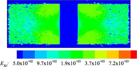
Figure 14.Energy distribution of the CEX ions impacting the lower surface.
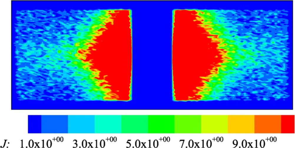
Figure 15.Current density distribution of the CEX ions impacting the lower surface.
Figures 13–16 show the CEX ion angle, energy, current density and erosion rate distribution of the lower surface.Comparing with figures 8–11,it can be seen that the CEX ion angle of the lower surface is very small, which is basically between 10° and 50°.This is because these CEX ions will first backflow from the downstream of the grid into the grid slot, then be rebounded by the emitter’s extremely high potential, and finally impinge on the lower surface.Meanwhile,because of the obvious radial electric field between the grid and the emitter, the impact angle of these CEX ions on the lower surface is very small.However,their impact energy is relatively high, about 2000 eV, and the current density distribution shows that CEX ions are also concentrated near the grid notch.Due to the small impact angle,the erosion rate distribution of the lower surface is similar to that of the upper surface, which is about 3.9×10⁻⁴m/1000 h.
Figures 17–20 show the CEX ion angle, energy, current density and erosion rate distribution on the side surface of the notch.It can be seen that the CEX ion angle on the side surface is also large,which is basically between 70°and 90°.However, the impact energy of these CEX ions is relatively low, about 600 eV.The current density distribution shows that the CEX ions on the side surface are concentrated in the middle of the notch.Because of the large impact angle, the erosion rate distribution on the side surface of notch is also about 3.9×10⁻⁴m/1000 h.
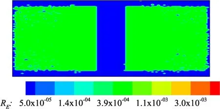
Figure 16.Erosion rate distribution of the lower surface.
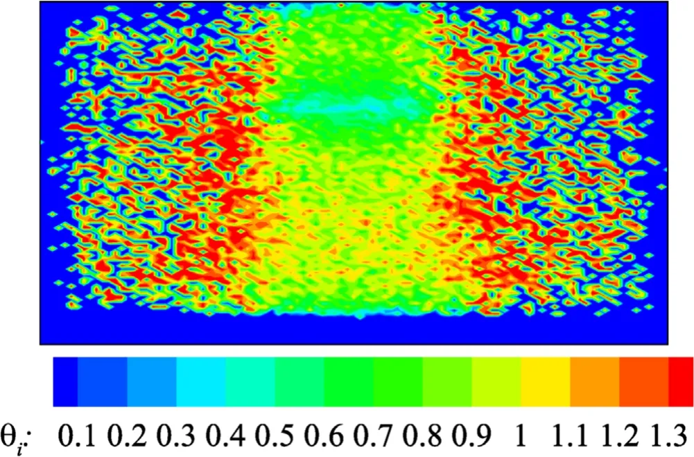
Figure 17.Impact angular distribution of the CEX ions impacting the side surface.
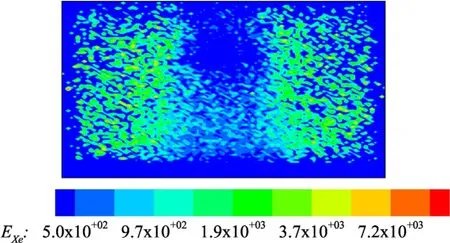
Figure 18.Energy distribution of the CEX ions impacting the side surface.
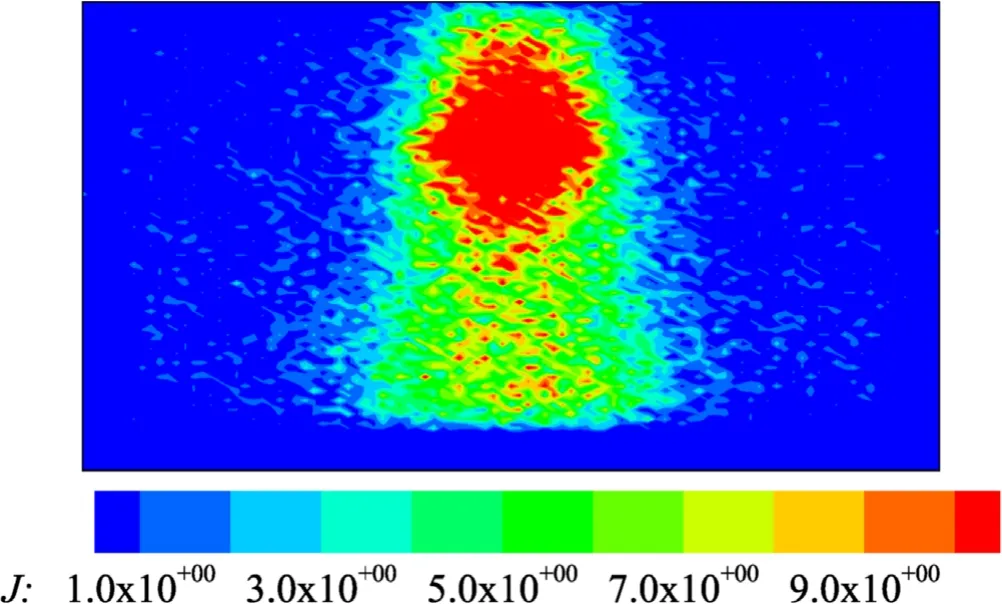
Figure 19.Current density distribution of the CEX ions impacting the side surface.
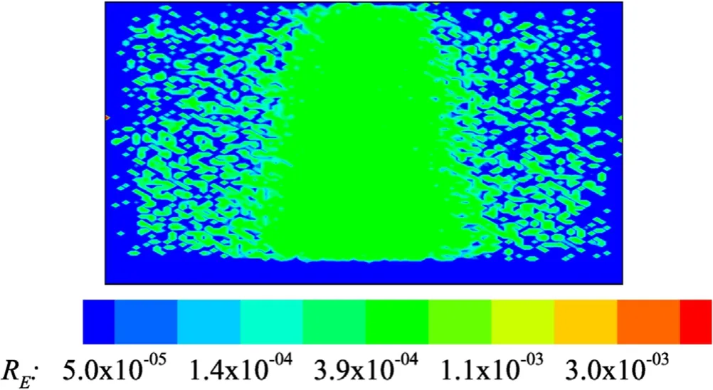
Figure 20.Erosion rate distribution of the side surface.
In summary, the grid erosion is mainly caused by the returned CEX ions.These CEX ions are mainly generated betweenz=20–70, that is, near the grid.These CEX ions return to the upper surface, lower surface and notch side surface of the grid under the influence of the grid negative potential.The impact angle of these CEX ions returning to the upper and side surfaces is large (about 70°–90°), but their energy is low(about 600–1000 eV),while the impact angle of CEX ions returning to the lower surface is very small (about 10°–50°),but their energy is high(about 2000 eV).The above characteristics lead to the similar erosion rates of these three surfaces (about 3.9×10⁻⁴m/1000 h).
4.Conclusion
In this paper, the three-dimensional simulation model for the FEEP grid is established by the IFE-PIC-MCC method.The erosion mechanism of the FEEP grid was analyzed by this model.The simulation results show that the grid erosion is mainly caused by the returned CEX ions,while the beam ions make little contribution to the grid erosion.The velocity and density of the beam ions near the grid are high, so the CEX collision frequency near the grid is high, leading to CEX ions mainly generated near the grid.Some of these CEX ions return to the upper surface,lower surface and notch side surface of the grid.The impact angle of CEX ions returning to the upper and side surfaces is large,but their energy is low,while the impact angle of CEX ions returning to the lower surface is small,but their energy is high.The above characteristics lead to the similar erosion rates of these three surfaces.
Acknowledgments
This work was supported by National Natural Science Foundation of China (No.11675040), the Fundamental Research Funds for the Central Universities of China (Nos.DUT20LAB203 and DUT21GJ206), the Key Research and Development Project of Liaoning Province (No.2020JH2/10500003), and the Open Fund for Tianqin Project Key Laboratory of Ministry of Education(in preparation)(TQRF-2020-2.5).
猜你喜欢
作文新天地(小学版)(2022年5期)2022-05-31
数学大王·趣味逻辑(2020年9期)2020-09-06
青年文学家(2020年16期)2020-07-13
参花(下)(2020年4期)2020-04-16
小学生作文辅导·读写双赢(2017年10期)2018-02-21
天津诗人(2017年2期)2017-11-29
课程教育研究·新教师教学(2017年8期)2017-10-31
读者·原创版(2015年5期)2015-11-14
新青年(2014年5期)2014-05-27
青年文摘·上半月(1995年9期)1995-01-01
 Plasma Science and Technology2021年10期
- Plasma Science and Technology的其它文章
- Investigation of variable aperture on the performance and lifetime of ion thruster
- Experimental study of a porous electrospray thruster with different number of emitterstrips
- Design and fabrication of a full elastic submicron-Newton scale thrust measurement system for plasma micro thrusters
- A plasma equilibrium model for rapid estimation of SF-MPDT performance
- Numerical simulation of the effects of protrusion on DC arc anode attachment
- The ablation characteristics of laser-assisted pulsed plasma thruster with metal propellant