
Angular dependence of vertical force and torque when magnetic dipole moves vertically above flat high-temperature superconductor∗
2021-12-22 06:50YongYang杨勇ShuaiJieYang杨帅杰WenLiYang杨文莉andYunYiWu吴云翼
Chinese Physics B 2021年12期
关键词:杨勇
Yong Yang(杨勇) Shuai-Jie Yang(杨帅杰) Wen-Li Yang(杨文莉) and Yun-Yi Wu(吴云翼)
1School of Mechano-Electronic Engineering,Xidian University,Xi’an 710071,China
2Shaanxi Key Laboratory of Space Extreme Detection,Xi’an 710071,China
3China Three Gorges Science and Technology Research Institute,Beijing 100036,China
4Physikalisches Institut B,RWTH Aachen,Aachen 52056,Germany
Keywords: high-temperature superconductor,magnetic dipole,frozen-image model,angle
1. Introduction
The passive levitation between bulk high-temperature superconductors (HTSs) and permanent magnets (PMs) can simultaneously provide the stability in different directions due to the strong flux pinning characteristic of HTS.Since the discovery of HTS in 1986,the HTS levitation has been successfully applied to many practical engineering aspects, such as the superconducting magnetic levitation vehicles[1–3]and the bearings for flywheel energy storage system.[4–6]At the same time, a large number of studies have been performed to improve the levitation performances including vertical force,lateral force,magnetic stiffness,etc.[7–13]In addition,it has been found experimentally that the angle between the magnetization direction of the PM and thecaxis of the HTS significantly affects the levitation properties.[14–18]In fact, the magnetization direction of the PM does not often coincide with thecaxis of the HTS in many practical applications.
More than 20 years ago, Shiet al.[14]and Tentet al.[15]experimentally investigated that the domain orientation affects the levitation force for the cubic and spherical geometries of the HTS samples, respectively. They found that the levitation force varies in a cosine law fashion with the angle between the direction of the magnetic field and thecaxis of the HTS. Also, Yanget al.measured the levitation forces of the YBCO bulk samples with different grain-orientations at liquid nitrogen temperature.[16,17]It is found that the levitation force decreases monotonically with the angle between thecaxis and the normal to the polished surface. A simple formula was proposed to describe the relationship between the levitation force and the angle for a relatively low external magnetic field produced by a PM.[17]Very recently, the effect of magnetization angle on the levitation force of the bulk HTS was studied in high magnetic field produced by a superconducting magnet.[18]It was also shown that the levitation force decreases with increasing angle between the upper surface of the bulk HTS and the horizontal plane. In addition, the experimental results[18]indicated that the relationship between the angle and the levitation force of the bulk HTS is complex and cannot be expressed by using Yang’s formula[17]in high magnetic field.
In the studies of modelling superconducting magnetic levitation, many different numerical and analytical approaches, such as the models of solving differential Maxwell equations combining different relations between the electric field and the current density in superconductor,[19–25]the method based on the minimization of the magnetic energy[26,27]and the models based on the calculation of magnetic moments,[28–37]have been proposed. A very complete and comprehensive compilation for modelling magnetic levitation can be found in a recent review paper.[38]In the aforementioned calculation models, the image models of the magnetic diploe have been widely used to design and optimize the superconducting magnetic levitation systems because the models can give the simple and analytical expressions of force,torque, and stiffness and need a very shorter calculation time than the complicated numerical simulation models, such as the finite element method combining the critical state models. The simplest form of the magnetic image model was used to calculate and describe the levitation behavior for a magnetic dipole over a semi-infinite superconducting plane in the Meissner state.[30,31]In this case, the magnetic dipole has only one image named the diamagnetic mirror image below the superconductor top surface. The lateral position of the diamagnetic mirror image is the same as that of the magnetic dipole, and the vertical height below the superconductor surface equals the height of the magnetic dipole above the surface. The simplest form of the image model can describe only the HTS magnetic levitation properties in the zero field cooling(ZFC)case. Kordyuk[32]added a frozen image,which creates the same magnetic field distribution outside the superconductor as the frozen magnetic flux, into the image model to study the field cooling (FC) state of the bulk HTS. Then Hull and Cansiz[33]used the frozen-image model to calculate the vertical force, lateral force, and stiffness, and found the calculations to be in good agreement with their measurements when they used the equivalent current loops in the axisymmetric case to calculate the vertical force. But the frozen-image model did not predict hysteresis in the vertical force or lateral force and could not give the lateral force in ZFC either,because the frozen-image model did not take into account the flux flow as the PM moved. To remedy these problems,Yang and Zheng have proposed introducing two additional magnetic dipoles they called the vertical and horizontal movement images respectively, to consider the magnetic flux changes due to the vertical and lateral motions of the PM.[34]Subsequently Zhanget al.amended the location of the vertical movement image below the HTS surface to obtain the relationship between the maximum levitation forces and the initial cooling heights.[35]In addition,Wuet al.[36]modified the change rules of the vertical movement image in the advanced frozen-image model proposed by Yang and Zheng[34]to describe the hysteresis loops in the second and subsequent descent–ascent cycles of the PM.
The above theoretical investigations using the magnetic image models do not contain the influence of the angle between the magnetization direction of the PM and thecaxis of the bulk HTS on the levitation behavior. The angular dependence of forces has been calculated using the dipole–dipole image model between a small PM and a superconductor in the Meissner state.[39–45]The results showed that the levitation force is maximum when the magnetic moment is perpendicular to the surface and minimum when it is parallel,[39]which is at least in a qualitative agreement with the measured data.[17]Coffey studied the levitation force between a magnetic dipole and a superconducting sphere in the perfect flux exclusion state for two different orientations of the dipole,vertically and horizontally.[40,41]The magnetic force and torque on a superconducting sphere in an arbitrary orientation of the magnetic dipole also were calculated in the Meissner state.[42–45]In addition,the frozen-image model has also been employed to calculate the interaction between a small magnet and an HTS in FC for an arbitrary orientation of the dipole. Alqadiet al.analyzed the angular dependence of the levitation force and energy by utilizing the frozen-image model for a system composed of a small magnet and a superconducting sphere.[46]Using the same model,Sivrioglu and Cinar,[47]Sivrioglu and Basaran,[48]and Basaran and Sivrioglu[49]studied the magnetic potentials and stiffness values for the practical ringshaped PM–HTS bearings with the variation of the angle between the rotational magnetization symmetry axis of the PM and the levitation direction. Although the interaction between the PM and the HTS with angle has been studied by using the image or frozen-image model in the literature,the angular dependence of force and torque has not yet been investigated so far by utilizing the advanced frozen-image model, which can consider the flux change due to the motion of the PM.Moreover, the torque between a superconductor and a magnet has been seldom studied and was reported only for the Meissner state.[44,45]
In this paper, the PM–HTS levitation system is simplified into a magnetic dipole levitated above the semi-infinite flat HTS.Based on the magnetic field distribution of the magnetic dipole directing to an arbitrary direction, the levitation force and torque on the PM are calculated by using the advanced frozen-image model with an arbitrary angle between the magnetization direction of the PM and thecaxis of the semi-infinite flat HTS. The variations of the levitation force and torque with the angle are obtained as the PM moves vertically above the HTS. The rest of this paper is structured as follows. In Section 2,we describe the advanced frozen-image model for the vertical motions of the PM with arbitrary angle in the ZFC condition and the FC condition,and derive the generally analytical expressions of the magnetic field, force and torque. In Section 3, the results of the levitation force and torque under different angles are presented and discussed in the ZFC condition and the FC condition as the PM moves vertically. Finally,the conclusions are drawn in Section 4.
2. Calculation model for force and torque
Figure 1 shows a schematic diagram of the calculation model. The PM is simplified as a magnetic dipole with the magnetic momentm1, has an angleθwith respect to thezaxis. The bulk HTS is assumed to have a semi-infinite structure. The origin of rectangular Cartesian coordinate system is taken at the center of the bulk HTS surface.Based on the magnetic image method in the electrodynamics and the advanced frozen-image model,[34]the diamagnetic imagem2having an angle ofπ–θmoves as the PM moves. The frozen imagem3having an angle of−θdoes not moves and has a fixed position below the HTS surface. The vertical movement imagem4having an angle ofπ–θin ZFC or an angle of−θin FC also has a fixed position. According to previous studies,[33,34]the vector moduli ofm1,m2, andm3have the same value,however, the modulus ofm4changes as the PM vertically moves. The images ofm3andm4have the stationary positions(0,−h)and(0,−z0),respectively,wherehis the initial cooling height andz0is the minimum vertical gap between the PM and the HTS surface. The image ofm2has a changing position(0,−z)as the PM vertically moves.

Fig. 1. Schematic diagram of advanced frozen-image model with arbitrary angle θ between the magnetization direction of the PM and the c axis of the HTS under(a)ZFC and(b)FC,with 1–4 representing PM,diamagnetic image,frozen image,and vertical movement image,respectively,h being initial cooling height, z0 and zm denoting minimum and maximum vertical gaps between the PM and the HTS surfaces,respectively,h bing equal to z0 in FC.
From magnetomechanics, the force and torque between two magnetic dipoles can be given as
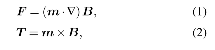
wheremrefers to the magnetic moment of one dipole,Bdenotes the magnetic field from the other dipole, andFandTare the force and torque vectors,respectively.
The magnetic field produced by a magnetic dipole having an angleθwith respect to thezaxis can be derived from the Biot–Savart’s law and the superposition principle. As shown in Fig.2,the dipole with the magnetic momentmcan be considered as a small current loop with radiusRand currentI.The magnetic momentmof the dipole withθis decomposed intomzin thez-axis direction andmxin thex-axis direction.Using the Biot–Savart’s law, the expressions of the magnetic field at any location pointM(x,y,z) produced by the vertical componentmzand the lateral componentmxof the magnetic dipole can be obtained as follows:

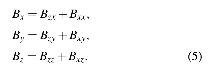
whereµ0is the permeability of vacuum,the first subscript and the second subscript of the magnetic field components indicate the component of the magnetic moment and the direction of the magnetic field,respectively. Each component of the total magnetic field can be obtained by the superposition of the corresponding components in Eqs.(3)and(4). Therefore,the expressions of the total magnetic field can be given as
When the PM moves only vertically along thez-axis direction,according to the superposition principle and Eqs.(1)and(2),the forces and torques acting on the magnetic dipolem1at coordinate(0,z)due to the diamagnetic dipolem2at(0,−z),the frozen dipolem3at(0,−h)and the vertical movement dipolem4at(0,−z0)are

wherem1,m2,m3,andm4are the vector modulus ofm1,m2,m3, andm4, respectively. From Eqs. (6) and (7), the interactions between the PM with angleθand the HTS include not only the levitation forceFz, but also the torqueTy, which is distinguished from the interaction between the PM without angle and the HTS. In the practical applications of the HTS levitation systems,the levitation body usually undergoes some disturbances, which may make the body tilt. The torqueTyemerges according to Eq.(7)because the angleθis not equal to zero. The torque can make the levitation body rotate about theyaxis and determines the rotation stability of the levitation body.
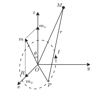
Fig.2.Schematic diagram for calculating magnetic field at any location point M(x,y,z)produced by dipole with magnetic moment m having angle θ with respect to the z axis,dipole being considered as a small current loop(the dotted circle)with radius R and current I,and mx and mz denoting components of m along the x and z directions,respectively.
3. Results and discussion
In the study,the variation rule ofm4is the same as that in the advanced frozen-image model.[34]We adopt the following parameters:m1=m2=m3=5.0×10⁻³A·m2,z0=0.5 mm,a1= 0.1 A·m,a2= 5.0 A·m,b1= 5.0×10⁻²A·m, andb2=0.15 A·m, wherea1,a2,b1, andb2are the proportional constants ofm4for different initial cooling conditions and different vertical movement processes of the PM. The values of initial cooling heighthare taken as 30 mm in ZFC and 0.5 mm in FC,respectively. The values of above parameters are identical to those counterparts in a previous paper[34]in order to compare the calculation results with the published ones.
3.1. ZFC case
As the PM firstly descends from the initial cooling positionz=h=30 mm to the lowest positionz=z0,the direction of the vertical movement image (m4) keeps the same as that of the diamagnetic image(m2)in ZFC because the magnetization of the bulk HTS is diamagnetic(Fig.1(a)). In the PM descending and ascending processes, the values of the vertical movement image can be obtained by the rules ofm4under ZFC through using the proportional constants ofa1anda2in the advanced frozen-image model.[34]Figure 3 shows the curves of typical levitation force with different angles in ZFC.At each vertical gap,the repulsive vertical force generally decreases as the angle increases from 0 toπ/2, which qualitatively accord with the curves of measured levitation force with different values ofθ.[17]Moreover, the area of the hysteresis cycle also decreases withθincreasing. As the angle of the PM increases,the magnetic field that the bulk HTS feels may decrease though the relative location of the PM never changes.This leads to the fact that the levitation force and the area of the hysteresis cycle decrease. The inset of Fig.3 displays the effect ofθon the maximum value of the levitation force. It is obvious that the maximum vertical repulsive force changes as a cosine law fashion when the angle increases from 0 to 2π, which is also in agreement with the experimental result reported by Tentet al.[15]The cycle of the cosine law isπ.Although the calculation results of vertical force in the present paper are consistent qualitatively with the previous experimental data,[15,17]the advanced frozen-image model with arbitrary angleθcannot give the quantitative calculations either, because the model does not contain the size effect of the HTS levitation system. However, the model should give the quantitative results including the size effect of the superconducting levitation system if the PM and its images are replaced by Amperian current loops.
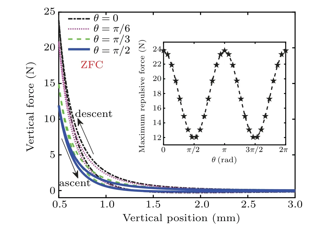
Fig.3. Curves of levitation force versus levitation height at different angles θ =0,π/6,π/3,and π/2 in ZFC,with inset showing relationship between maximum vertical repulsive force and angle changing from 0 to 2π.
Figure 4 shows the variations of torqueTywith vertical height at different angles in ZFC when the PM vertically descends and ascends.The torque on the PM appears if the angle is not equal to zero and increases as the angle increases from 0 toπ/4. The magnetic hysteresis effect can also be found from the curve of the torqueversusvertical gap according to the calculations. The torqueTydecreases as the vertical gap between the PM and the HTS increases. The maximum value ofTyis gained at the lowest position for any value ofθ. The inset of Fig. 4 displays that the maximum value ofTyvaries with angleθfrom 0 to 2π. As can be seen from Fig.4 and its inset, the value ofTyis positive asθchanges from 0 toπ/2 in ZFC. The torqueTywith the positive value tends to align the PM parallelly to the HTS surface if the orientation of the PM magnetization deviates from thezaxis. From the viewpoint of the rotational equilibrium,θ=0 is thereby deemed to be an unstable equilibrium point in ZFC,which accords with the result of the torque between a superconductor sphere in the Meissner state and a finite-size PM reported by Diez–Jimenezet al.[45]The maximumTychanges as a sine law fashion when the angle increases from 0 to 2π, which means that the characteristic of theθ-dependentTyis different from that of theθ-dependent levitation force for the same cooling condition.The cycle of the sine law isπ. At any vertical position, the torque is maximum atθ=π/4+nπ/2, wherenis any arbitrary integer. In addition, the toqueTyis equal to zero as the magnetization direction of the PM is perpendicular or parallel to thea–bplane of the HTS bulk.
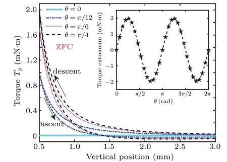
Fig.4.Variations of torque Ty with levitation height at different angles θ =0,π/12,π/6,and π/4 in ZFC,with inset showing relationship between maximum torque and angle varying from 0 to 2π.
3.2. FC case
When the PM ascends from the initial cooling positionz=hto the highest positionz=zm, the orientation ofm4is considered as that of the frozen imagem3in FC because the magnetization of the bulk HTS is paramagnetic (Fig. 1(b)).The values of the vertical movement image can be obtained by the rules ofm4under FC using the proportional constants ofb1andb2in the advanced frozen-image model.[34]Figure 5 shows the relationship between the vertical force and the vertical height at different angles in FC.At each vertical position,no matter whether the process of the PM is ascent or descent,the attractive or repulsive force generally decreases as the angle increases from 0 toπ/2. In addition,the magnetic hysteresis effect is always remarkable for different values ofθ,which may be caused by a large quantity of the frozen fluxes in FC.The inset of Fig.5 displays theθ-dependent maximum vertical repulsive and attractive forces. It is obvious that the maximum repulsive force changes in a cosine law fashion when the angle increases from 0 to 2π. However,the maximum attractive force varies with a negative cosine function because of the negative sign of the attractive force. Like the case in ZFC,the cycle of the positive cosine law and the negative cosine law are alsoπ.
It should be pointed out that the curves of vertical force withθ=0 in Figs.3 and 5 are identical to the corresponding curves in Fig.3 of Ref.[34]because all parameters are identical, which also attests to the calculations credible. Because the calculation results in the present paper are qualitative,the reliability of the calculations cannot be confirmed by quantitatively comparing with the experimental data. But our calculations qualitatively accord with the experimental[15,17,33]and theoretical[34,45]results.
Comparing Fig.3 with Fig.5,one can find that the maximum vertical repulsive force in ZFC is much larger than that in FC under the same angle. The reason is that the maximum vertical repulsive force is determined by the diamagnetic property of the HTS for a certain levitation system. In the ZFC,the HTS is dominated primarily by the diamagnetic property,while in the FC,the HTS is governed mainly by the flux pinning characteristic. Therefore,the levitation force usually appears much bigger in the ZFC than in the FC.Previous experimental results[33]withθ=0 also showed such a characteristic of the vertical force in different cooling conditions.

Fig. 5. Curves of vertical force versus vertical height at different angles θ =0, π/6, π/3, and π/2 in FC, with inset showing angular dependence of the maximum vertical repulsive and attractive forces.
Figure 6 shows the variations of the torqueTywith vertical height at different angles in FC when the PM vertically ascends and descends. At each vertical position, the absolute value ofTygenerally increases as the angle increases from 0 toπ/4. The inset of Fig.6 displays that the extreme value ofTychanges with angleθfrom 0 to 2πin FC.From Fig.6 and its inset, it follows that the torque on the PM has a negative value during ascent in FC as the angle varies from 0 toπ/2.The torqueTywith the negative value tends to rotate the PM to its original orientation if the direction of the PM magnetization deviates from thezaxis. Therefore,θ=0 is considered as a stable equilibrium point during ascent in the FC,which is distinguished from the unstable equilibrium point at the same angle in the ZFC.But the torqueTyhas positive value during descent at a small vertical gap because the diamagnetic property of the HTS is enhanced as the PM approaches to the HTS.The extreme value ofTychanges as a negative sine law fashion during ascent when the angle increases from 0 to 2π,however,the torque extremum varies with a positive sine function during descent. The cycle of the negative sine law and positive sine law are bothπ. Like the case in ZFC,at any vertical position,the torque obtains the extreme values atθ=π/4+nπ/2.
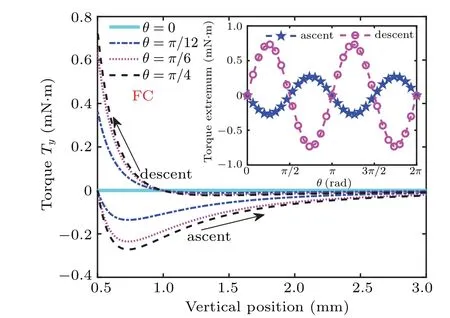
Fig.6.Variations of torque Ty with levitation height at different angles θ =0,π/12,π/6,and π/4 in FC,with inset showing angular dependence of torque extremum.
4. Conclusions
The vertical forceFzand rotational torqueTyare calculated by the advanced frozen-image model[34]when the PM vertically moves above the semi-infinite HTS.The PM has an angleθwith respect to thecaxis of the HTS. The torqueTyappears due to the non-zeroθ. Different results of the levitation forceFzand torqueTyfor the ZFC condition and the FC condition are summarized as follows.
(i)For both cooling conditions,the repulsive or attractive vertical force decreases withθincreasing from 0 toπ/2.
(ii) When increasingθ, the maximum repulsive vertical force changes as a positive cosine law fashion in ZFC and FC,however the maximum attractive force varies with a negative cosine law in FC.
(iii)For both cooling conditions,the absolute value ofTygenerally increases withθincreasing from 0 toπ/4.
(iv) From the viewpoint of the rotational equilibrium,θ=0 is thereby deemed to be an unstable equilibrium point in ZFC,however,θ=0 is considered as a stable equilibrium point in FC.
猜你喜欢
社会科学战线(2022年8期)2022-10-25
财会月刊·下半月(2022年4期)2022-04-25
湘潮(上半月)(2021年11期)2022-01-15
湘潮(2021年11期)2021-12-03
北广人物(2018年21期)2018-06-27
大学生(2016年19期)2016-11-25
军事历史(1997年5期)1997-08-21

- Chinese Physics B的其它文章
- Transient transition behaviors of fractional-order simplest chaotic circuit with bi-stable locally-active memristor and its ARM-based implementation
- Modeling and dynamics of double Hindmarsh–Rose neuron with memristor-based magnetic coupling and time delay∗
- Cascade discrete memristive maps for enhancing chaos∗
- A review on the design of ternary logic circuits∗
- Extended phase diagram of La1−xCaxMnO3 by interfacial engineering∗
- A double quantum dot defined by top gates in a single crystalline InSb nanosheet∗