
Fast-sweeping Langmuir probes:what happens to the I-V trace when sweeping frequency is higher than the ion plasma frequency?
2022-03-10 03:50ChenyaoJIN靳琛垚ChishungYIP叶孜崇WeiZHANG张炜DiJIANG江堤andGuoshengXU徐国盛
Plasma Science and Technology 2022年2期
Chenyao JIN(靳琛垚),Chi-shung YIP(叶孜崇),Wei ZHANG(张炜),Di JIANG(江堤)and Guosheng XU(徐国盛)
1 Institute of Plasma Physics,Hefei Institutes of Physical Science,Chinese Academy of Sciences,Hefei 230031,People’s Republic of China
2 University of Science and Technology of China,Hefei 230026,People’s Republic of China
Abstract Limited particle transit time is one of several limiting factors which determine the maximum temporal resolution of a Langmuir probe.In this work,we have revisited the known fast sweep Langmuir probe techniques in a uniform,quiescent multi-dipole confined hot cathode discharge with two operation scenarios:one in which the probe sweeping frequency fsweep is much lower than the ion plasma frequency fpi,another one where fsweep is much greater than fpi,respectively.This allows investigation into the effect of limited ion-motion on I-V traces.Serious distortions of I-V traces at high frequencies,previously claimed to be an ion-motion limitation effect,were not found unless shunt resistance is sufficiently high,despite a fsweep/fpi ratio of ~3.On the other hand,evidences of sheath capacitance on the I-V traces have been observed.Distortions of I-V traces qualitatively agree with predictions of sheath capacitance response to the sweeping voltage.Additionally,techniques in fast sweep Langmuir probe are briefly discussed.The comparison between the high-speed dual Langmuir probe(HDLP)and the single probe setup shows that the capacitive response can be removed via subtracting a leakage current for the single probe setup almost as effectively as using the HDLP setup,but the HDLP setup does remain advantageous in its facilitation of better recovery of weak current signal commonly in low density plasma.
Keywords:high speed diagnostics,time resolved diagnostics,Langmuir probe
1.Introduction
Langmuir probes are widely employed in fusion[1],plasma processing[2],electric propulsion[3]and other fields of plasma sciences.As turbulence-rich phenomena become gradually of interest,time-resolved measurements[2,4,5]become increasingly popular.This is usually realized by either fast-sweeping techniques[6]or so-called phase averaged measurements[7]via sweeping the Langmuir probe very slowly and measuring time-resolved current of each voltage step in controlled pulses or when the plasma processes are strongly repeatable[8,9].Fast sweeping techniques are preferred techniques in turbulent plasmas as well as pulsed plasmas where operational costs are expansive.With increasing interests in studying phenomena whose temporal period is often shorter than 1 ms,so as the demand for fast sweeping probes with sweeping frequenciesfsweep>100 kHz[7,10-14].
Generally,it is expected that if a probe sweeps much faster than the ion sheath transit time,typically the period of the ion plasma frequency 1/fpi,an equilibrium sheath cannot truly form and the collected current is,therefore,a timeaveraged current of a non-equilibrium sheath[7].Previous studies have reported distortion of theI-Vtrace due to ion motion effects even when the voltage sweep period is 8.5 times the ion transit time[14].This raises an important question:is it possible to use a fast-sweeping probe with a sweeping frequencyfsweepclose to or faster than the ion plasma frequencyfpito measure plasma parameters with reasonable accuracy? This work experimentally investigates the effects of circuitry and sheath formation whenfpi<fsweep≪fpeon theI-Vtraces of fast-sweeping,planar Langmuir probe with the known capacitance compensation technique.In this work,the probe radiusrprobeis much larger than the Debye length λDebye.This is done by performing measurements with varying sweeping frequencies from 500 Hz,with which effects of stray capacitance are negligible,to up to 500 kHz.The ion plasma frequency is also adjusted via changing the plasma density for thefsweepto cover a range betweenfpi≫fsweepandfpi<fsweep.
2.Ion mobility limited sheath formation in rapidly swept Langmuir probes
When a bias voltage is applied to a Langmuir probe,an ion sheath or an electron sheath forms depending on the probe biasVbiasrelative to the plasma potentialVp.When theVbiasis lower thanVp,electrons are repelled and only the ones with sufficient kinetic energy to overcome the potential barrier will be absorbed by the probe,while ions are attracted into the probe untilVbias>Vp,thus forming an electron sheath.Without considering fast voltage sweeping effects,the contribution of ion current to any region of theI-Vtrace below the plasma potential is expected to be the ion saturation current,and any additional ion current with more negative probe bias is expected to be effects of sheath expansion.On the other hand,the electron current is determined by the Boltzmann relation and maximum potential difference between the plasma and the probe,note that for almost all planar Langmuir probe theories,the resolution of the Boltzmann relation to predict the electron current does not involve the exact sheath structure near the probe,only an assumption of monotonically decreasing potential from the bulk plasma to the probe surface is necessary.Withfsweepapproachingfpi,ions are expected to be motion limited as the sheath structure rapidly changes withVbiasbefore they can transit through the sheath,causing reduction and possibly fluctuation of the ion saturation current.
However,the ion saturation current of a Langmuir probe in a low temperature plasma is expected to be very small compared to the electron saturation current due to the mass differences.In plasmas with only electrons and singly charged argon ions,for example,ion saturation current is expected to be on the order of(me/mi)1/2≈1/271th of the electron current.Thus any distortion by the fluctuating ion flow,of which magnitude is expected to be limited to the ion saturation current,would also be very small compared to even the exponential electron current.Note that the ion saturation current is the maximum ion current reachable to the probe determined by the local plasma density.Therefore,for fluctuations of the ion flow alone(without considering electron dynamics)to contribute significant distortion to theI-Vtrace,additional ions from a much larger space than the local vicinity of the probe’s sheath must be somehow attracted to the probe.
Another key effect of ion motion with a fluctuating sheath is an incomplete sheath formation due to failure of repelling all ions from the sheath[7].This is particularly important for cylindrical probes the radius of which is much smaller than the Debye length.This is because the physical area of cylindrical probes is determined by the surface area of the volume engulfed by the sheath formed near the probe,incomplete sheath formation implies unknown or even fluctuating sheath thicknesses,affecting the associated electron collecting area.This may cause significant distortion to theIVtraces.With planar probes whererprobe≫λDebye,however,sheath thickness has little effect on the effective probe size.In addition,even with sheath fluctuation at or abovefpi,sheath formation near the probe remains ‘frozen’,i.e.stationary,to the plasma electrons becausefpe≫fpi,again due to the mass ratio.Thus fluctuation of the sheath thickness and the fast variation of probe voltage alone do not,with the absence of other physical effects,constitute fluctuation of electron current.Therefore,unless an instantaneously non-monotonic structure,like a virtual cathode[15,16],forms near the Langmuir probe,it is questionable how fluctuating sheath thickness will result in a distortedI-Vtrace of such probes,if at all
Instabilities,however,remain a possibly significant issue on the resultantI-Vtraces.Because electrons do participate in instabilities and may result in a current fluctuation due to instantaneous density fluctuation as a property of the instabilities.Within the common frequency range of fastsweeping probes[6,7,10,13,14,17],as with that of this study,the type of instability of concern would be ion-acoustic instability which indeed is a compressional wave and can lead to a density fluctuation via instantaneous compressional effects.In magnetized plasmas like helicon discharges and other linear devices,magnetized plasma turbulence also becomes an important component of possible source of noise.In addition,the typical 13.56 MHz radio frequency(rf)waves in helicon discharges can also become visible in a probe’sI-Vtrace,when the sweeping frequency becomes close to the order of the rf frequency.
On the other hand,instabilities are caused by nature broadband waves,and for all components of these broadband waves that are not matched with the sweeping frequency of the probe,they should be averaged to zero contribution to theI-Vtraces.To significantly affect the probe current after averaging theI-Vtrace many times,there must exist a Fourier component of the broadband instabilities that is in the same phase with the probe’s sweeping voltage.Considering a single narrowband frequency would occupy a very small portion of the amplitude of the instabilities’,the magnitude of this effect is left to further investigations.
However,if a probe itself excites waves,e.g.ion acoustic instabilities,in a plasma,then it is conceivable that this wave will be completely in phase withVbiasand becomes a systematic distortion to theI-Vtrace.However,these phenomena will require far more complicated experiments and simulation studies to explore their effects.These are beyond the scope of this work.
3.Identifying circuit and sheath capacitive effects
With fast-sweep probes,compensating for the circuit response current,typically dominated by its parasitic capacitanceCstray,has always been the central technical issue[10,11].Capacitance effects are known to be introduced in three different ways:the circuit parasitic capacitanceCstrayreacting to the probe bias waveformVbias(t),the sheath capacitance reacting toVbias(t),and finally both capacitances reacting to the voltage across the shunt resistanceVshunt,known as mutual capacitive effects.A rough illustration of how these capacitances act as circuit elements is illustrated in figure 1(a).
The circuit parasitic capacitanceCstraycomes from electronic components including power supplies,DAQ(Data Acquisition)systems,and most importantly,coaxial cables typically employed to reduce environmental noise.When a probe circuit is driven by a time-varying probe bias voltageVbias(t),Cstrayforms a displacement current given by the following:

whereIdis,strayis the displacement current from the circuit capacitance.Note that this first order capacitive response reacts only to the probe bias waveformVbias(t),and exists regardless of whether a plasma is present,and thatCstrayof the probe circuit is a constant parameter independent of the plasma parameters.ThusIdis,straycan be effectively removed via construction of an additional null probe without a plasma contacting probe tip and measuring the total current of the null and the real probes being swept in opposite phases,this is known as the high-speed dual Langmuir probe(HDLP)setup[6,11,12,17-19].Others use a variable capacitance to replace the null probe[10].SinceCstrayis independent of the plasma parameters,obtaining the leakage current via sweeping the probe with the same probe bias waveformVbias(t)but without the plasma,and subtracting this leakage current from theI-Vtrace,are equivalent to using the HDLP setup.In this study,both techniques are revisited to perform an experimental comparison.
The mutual capacitance effect between the shunt resistor and the circuit capacitance is the circuit capacitance reacting to the voltageVshuntcross the shunt resistanceRshuntwhen the probe currentIprobeflows through the shunt.It is given by the following equation:
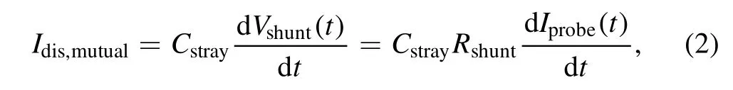
whereIdis,mutualis the mutual capacitance current.The key issue of this effect is that it acts on the voltage across the shunt resistor,i.e.the signal of theI-Vtrace itself,instead of theVbias.This makes mutual capacitance difficult to eliminate without knowing theI-Vtrace in advance.In addition,Idis,mutualis directly proportional toRshunt,facilitating the need to minimizeRshuntto reduce this effect,but a minimizedRshuntalso reduces signal strength and the signal-to-noise ratio of the probe current,making DAQ more difficult.On the other hand,mutual capacitance effect is by nature a second order effect resultant from the circuit reaction to the probe current,and depends onVshuntwhich indeed can be reduced by reducingRshunt.Thus unlessRshuntis considerably large,mutual capacitance effect is expected to be very small.This will be experimentally demonstrated in this work.Note that there is an additional limit to the shunt resistance:Rshuntmust be much smaller than the estimated characteristic sheath resistanceRsheath~eIesat/kTewhereIesatis the electron saturation current andkTeis the electron temperature in eV.IfRshuntis not much lower than the characteristicRsheath,the slope of theI-Vtrace dIprobe/dVbiasbecomes limited by theRshuntinstead ofRsheath,which results in unreliable data.
Finally,the sheath capacitance current is given by the following equation:
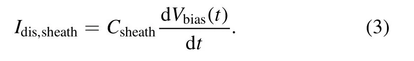
At first sight,sheath capacitance behaves very similarly to circuit capacitance,particularly considering the reaction current toVbias(t).Indeed sheath capacitance is often neglected as they are very small compared to the circuit parasitic capacitance[7].However,an important deviation betweenCstrayandCsheathis thatCsheathin fact varies withVbiasdue to the changes in sheath thicknesses.Chen[20,21]gaveCsheathas the following equation:

whereAprobeis the surface area of the Langmuir probe,ε0is the permittivity of free space and η is thekTenormalized sheath voltage drop.One can see that α is essentially a sheath-thickness parameter that changes withVbias.Equation(3)estimates the sheath capacitance of an ion sheath and a similar approximation can be given for the thickness of an electron sheath with a ~0.4 ratio smaller than that of an ion sheath[22].Using these approximations,we can estimate the evolution of the ion sheath associated parameter αi,the electron sheath associated αeand the associatedI-Vtrace distortion by only the ion sheath associated displacement currentIdis,s,iand both ion and electron sheath associated displacement currentIdis,s,i+e,as shown in figure 1.Generally sheath capacitance is on the order of a few pF and is much smaller than the circuit capacitance[7],the distortions in figure 1 have been multiplied by a large factor for readers to better understand its complicated effects.
Note that the first order displacement current from the sheath capacitance remains acting on the rate of change of the probe bias dVbias(t)/dt,which is constant over a halfcycle for a triangularVbiaswaveform,as in this study.In addition,sheath models are known to have limited accuracy in experiments[7],and the zero capacitance point at the plasma potentialVpreflects a long-standing assumption that atVbias=Vp,the sheath near the probe disappears,an assumption which may not be true[15].Using this estimation nonetheless gives an idea of how the sheath capacitance,and thus its associated response current,evolves with probe bias.
4.Probe and circuitry design
Figure 2 shows the schematics of the probe construction as well as the two DAQ circuits employed in this study.The probe consists of a tantalum plate,with either 6 or 13 mm radius for different plasma densities,as the probe head,and is welded to a copper plated,0.8 mm diameter welding rod that runs along a double holed ceramic tube.The other hole of the tube holds another copper plated welding rod without the probe tip to serve as a null probe.The choice of two different probe sizes ensures sufficient signal strength for theI-Vtrace to be meaningfully analyzed considering the plasma density difference between the two discharge conditions.

Figure 1.(a)A rough illustration of the different stray capacitances in a typical Langmuir probe circuit,(b)estimation of α for ion and electron sheaths,and(c)distortion to the I-V trace sweeping up and(d)sweeping down by the estimated displacement currents resulted from both kinds of sheath capacitance.A baseline is subtracted from all I-V traces so that their minimum values are the same.
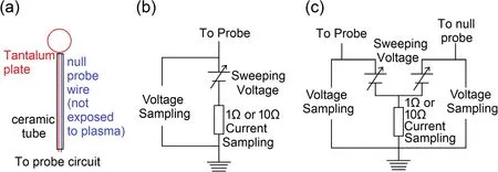
Figure 2.(a)A schematic diagram of the probe design,(b)the probe circuit of the Langmuir probe without the null probe,(c)the probe circuit of the Langmuir probe with the null probe.The null probe wire is not exposed to the plasma and only serves as a copy of the probe circuit to give the opposite displacement current from its stray capacitance.
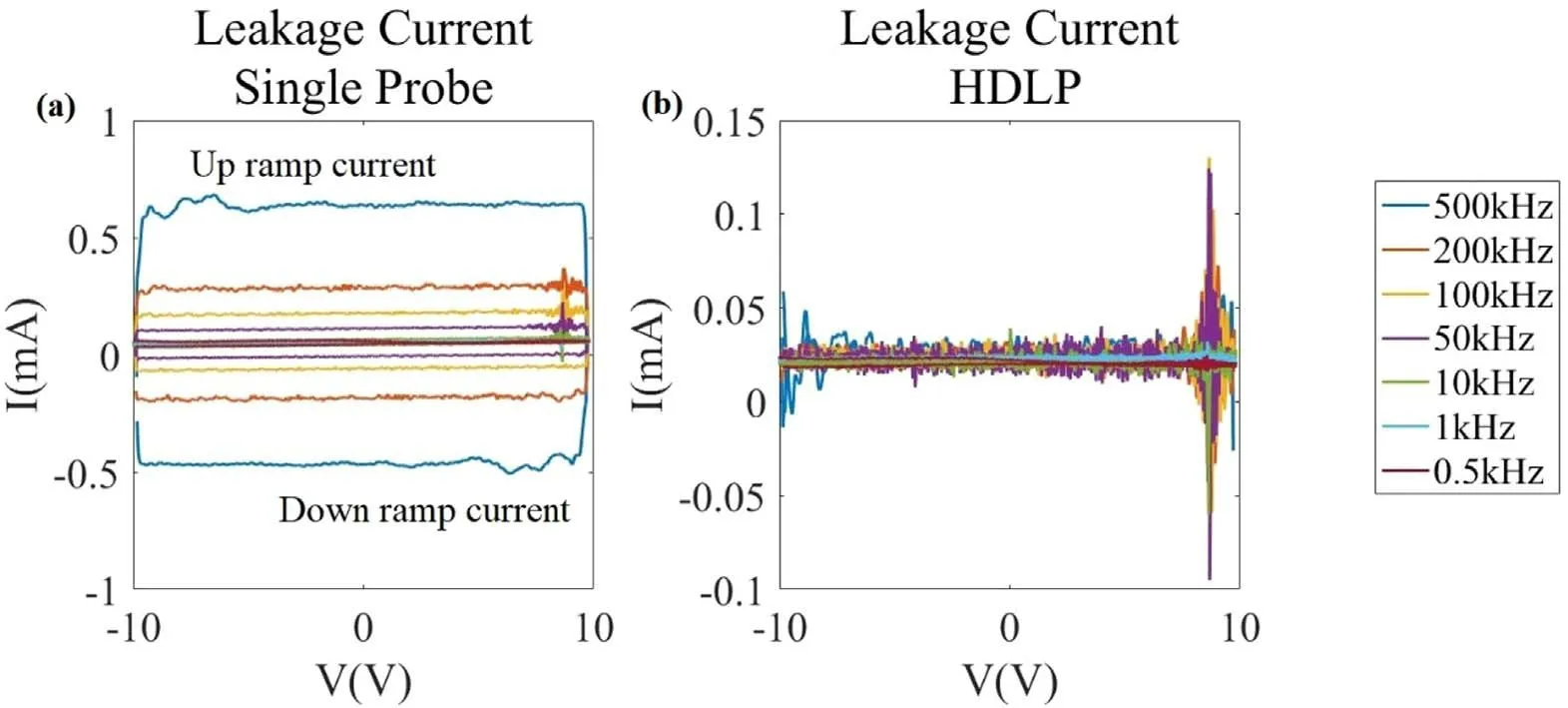
Figure 3.(a)Leakage current of the single probe,and(b)leakage current of HDLP setup.Note that some of the traces are being overlapped by the others.
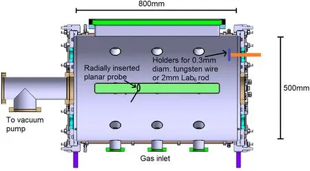
Figure 4.A schematic diagram of DTS-II.Note that the LaB6 rod cathode is inserted from one of the end walls and the Langmuir probe is inserted radially from a side window.
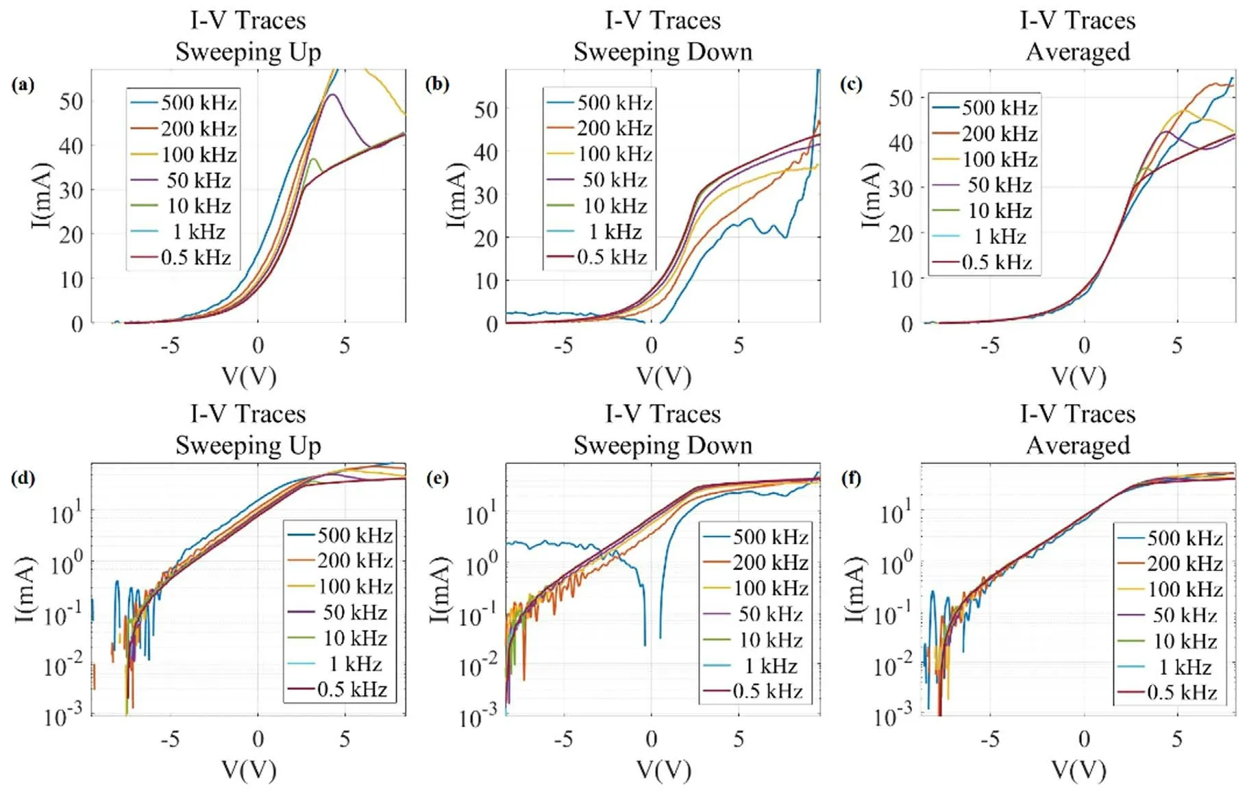
Figure 5.I-V traces at different frequencies of the single probe setup sweeping up(a),down(b)and both traces averaged(c)in linear scales in a Vprim=-100 V,IDis=1 A and PAr=0.034 Pa argon plasma with Rshunt=1 Ω.(d)-(f)Semi-logarithmic scales for figures(a)-(c)respectively.
Figure 6.I-V traces at different frequencies of the HDLP setup sweeping up(a),down(b)and both traces averaged(c)in linear scales in a Vprim=-100 V, IDis=1 A and PAr=0.034 Pa argon plasma with Rshunt=1 Ω.(d)-(f)Semi-logarithmic scales for figures(a)-(c)respectively.

Figure 7.Plasma densities,electron temperatures and bulk plasma potential calculated from the I-V traces of the single probe setup sweeping up(a),down(b),and both traces averaged(c),the I-V traces from which these parameters are calculated are shown in figure 5.
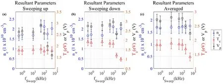
Figure 8.Plasma densities,electron temperatures and bulk plasma potential calculated from the I-V traces of the HDLP setup sweeping up(a),down(b),and both traces averaged(c),the I-V traces from which these parameters are calculated are shown in figure 6.
A triangular wave voltage sweep is performed by battery powered operational amplifiers capable of 28 V peak-to-peak bipolar output,with their input signals given by an isolated dual-channel function generator.The probe bias voltageVbias(t)is sampled by directly connecting a 70 MHz,2 GSa s-1oscilloscope between the positive sweeping voltage to the ground with no voltage dividing,and probe current is acquired by measuring the voltage of the shunt resistor.The oscilloscope has an input impedance of 1 MΩ and is expected to add a negligible parallel component to the circuit.The purpose of this study is to investigate systematic distortions to theI-Vtraces at high sweeping frequency.As such,random noises are purposefully discarded,so eachI-Vtrace is being averaged >10 000 times per the setting of the oscilloscope and data acquisition time is approximately 5-10 min,giving adequate time for the oscilloscope to average enough times.The choice of averaging a large amount ofI-Vtraces is made to eliminate random circuit noise limited by our electronics component and the laboratory electrical environment to obtain only the effect on theI-Vtrace consistent to the rapidly changing probe biasVbias(t),in particular,the associated sheath formation and any instabilities produced by the probe itself.While the choice of averaging a large amount of traces greatly reduces the temporal resolution of the diagnostics,the purpose of this study is to investigate the fundamental feasibility of a Langmuir probe withfsweep>fpi,and the practical implementation of such probes is out of the scope of this work.When we do not simultaneously acquire the reaction current,a typical probe circuit is employed as shown in figure 2(b).Simultaneously deduction of the reaction current is realized by setting a 180°phase difference between the optamp circuits connected to the real and null probe respectively,as shown in figure 2(c).The null probe and the real probe,now being swept at opposite polarity,are then connected to the same shunt resistor to realize native cancellation of the reaction current,similar to the setup in the[10].
The probe employed in this study is carefully designed to minimize parasitic capacitance:all conductive probe support has been removed or replaced with ceramics to remove coaxial capacitance,and the total wire length from the probe tip to the power supply is limited to within 100 cm,including the two ~20 cm wires(copper plated welding rods)that run through the ceramic tubes to the probe.All Bayonet Neill-Concelman(BNC)cables are replaced with parallel or single cables to avoid stray capacitance from the coaxial shielding.In addition,the shunt resistance for current sampling is selected to 1 Ω for high density case and 10 Ω for low density case to minimize mutual circuit response to the voltage across the shunt resistance.In addition,a high shunt resistance also tends to increase the charge/discharge time of the capacitances,i.e.serves as a damping element to the circuit.This introduces delay and therefore complication to the circuit response current,thus also facilitating the minimization of the shunt resistance.
Such circuit and probe design would severely limit the spatial accessibility of the probe in any practical devices,but this issue is beyond the scope of this work.
To investigate circuit capacitance effects for both the HDLP and the single probe setups,their leakage current was measured and were shown in figure 3.As shown in the figures,the capacitive response of the triangular waveformVbias(t)is a constant current over an up/down ramp half-cycle,and any resistive damping to the circuit can be characterized from the delay time with which this response current rises to its constant value at the edge of the triangular waveform.This translates into the voltage space with which the response current rises to a constant value on theI-Vtrace.As shown in figure 3(a),the resistive damping of the circuit in this work is found to be minimal.As shown in figure 3(b),the capacitive response has been well suppressed by the HDLP setup via the null and the real probes forming opposite displacement current through the shunt resistor.From the single probe leakage current,we can estimate the circuit capacitance from the response current equationIcap,stray=CstraydVbias(t)/dtto be ~25 pF.This is a very small parasitic capacitance compared to typical probe systems which haveCstrayon the order of >1 nF.Typical oscilloscopes have input capacitances on the order of 20 pF,which might be the dominant source of stray capacitance in this work.
The HDLP setup does not completely remove the circuit response,as shown in figure 3.It is important to note that the circuit response is not solely resistive and capacitive,particularly in the HDLP setup,as the‘residual’leakage current of the HDLP does not necessarily follow the first order derivative of the voltage waveform dVsweep/dt,which is constant over a half cycle of the triangular wave.These are expected to be either higher order capacitive response to the minute distortion of the voltage sweeping,the minute current noise of the operational amplifiers,or even the minute offset of the DAQ input.
5.Experimental setup
Experiments are performed in the Diagnostic Test Source-II(DTS-II)in the Institute of Plasma Physics,Chinese Academy of Sciences,the schematic of which is shown in figure 4.It is a 500 mm diameter,800 mm long multi-dipole confined hot cathode discharge device capable of direct current heated tungsten filament and LaB6rod cathode discharges.16 rows of permanent magnets are installed in the radial direction and each of the end walls of the chamber.A DC heated hot cathode discharge combined with multi-dipole confinement provides an unmagnetized and quiescent plasma free of source induced fluctuation.In this work,discharge is provided by a 15 cm long,2 mm diameter LaB6filament located on one end of the chamber,which is DC heated to emit energetic primary electron to produce the plasma.Our fastsweep Langmuir probe,inserted from a side window,is also shown in figure 4.
Experiments are performed with two sets of discharge parameters:one with a neutral pressurePAr=0.034±0.002 Pa,a cathode biasVprim=-100 V,and a discharge current of 1 A,this results in a plasma densityne=(1.6±0.2)×1010cm-3,an electron temperatureTe=1.8±0.3 eV,and a plasma ion frequencyfpi≈4.2 MHz.Another set of discharge parameters has a neutral pressure of 0.0019±0.0002 Pa and a discharge current of 0.012 A.The resultant plasma has an electron densityne=(2±0.5)×107cm-3,electron temperatureTe=1.7±0.3 eV,and plasma ion frequencyfpi≈150 kHz.The choice of the two sets of discharge parameters enables investigation of effects associated with fast probe bias sweeping whenfsweep≪fpiandfsweep>fpi,despite usable sweeping frequency is currently limited to 500 kHz.
6.Results and discussion
6.1.fpi≫fsweep,the ‘typical’ fast sweeping Langmuir probes
Typical fast sweeping Langmuir probes are employed in plasmas wherefpi≫fsweep,where distortions of theI-Vcharacteristics are known to be dominated by the circuit response.This is a common experimental scenario where a perturbation well below the ion plasma frequency,like a Hall thruster breathing mode[23]or a plasma turbulence[24],is investigated.
Figures 5 and 6 show a series ofI-Vtraces from a 6 mm diameter tantalum Langmuir probe using the single probe and HDLP setup sweeping up and down at variousfsweep,in a neutral pressurePAr=0.034 Pa argon plasma where the cathode biasVprimis-100 V and the discharge currentIDisis 1 A.Figures 7 and 8 show the resultant plasma parameters from theseI-Vtraces.The low frequency traces give the plasma densityne=(1.6±0.2)×1010cm-3,electron temperatureTe=1.8±0.3 eV,and plasma ion frequencyfpi≈4.2 MHz,much higher than the maximum sweeping frequency 500 kHz in this work.

Figure 9.I-V traces at different frequencies of the single probe setup sweeping up(a),down(b)and both traces averaged(c)in linear scales in a Vprim=-80 V, IDis=0.012 A and PAr=0.0019 Pa argon plasma with Rshunt=10 Ω.(d)-(f)Semi-logarithmic scales for figures(a)-(c).
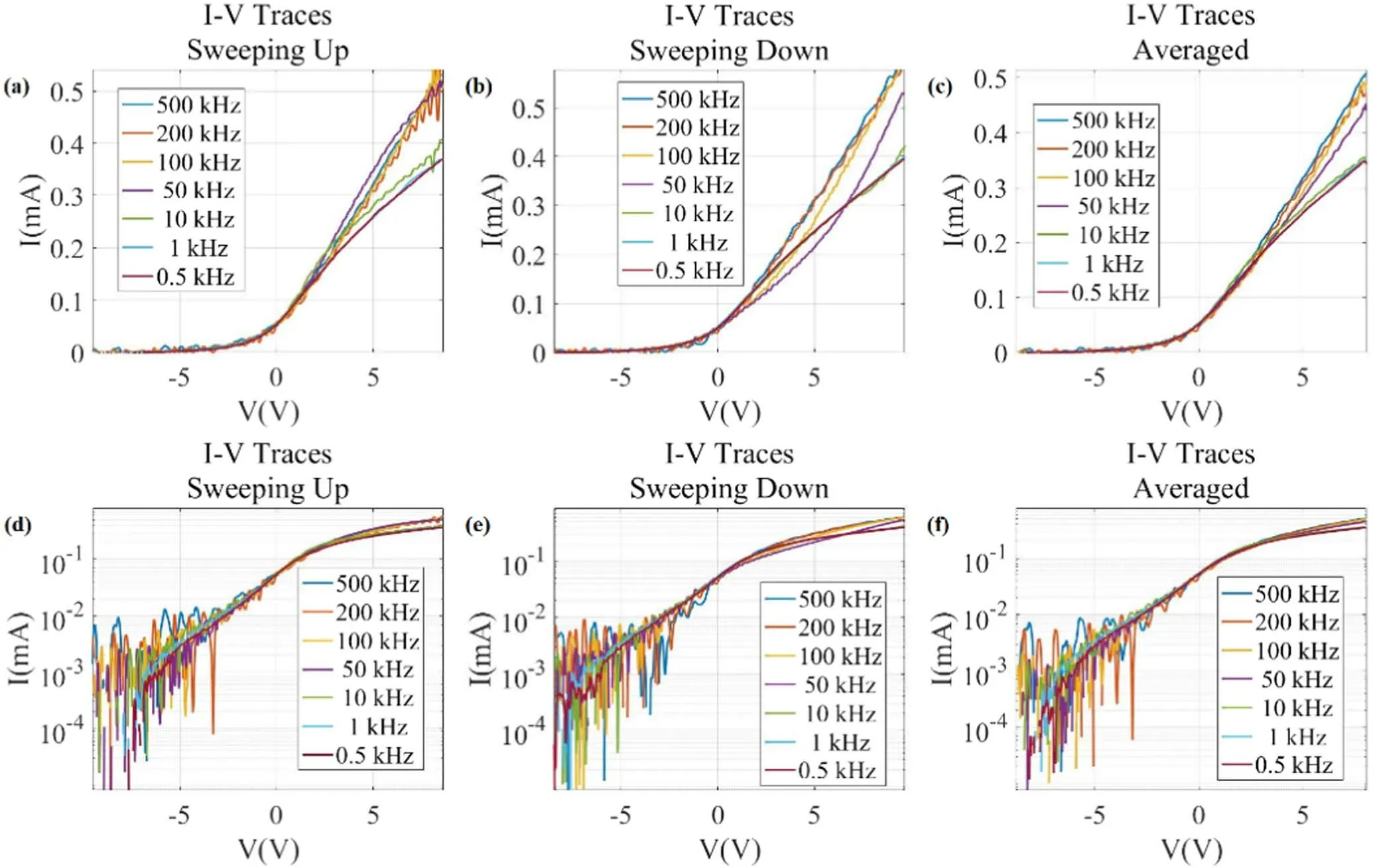
Figure 10.I-V traces at different frequencies of the HDLP setup sweeping up(a),down(b)and both traces averaged(c)in linear scales in a Vprim=-80 V, IDis=0.012 A and PAr=0.0019 Pa argon plasma with Rshunt=10 Ω.(d)-(f)Semi-logarithmic scales for figures(a)-(c).
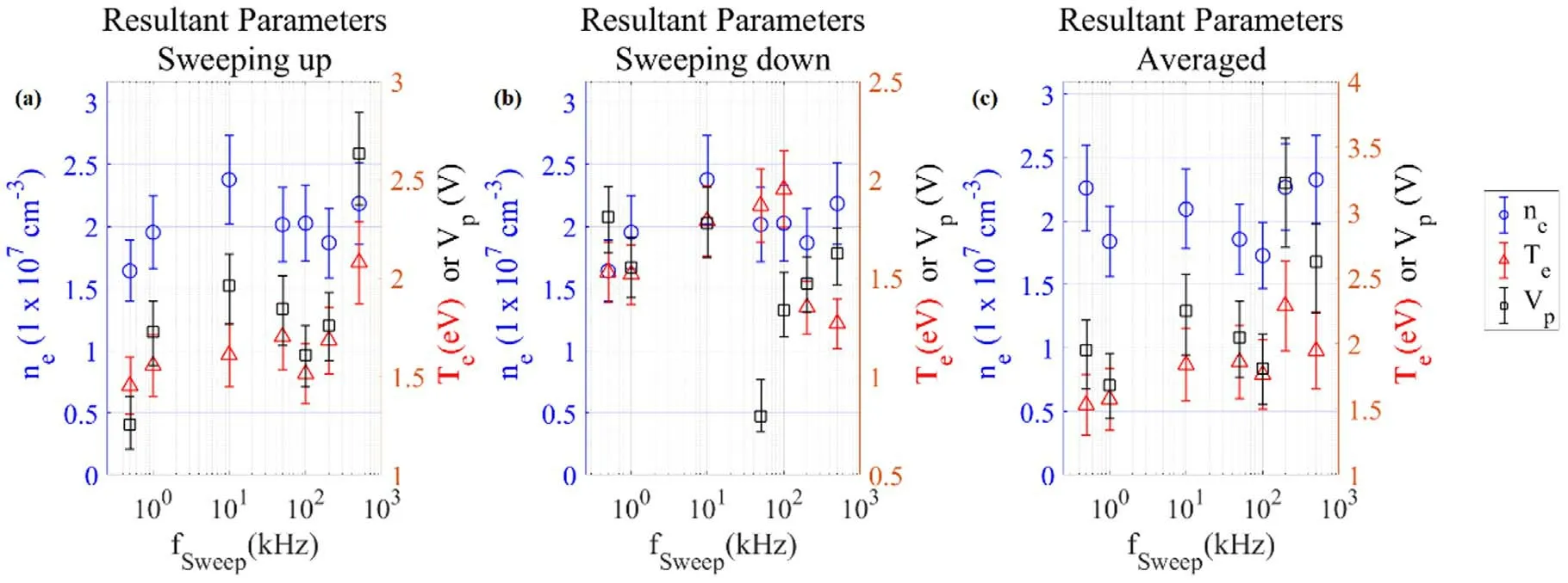
Figure 11.Plasma densities,electron temperatures and bulk plasma potential calculated from the I-V traces of the single probe setup sweeping up(a),down(b),and both traces averaged(c),the I-V traces from which these parameters are calculated are shown in figure 9.

Figure 12.Plasma densities,electron temperatures and bulk plasma potential calculated from the I-V traces of the HDLP setup sweeping up(a),down(b),and both traces averaged(c),the I-V traces from which these parameters are calculated are shown in figure 10.
Figure 13.I-V traces at different frequencies of the single probe setup sweeping up(a),down(b)and both traces averaged(c)in linear scales in a Vprim=-80 V, IDis=0.012 A and PAr=0.0019 Pa argon plasma with Rshunt=500 Ω.(d)-(f)Semi-logarithmic scales for figures(a)-(c).
With a voltage sweeping range limited to±10 V,the ion saturation current cannot be clearly obtained in a plasma as energetic electrons at >36 eV contributes to the electron current and can greatly reduce the floating potential.Therefore,rather than subtracting a linearly fitted ion saturation current,we simply add a baseline to theI-Vtraces post-DAQ to remove any negative current.This provides a qualitative comparison betweenI-Vtraces of differentfsweepas distortion of theI-Vtrace via capacitive response now becomes evident,although this eliminates all displacement current from the circuit response,as with ion saturation subtraction.
As shown in figures 5 and 6,at high plasma density and thereforefpi≫fsweep,both single probe and HDLP setups give almost identicalI-Vtraces,this implies that the displacement currents of circuit parasitic capacitance in response to dVbias(t)/dthave been effectively removed.However,we still observe a deformation of theI-Vtrace which is being increasingly severe as sweeping frequency increases,although saturation can still be observed when theI-Vtraces are semi-logarithmically graphed.Where previous studies claim these to be ion-motion related effects[14],we found distinctive features that suggest other possible mechanisms.
The young King went toward it and was about to take hold of it, but Trusty John, pushing him aside, seized it with his gloved hands, threw it hastily into the fire, and let it burn
First,the degree of this effect is much smaller than that observed in[14],particularly for the up sweeping half cycle,in fact,much of the ion-sheath portion of the distorted high frequencyI-Vtraces seem to exhibit a similar exponential slope as the undistorted,low frequencyI-Vtraces particularly in the semi-log graphs,resulting in very similarTemeasurements.In comparison,I-Vtraces in[14]were quite obviously distorted at significantly lower sweeping frequencies.
Second,we recovered the degree of distortion observed in[14]with a much higher shunt resistance,and the distortions would have distinctively different features than theI-Vtraces shown in figures 5 and 6,which will be discussed in the section below.
Finally,the distortions of the ion-sheath(Vbias<Vp)portion of theI-Vtraces are qualitatively agreed very well with the predicted distortions by sheath capacitance shown in figure 1 for both up and down sweeping traces.This suggests that these distortions are caused by the sheath capacitance which evolves asVbiaschanges.However,the sheath capacitance is typically expected to be a few pF or less[7],the planar probe used in this work is considerably bigger than typical HDLP setups where the probe tip is a small cylindrical probe tip.This much larger probe size might contribute to a vastly increased sheath capacitance,causing its associated distortions in figures 5 and 6 to be on par with the displacement current from the circuit capacitance shown in figure 3.This also suggests that the effects of sheath capacitance might have previously been underestimated.It should also be noted that the zero-capacitance point ‘predicted’ in figure 1 never appeared in figures 5 and 6,and the overshot of the electron saturation current is also quite different between figures 5 and 6 and the predictions shown in figure 1.This suggests that the transition from ion sheath to electron sheath and electron sheath formation has been more complicated than that predicted by conventional theories,as recent studies suggested[25,26].
It is also possible that the distortions of theI-Vtraces are caused by an ion-acoustic wave excited by the probe,which are expected to be natively in phase with the sweeping voltage.Again such effects require additional studies to verify the existence of such excited waves and possibly complex simulations to confirm its effect on theI-Vtraces,which are beyond the scope of this work.
Plasma parameters are extracted from theseI-Vtraces with the conventional method of fittingTeand the electron saturation current from theI-Vtrace in a semi-log graph.Interestingly,the resultant plasma parameters,particularly the electron temperature,given by these traces are not very different even with such distortion,and an agreement within typical Langmuir probe measurement error ofTeof approximately 20%,can be reached between differentfsweep,particularly with the up-sweeping traces and the up/down sweeping averaged.This is shown in figures 7 and 8.This suggests that the distortion current is somewhat anti-symmetric over an up/down sweeping cycle,which in turn is another evidence of sheath capacitance being the dominant effect behind theseI-Vtrace distortions,as the capacitive responseIdis,sheath=Csheath(dVbias/dt)flips sign over the up/down sweeping cycle and,in the absence of circuit inductance and resistance damping,is anti-symmetric over a sweeping cycle.The discrepancy between theI-Vtraces nearVpand in the electron saturation current portion might be due to some possible forms of hysteresis of sheath mode transition,leading to a different evolution ofCsheathat the electron branch.Note that hysteresis of sheath mode transition is a known issue in other sheath related studies[27,28].
6.2.fsweep>fpi cases
Withfsweepelectronically limited to a few hundred kHz,the plasma density is reduced to obtain experimental scenarios wherefsweep>fpi.This is done by limiting neutral pressure to 0.0019±0.0002 mPa and discharge current to 0.012 A.The resultant plasma has an electron densityne=(2±0.5)×107cm-3,electron temperatureTe=1.7±0.3 eV,and plasma ion frequencyfpi≈150 kHz,much lower than our maximum sweeping frequency of 500 kHz.Considering that the exponential transition region occupies less than 1/3 of theI-Vtraces,fsweep/fpiis approximately 10,and ions can thus be considered stationary while sheath structure near the probe is transiting between an ion sheath and an electron sheath.

Figure 14.I-V traces at different frequencies of the HDLP probe setup sweeping up(a),down(b)and both traces averaged(c)in linear scales in a Vprim=-80 V, IDis=0.012 A and PAr=0.0019 Pa argon plasma with Rshunt=510 Ω.(d)-(f)Semi-logarithmic scales for figures(a)-(c).
Figure 15.Plasma densities,electron temperatures and bulk plasma potential calculated from the I-V traces of the single probe setup sweeping up(a),down(b),and both traces averaged(c),the I-V traces from which these parameters are calculated are shown in figure 13.
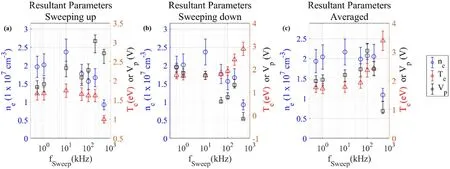
Figure 16.Plasma densities,electron temperatures and bulk plasma potential calculated from the I-V traces of the HDLP setup sweeping up(a),down(b),and both traces averaged(c),the I-V traces from which these parameters are calculated are shown in figure 14.
At much low plasma density andfsweep>fpi,distortions seem to appear at 50 kHz,a much lower frequency,and then slowly reduced asfsweepincreases.In light of sheath capacitive response being the dominant mechanism behind these distortions,it might not be surprising.Csheath,according to equation(3),is directly related to λDebyewhich is directly related to(ne)-1/2,while the saturation current,which determines the Langmuir probe’s signal strength,declines byne.Therefore,as density decreases the reduction of sheath capacitance via sheath expansion is outmatched by the reduction of the probe current,thus sheath capacitive effects become more apparent at a lower frequency.On the other hand,asfsweepapproaches and exceedsfpi,ions no longer participate in sheath formation as the ion transition time becomes shorter than the time scale in which sheath switches from an electron sheath to an ion sheath.This may result in an evolution of the sheath capacitance that is less fluctuating compared to that predicted in figure 1,therefore causing theI-Vtrace to be distorted more by a baseline from the constant dVbias/dtother than the wavy distortion current predicted in figure 1,the former of which is then eliminated in the process of subtracting the constant current baseline from theI-Vtraces.The exact sheath formation processes of the fast-sweeping probe and an accurate description of the evolution of the sheath capacitance,particularly with a rapidly changing sheath voltage drop,require experimental capabilities beyond what is currently available,and are out of scope of this study.It is also worth noting that the noise in theI-Vtrace increases with the sweeping frequency,as with the leakage current shown in figure 3.Since the leakage current is not associated with the plasma,it probably remained the dominant source of noise which is increasingly pronounced with an increasing temporal resolution setting of the oscilloscope asfsweepincreases.
To reproduce the observations by Trollet al[14],we have also attempted to obtainI-Vtraces in this low density,lowfpiplasma with a shunt resistance of 500 Ω for the single probe setup and 510 Ω for the HDLP setup with the 13 mm diameter probe.The choice of the low density case avoids the problem where the shunt resistance becomes higher than the sheath resistance and introduces additional distortions[29].For this plasma the sheath resistance is estimated to be 2 eV/
(e×0.2 mA)~10 kΩ,much higher than the 510 Ω shunt resistance.Sheath resistance effect is therefore isolated from this test.TheseI-Vtraces with high shunt resistances are shown in figures 13 and 14 and the resultant plasma parameters are shown in figures 15 and 16 for the single probe and HDLP setups respectively.Here we can see that the reappearance of the of theI-Vtraces at similar severity observed by Trollet al[14],which were unseen in the low shunt resistance setup as shown in the above sessions.In addition,the phase of the distortions is reversed:opposite to theI-Vtraces shown in figures 5,6,9 and 10,the distortions shown here in figures 13 and 14 reduces the current at the up sweeping cycle and increases the current at the down sweeping cycle.The sweeping voltage and the current are known to be in opposite directions in a Langmuir probe setup,thus a capacitive response that acts against the sweeping voltage will give a current at the same direction of the probe current,where a capacitive response that acts against the shunt voltage will suppress the shunt voltage.Therefore,it is expected that a possible mutual capacitance effect,which acts against the shunt voltage,will be at opposite direction to the sheath capacitance effect,which acts against dVbias/dt.This is in agreement with our experimental results.5 kΩ shunt resistance used by Trollet al[14],is much higher than even the ones employed in the high shunt resistance test in this work.It is highly likely that it is the sameI-Vtrace distortion being reproduced in this study,and the comparison ofI-Vtraces at different shunt resistances suggests that this effect is indeed mutual capacitance related.
7.Conclusion
In this study,we have revisited the known fast sweep Langmuir probe techniques and experimentally explored howI-Vtraces can be distorted whenfsweep>fpito answer a question:does limitation of ion motion prevent a Langmuir probe from being used at a sweeping frequency higher than the ion plasma frequency? Current results suggest that such usage of Langmuir probes is at least physically feasible,which reflects the fact that the Langmuir probe is,after all,an electron collecting probe and it is electron motion that dominates both the sheath formation near the probe and the resultant current that gives theI-Vtrace.
On the other hand,we found thatI-Vtraces can become distorted at sweeping frequency well belowfpipossibly due to the sheath capacitance which varies with the sheath thickness and thus create non-constant additional current to theI-Vtrace,despite the sweeping voltage is a triangular wave.This is not an ion-motion effect,but rather simply introduced by the sheath as a capacitive component separating the conducting probe and the conducting plasma,and its effects are expected to be electron flow dominated.Where other causes ofI-Vtrace distortions are not completely ruled out,the evidences presented in this study are,as known to the authors,the first possible evidences indicating the effects of the evolution of sheath capacitance with the sweeping voltage to theI-Vtrace in fast sweeping Langmuir probes.
The distortions of theI-Vtrace previously claimed to be ion-motion limitation effect[14]were only reproduced at higher shunt resistances,despite achieving a probe sweeping frequencyfsweep=500 kHz and a frequency ratiofsweep/fpi~3 and a transition time from the ion sheath mode to an electron sheath mode at approximately 1/10th of the ion transit time,showing that mutual capacitance effects are likely to be the cause of these previous observations.
In addition,with an experimental comparison,it is found that there are no physical differences between subtracting the capacitive response of the probe circuit for a single Langmuir probe setup and a HDLP setup.However,this statement comes in a condition that a triangularVbiaswaveform is used and a voltage divider is absent forVbiasacquisition.Otherwise,the complex displacement current and the non-zero leakage current can overwhelm the signal from the realI-Vtrace,complicating the corresponding DAQ system.
Acknowledgments
The authors would like to express their thankful acknowledgment in memory of the late Dr Noah Hershkowitz,Irving Langmuir Professor Emeritus of the University of Wisconsin-Madison,and a longtime collaborator of the authors who have given invaluable advice and discussions to our studies associated with sheath/presheath and diagnostics associated physics.The authors would also like to thank Dr Yevgeny Raitses of the Princeton Plasma Physics Laboratory(PPPL)and Dr Paul Dourbal at Members Exchange(MEMX)for their helpful discussions on high-speed circuitry.The authors would also like to give thanks to Prof Yongqing Wei of Hefei University of Technology for his insightful discussions on circuitry effects.This work is supported by National Natural Science Foundation of China(No.11875285),the CAS Key Research Program of Frontier Sciences(No.QYZDB-SSWSLH001),and the Chinese Academy of Science Hundred Youth Talent Program.
ORCID iDs
猜你喜欢
农业灾害研究(2022年1期)2022-05-07
科技研究·理论版(2021年20期)2021-04-20
当代工人(2019年23期)2019-12-30
广东教育·高中(2019年6期)2019-06-21
当代作家(2019年3期)2019-03-28
当代作家评论(2017年3期)2017-11-22
理科考试研究·高中(2017年7期)2017-11-04
福建文学(2017年3期)2017-03-11
红豆(2016年10期)2016-11-30
齐鲁周刊(2014年37期)2014-09-24
 Plasma Science and Technology2022年2期
- Plasma Science and Technology的其它文章
- Investigation of short-channel design on performance optimization effect of Hall thruster with large height-radius ratio
- Multi-layer structure formation of relativistic electron beams in plasmas
- Mode structure symmetry breaking of reversed shear Alfvén eigenmodes and its impact on the generation of parallel velocity asymmetries in energetic particle distribution
- Interaction between energetic-ions and internal kink modes in a weak shear tokamak plasma
- Investigation of the compact torus plasma motion in the KTX-CTI device based on circuit analyses
- Anomalous transport driven by ion temperature gradient instability in an anisotropic deuterium-tritium plasma