
Design and preliminary test of a 105/140 GHz dual-frequency MW-level gyrotron
2022-04-15 05:13LinlinHU胡林林DiminSUN孙迪敏QiliHUANG黄麒力TingtingZHUO卓婷婷GuowuMA马国武YiJIANG蒋艺ShenggangGONG龚胜刚ZaojinZENG曾造金ZixingGUO郭子星ChaohaiDU杜朝海FanhongLI李繁宏HongbinCHEN陈洪斌FanbaoMENG孟凡宝andHonggeMA马弘舸
Plasma Science and Technology 2022年3期
Linlin HU (胡林林) , Dimin SUN (孙迪敏), Qili HUANG (黄麒力),Tingting ZHUO (卓婷婷), Guowu MA (马国武), Yi JIANG (蒋艺),Shenggang GONG (龚胜刚), Zaojin ZENG (曾造金), Zixing GUO (郭子星),Chaohai DU (杜朝海), Fanhong LI (李繁宏), Hongbin CHEN (陈洪斌),Fanbao MENG (孟凡宝) and Hongge MA (马弘舸)
1 Institute of Applied Electronics,Academy of Engineering Physics,Mianyang 621900,People’s Republic of China
2 Peking University, Beijing 100871, People’s Republic of China
Abstract A dual-frequency(105/140 GHz)MW-level continuous-wave gyrotron was developed for fusion application at Institute of Applied Electronics,China Academy of Engineering Physics.This gyrotron employs a cylindrical cavity working in the TE18,7 mode at 105 GHz and the TE24,9 mode at 140 GHz.A triode magnetron injection gun and a built-in quasi-optical mode converter were designed to operate at these two frequencies.For the proof-test phase,the gyrotron was equipped with a single-disk boron nitride window to achieve radio frequency output with a power of~500 kW for a short-pulse duration.In the preliminary short-pulse proof-test in the first quarter of 2021,the dual-frequency gyrotron achieved output powers of 300 kW at 105 GHz and 540 kW at 140 GHz,respectively,under 5 Hz 1 ms continuous pulse-burst operations.Power upgrade and pulse-width extension were hampered by the limitation of the high-voltage power supply and output window.This gyrotron design was preliminarily validated.
Keywords: gyrotron, megawatt, plasma heating, fusion application, dual-frequency
1.Introduction
Gyrotrons with MW-level power are indispensable sources for electron cyclotron heating and current drive (ECH&CD) in fusion devices (e.g.ITER, EAST, JT-60SA, DIII-D, W7-X,LHD and ASDEX-U) [1–3].Dual/multi-frequency or stepwise-frequency MW gyrotrons can enhance flexibility and performance for ECH&CD systems by providing a larger accessible radial range, a possible replacement of steerable antennas, and higher CD efficiency for stabilization of neoclassical tearing modes [2,4].Several MW-level gyrotrons of this type have been applied in fusion devices for two decades[5–8], e.g.the 105/140 GHz dual-frequency gyrotron of GYCOM,the 104/137/170/203 GHz four-frequency gyrotron of QST, and the stepwise-frequency (111.6–165.7 GHz)gyrotron of KIT.Institute of Applied Electronics, China Academy of Engineering Physics (IAE, CAEP) has recently developed some gyrotrons for fusion devices including a 28 GHz/50 kW/30 s gyrotron and a 28 GHz/400 kW/5 s gyrotron [9, 10].A 105/140 GHz dual-frequency MW-level continuous-wave(CW)gyrotron is being developed to meet the demand for domestic fusion devices for 105 or 140 GHz gyrotrons.At the end of 2020, a prototype gyrotron was fabricated.In the first quarter of 2021,a preliminary proof-test was conducted under short-pulse conditions.Gaussian beams with powers of 300 kW at 105 GHz and 540 kW at 140 GHz were achieved.
In this paper, the design of the main components of the gyrotron is introduced in section 2.Test results are presented in section 3, and conclusions are provided in section 4.
2.Design of the 105/140 GHz gyrotron
The main design parameters of the 105/140 GHz MW gyrotron are listed in table 1 and its diagram is shown in figure 1.The design goal for the tube is to produce an output power of 1 MW CW at two frequencies of 105 and 140 GHz.Thus,the key elements, i.e.resonant cavity, magnetron injection gun(MIG), quasi-optical (QO) mode converter and output window, must be able to work at both frequency points.Their design details are described below.
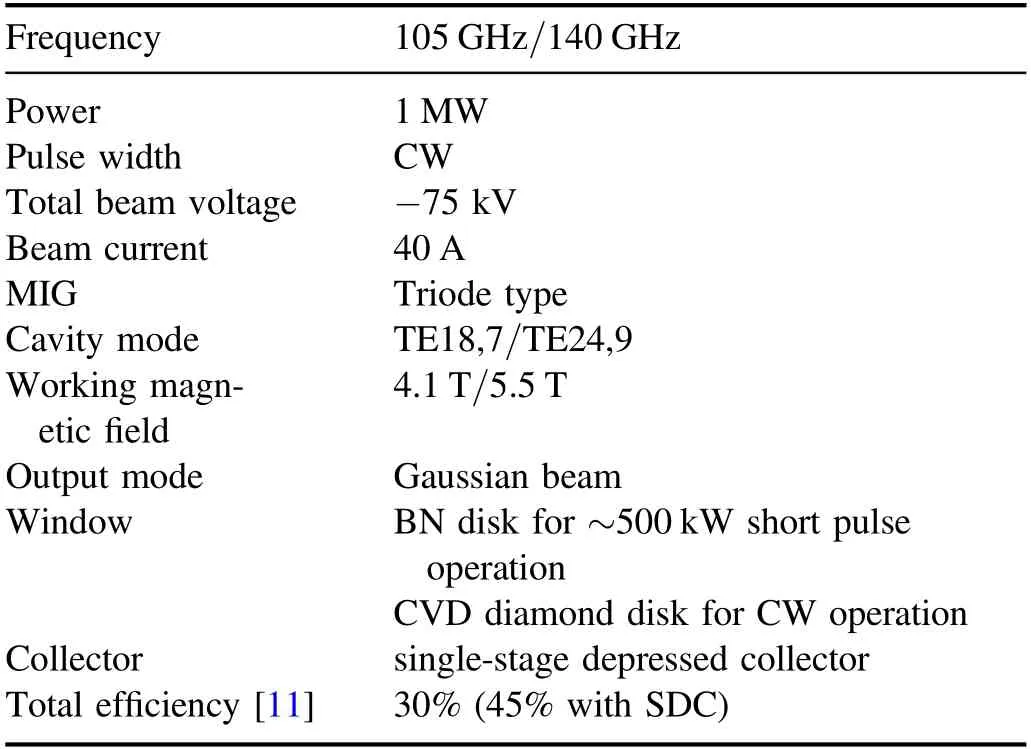
Table 1.Design parameters of the 105/140 GHz MW gyrotron.

Table 2.Design parameters of the cavity.
2.1.High-frequency resonant cavity
The following descriptions are major considerations for the candidate modes of MW-level gyrotrons [11]: (1) maximum wall loss power density below 2.0 kW cm-2;(2)quality factor Q of the cavity at ~1100;(3)for the dual-frequency gyrotron,the two working modes should have similarity in caustic radius and beam-wave coupling radius.
After comprehensive comparison,the matched mode pair TE18,7 and TE24,9 was selected to work at 105 and 140 GHz, respectively.The calculated parameters of the cavity are listed in table 2.The cavity consists of three classical sections, namely, a cut-off taper, a straight interaction midsection(interaction cavity),and an output taper.Structural optimization and beam-wave interaction analysis were iteratively performed using an in-house calculation code based on the nonlinear method[12].Figure 2 shows the dependences of the starting currents of the neighboring modes on the magnetic field for the two working modes under beam voltage,beam radius,and velocity ratio of-75 kV,8.678 mm and 1.2,respectively.Dense modes with similar starting current and magnetic field B were found near the working modes and classified as potential competition.

Figure 1.Design diagram of the gyrotron and superconducting magnet.
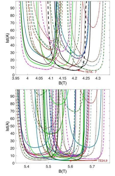
Figure 2.Calculated starting currents of TE18,7 mode TE24,9 and their neighboring modes.

Figure 3.Evolution of the produced power of the working mode and its competing modes calculated by the multi-mode time-domain method.
The most possible competitions for the working modes are those with similar eigenvalues and coupling factors.On the basis of starting current analysis, these modes were selected to evaluate their influence on the working mode by using multi-mode time-domain calculation [12].Figure 3 illustrates the simulated evolutions of radio frequency (RF)power and beam voltage over time under the magnetic field of B=4.14 T and B=5.46 T as follows.(1) At the initial rising of the beam voltage,several competing modes are excited,and the powers of these modes alternately fluctuate due to inherent mode competition.At this moment,the power of the working mode is growing slowly.(2)When the beam voltage continues to increase and reaches a stable condition(-75 kV), the power of the working mode increases rapidly,eventually becomes dominant, and reaches a steady output.The competing modes are suppressed, and their powers drop rapidly and eventually can be ignored.Hereto, the working mode wins the mode competition.
2.2.Magnetron injection gun
For successful application at the two frequencies, the MIG was designed to be a triode-type MIG consisting of a cathode,a modulation anode, and an anode.The modulation anode was employed to adjust a matched electrode voltages difference to keep the velocity ratio within 1.1–1.3 and velocity spread below 5%.Owing to the interaction cavity calculation,the design parameters of triode MIG were set as ~40 A emission current, ~-75 kV beam voltage, and 8.687 mm beam radius.The electrode structure, beam trajectory and magnetic field profile were iteratively optimized via PIC simulation code.Finally, the central radius and width of the emitter ring were set as 47.7 mm and 6 mm,respectively.The emission current was 42.4 A,which corresponded to a current density of 2.36 A cm-2.Owing to the voltage depression of 7.3 kV, the total beam voltage was -81 kV, and the kinetic energy of the beam at the cavity inlet was 73.7 keV.
Figure 4 shows the MIG structure and beam trajectories,and figure 5 displays the changes in the velocity ratio and axial velocity spread of the cyclotron beam as a function of the potential difference of the cathode and modulation anode(Vck).For the low working frequency of 105 GHz(B=4.1 T)or high working frequency of 140 GHz (B=5.5 T), an optimal range of Vckwas obtained to satisfy velocity ratio~1.2 and axial velocity spread ~3%.
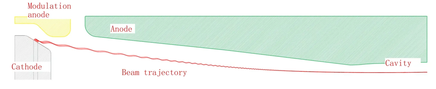
Figure 4.Triode MIG structure and beam trajectory.
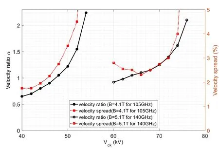
Figure 5.Calculated dependence of velocity ratio and axial velocity spread on the potential difference between the cathode and modulated anode.
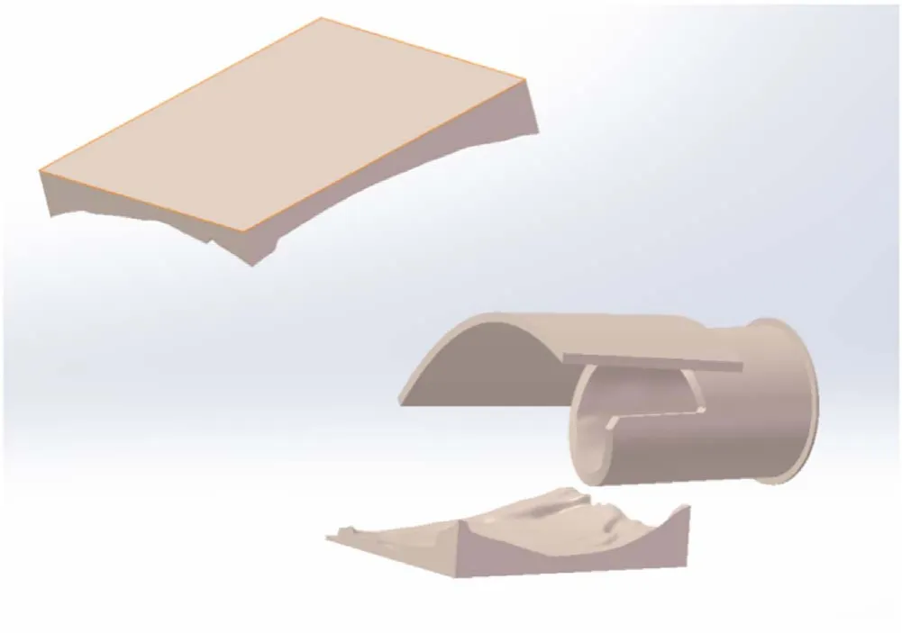
Figure 6.Structure of the quasi-optical converter.
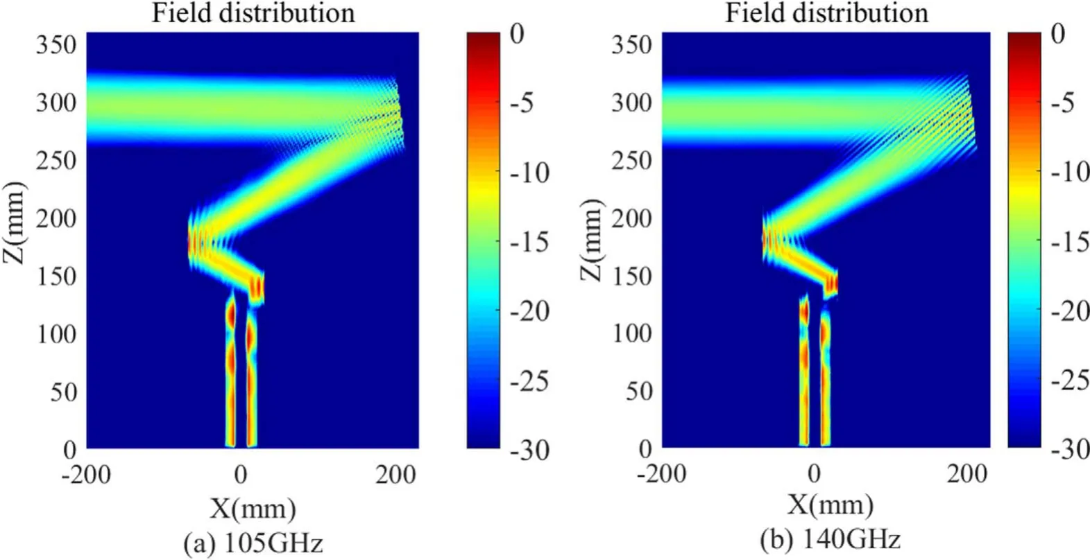
Figure 7.Calculated contour of the relative electric field (dB) at the cross-section of the quasi-optical converter.
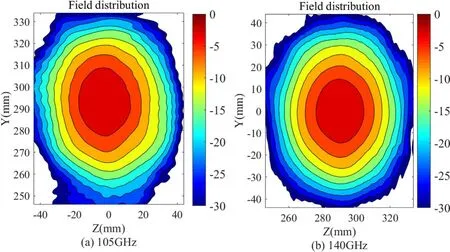
Figure 8.Calculated contour of the electric field distribution at the window surface.
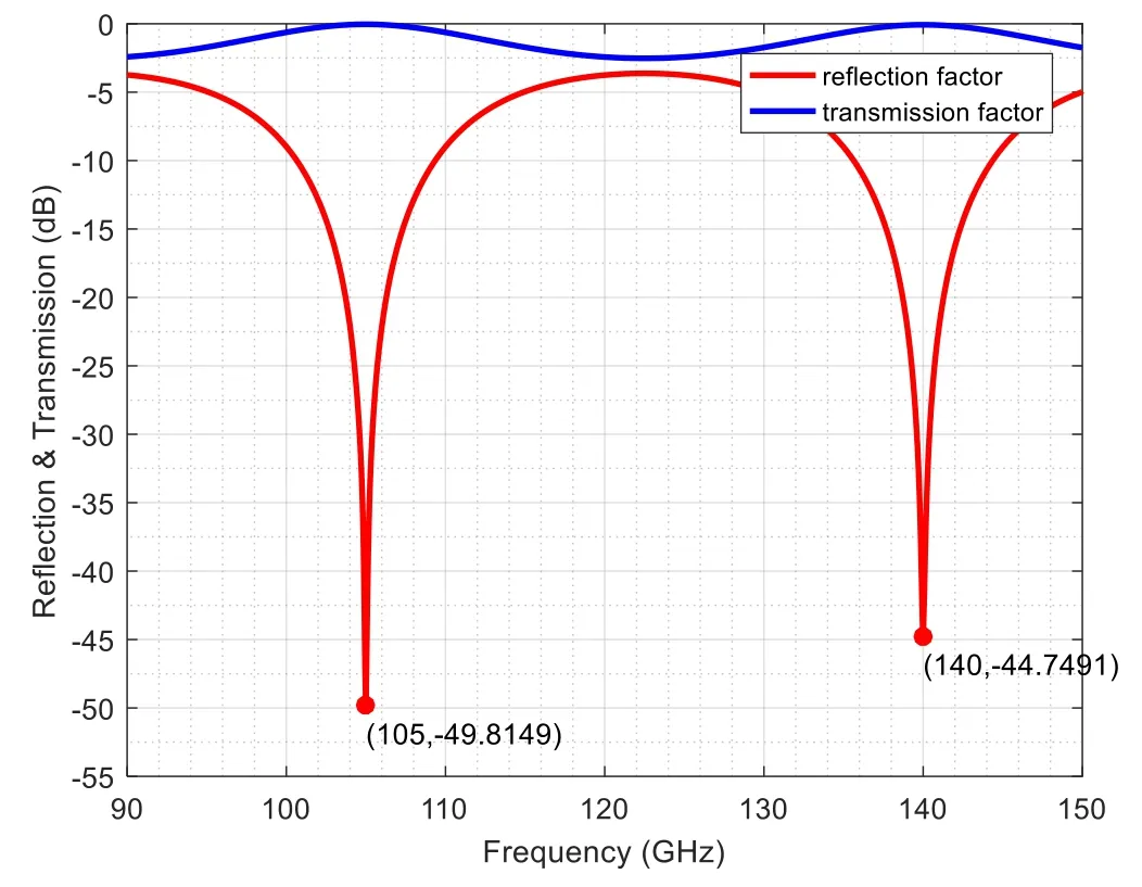
Figure 9.Calculated reflection and transmission factors of the window versus frequency.
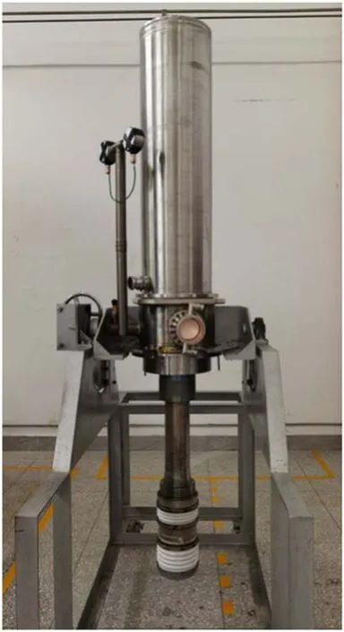
Figure 10.Photo of the 105/140 GHz MW prototype gyrotron.
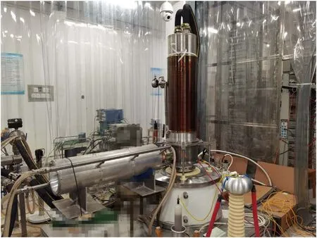
Figure 11.Test scene of the dual-frequency MW gyrotron.
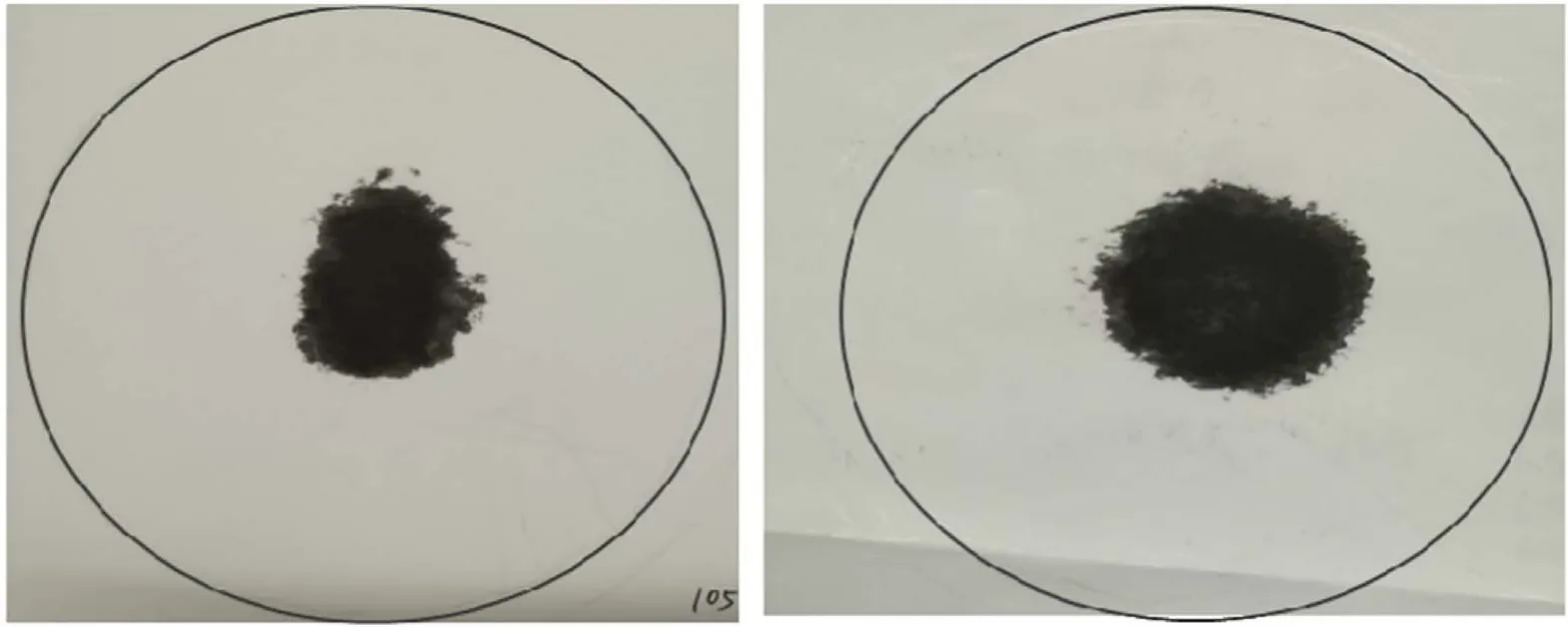
Figure 12.Thermal patterns of RF beams at the window aperture at 105 GHz (left) and at 140 GHz (right) obtained by 30 ms short pulses.
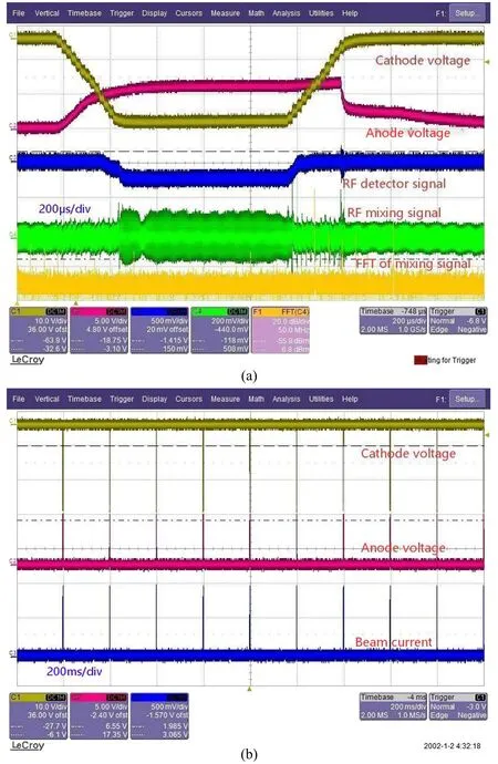
Figure 13.Oscillograph traces of the electrode voltages,microwave signals or beam current derived from(a)a single pulse operation and(b)a continuous 1 ms 5 Hz pulse burst operation.
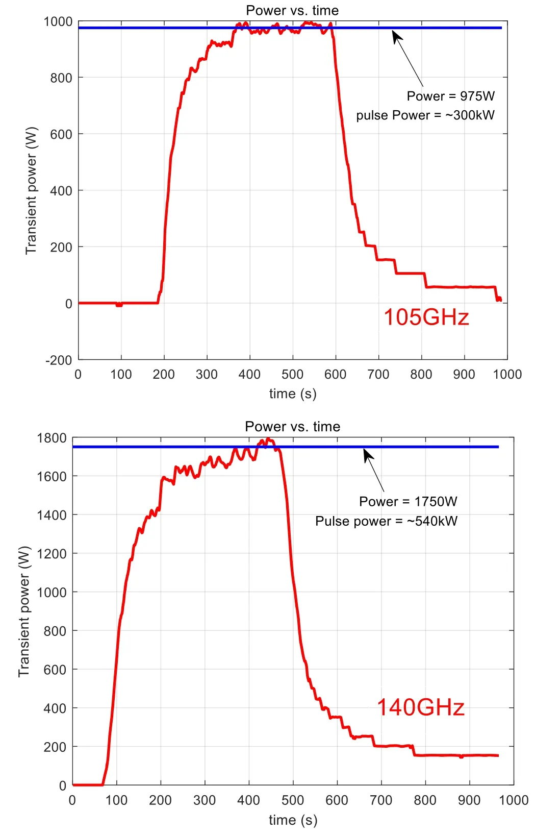
Figure 14.Transient power versus time obtained by the water load.
2.3.QO mode converter
A built-in QO mode converter was used to separate the spent electron beam from the RF beam and achieve the horizontal output of the latter.This mode converter was designed to operate at the two frequencies by ensuring similar parameters including helical cut length, Brillouin length, Brillouin width and Brillouin angle of the two modes (table 3).The waist radius of the Gaussian beam was 25 mm.
The QO mode converter consisted of a launcher and three reflection mirrors, as shown in figure 6.The launcher was connected to the end of the output taper of the cavity with an identical radius.The taper between cavity and launcher was a nonlinear taper.The first mirror was a quasi-parabolic reflector, and the second and third reflectors were used for phase correction.The launcher adopted the pre-bunching launcher scheme to improve the conversion efficiency of the RF beam[13].The surface irregular perturbation structure on the launcher wall was calculated and optimized by solving the scalar diffraction integral equation combined with the Katsenelenbaum–Semenov iterative optimization algorithm[14, 15].The complete mode converter was modeled and simulated by CST microwave studio.The electric field contours at the cross-section of the QO converter at 105/140 GHz are shown in figure 7.The calculated overall conversion efficiency and the scalar Gaussian mode content were 97.3% and 98% at 105 GHz, respectively, and 99.1% and 99.7% at 140 GHz, respectively.The distributions of the power density on the window surface are shown in figure 8.

Table 3.Transmission parameters of the QO converter transmission.
2.4.Window
For long-pulse/CW MW-level gyrotrons, the window must adopt CVD-diamond material[11,16].However,at the initial proof-test phase, a single-disk boron nitride (BN) window was planned and designed for 500 kW short-pulse operations.Compared with other materials except for CVD diamond,hexagonal pyrolytic BN material presents the advantages of higher thermal conductivity, lower thermal expansion coefficient, excellent high-temperature stability, good thermal shock resistance and good flexural strength [17].Tests of MW-level gyrotrons with BN windows revealed that singledisk BN windows can withstand a power capability of 930 kW for 2 s at 110 GHz and 960 kW for 1.2 s at 140 GHz under the quasi-uniform distribution of RF power [18].During the test of the 110 GHz BN-window gyrotron for DIII-D tokamak, the temperature increase of the BN disk was up to 930°C as observed by the infrared monitoring at the end of an 800 kW/2 s operation [19].
The parameters of the BN window were 90 mm diameter and 1.93 mm thickness.The thickness of the BN disk was just three half-wavelengths at 105 GHz and four half-wavelengths at 140 GHz to ensure that the window can work at the two frequencies.The calculated reflection coefficient and transmission coefficient as a function of frequency are shown in figure 9.The curves were derived using the dependence of loss tangent on frequency in[17],where tanδ=78×10-5at 105 GHz and tanδ=105×10-5at 140 GHz.For an output RF power of 500 kW, the predicted absorbed power of the window disk was 4.88 kW at 105 GHz and 8.7 kW at 140 GHz.The output RF beam was designed to be a fundamental Gaussian beam with a waist radius of 25 mm.Under the assumption that the thermal breakdown temperature of BN is 1000 °C from previous rest results [18], the thermomechanical analysis code Workbench predicted that the BNwindow gyrotron can operate for up to ~1.3 s at 105 GHz and~0.7 s at 140 GHz.
For the next phase,the BN window will be substituted by a CVD-diamond window for 1 MW, long-pulse or CW operation.
2.5.Other components
The beam tunnel of the gyrotron has an arbitrary non-axisymmetric conical metallic structure to suppress the parasitic oscillations[2].A single-stage depressed collector(SDC)was employed to improve the total efficiency.A longitudinal-field sweeping coil was installed outside of the collector jacket.A programmable current supply was planned to provide a periodic programmable current to the coil to ensure the timeaveraged heat dissipation from the spent electron beam at the collector below 0.5 kW cm-2[11].A cryogen-free superconducting magnet (SCM) with a 7.0 T magnetic field and a 220 mm diameter room temperature bore hole was accordingly developed The ceramic insulator was placed above the SCM.
3.Test results
The prototype gyrotron of the first version (figure 10) was fabricated at the end of 2020.The length and weight of the tube were 2.53 m and 300 kg, respectively.Proof-test was performed in the first quarter of 2021, and the test stand is shown in figure 11.The power supply system included a negative high voltage supply for the cathode, a positive supply for the anode and a filament supply.Owing to the lack of an extra source applied for the modulation anode, the modulation anode was grounded when conditioning at 105 GHz and was applied with voltage through a resistor divider connected with the anode supply when conditioning at 140 GHz.
Operating points at the two frequencies were first determined through single short-pulse conditioning.Images of the outgoing RF beam at the window aperture at 105 and 140 GHz were obtained on thermal paper during a 20 ms pulse-length operation.The thermal patterns in figure 12 qualitatively illustrate the Gaussian-like distribution, thus confirming the oscillations of the designed working mode at the two frequencies.The oscillation frequencies tested by the mixer method were 105.06 and 139.36 GHz.A typical oscilloscope trace of the electrode voltages and microwave signals of 1 ms single pulse operation is shown in figure 13(a).
With aging, the tube can steadily work at pulse-burst mode with a low duty cycle.The RF power of the gyrotron was measured by a dummy water-load under a continuous pulse burst operation mode.After the operation at 5 Hz repetitive rate, 1 ms pulse-width, and 2000 pulse number(i.e.duty cycle of 5%, 400 s), the power of the RF beam was 300 kW at 105 GHz and 540 kW at 140 GHz.The corresponding operation parameters are listed in table 4.The repetitive-rate traces of the electrode voltages and beam current are shown in figure 13(b).The transient power curves measured by the water load are displayed in figure 14.
Given the limitation of the cathode high-voltage power supply,the cathode voltage could not be increased further,the beam current could not be above 30 A, and pulse extension could cause instability.Thus, RF power upgrade and pulsewidth extension were hampered, and the preliminary prooftest of the gyrotron was ended.The instability was mainly manifested by the current surge at the modulation anode when the pulse width was extended.One probable cause is the plasma discharging due to the poor vacuum level at the MIG region.
Analysis of test results provides the following summary.(1) Owing to the limitation of high-voltage supply,the operating point was not optimized compared with the design parameters.Hence, the output RF power has not reached 1 MW full power.(2) The total efficiency was low, especially at 105 GHz because the status of the cyclotron beam was greatly affected due to the non-optimal operating point.(3) The design of the gyrotron was basically validated through check-calculation with the present test results.
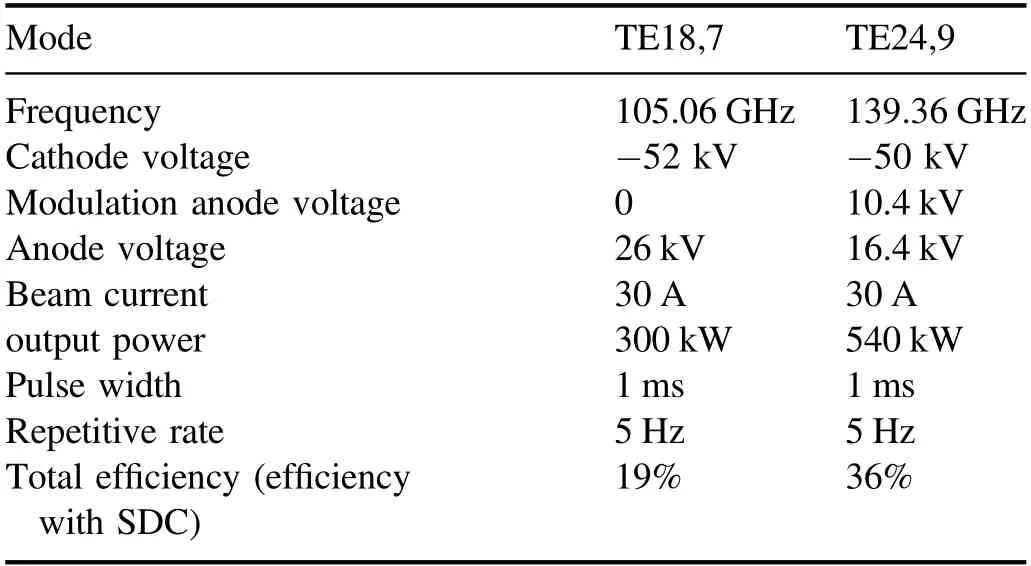
Table 4.Experimental result of the preliminary pulse test.
4.Conclusions
A 105/140 GHz MW-level gyrotron was designed,successfully fabricated and proof-tested in IAE, CAEP.At the preliminary pulse test,the gyrotron generated an output power of 300 kW at 105.06 GHz and 540 kW at 139.36 GHz during the 1 ms 5 Hz continuous pulse burst operation.Power upgrade and pulse length extension were hampered by the limitation of the high-voltage power supply and the output window.Given the non-optimal operating point, the current output power has not yet achieved 1 MW full power, and the efficiency is low.The proposed gyrotron design was basically validated.The work has laid a good foundation for power upgrade to MW-level and pulse-width extension to second-level at the next phase.
Acknowledgments
This work is supported in part by NSAF(No.U1830201),in part by the State Administration of Science,Technology and Industry for Nation Defense of China, Technology Foundation Project(No.JSJL2019212B006), in part by the Academy Innovation Funder(No.CX2020038),and in part by the National Defense Basic Scientific Research Program(No.2018212C015).
ORCID iDs
 Plasma Science and Technology2022年3期
- Plasma Science and Technology的其它文章
- A brief review: effects of resonant magnetic perturbation on classical and neoclassical tearing modes in tokamaks
- A classical relativistic hydrodynamical model for strong EM wave-spin plasma interaction
- Analysis of inverse synthetic aperture radar imaging in the presence of time-varying plasma sheath
- Analysis of the influence of sheath positions,flight parameters and incident wave parameters on the wave propagation in plasma sheath
- Transmission characteristics of terahertz Bessel vortex beams through a multi-layered anisotropic magnetized plasma slab
- Measurement and analysis of species distribution in laser-induced ablation plasma of an aluminum–magnesium alloy