
Experimental investigation on divertor tungsten sputtering with neon seeding in ELMy H-mode plasma in EAST tokamak
2022-06-29 08:55DaweiYe叶大为FangDing丁芳KedongLi李克栋ZhenhuaHu胡振华LingZhang张凌XiahuaChen陈夏华QingZhang张青PinganZhao赵平安TaoHe贺涛LingyiMeng孟令义KaixuanYe叶凯萱FubinZhong钟富彬YanminDuan段艳敏RuiDing丁锐LiangWang王亮GuoshengXu徐国盛GuangnanLuo罗广南andEAST
Chinese Physics B 2022年6期
Dawei Ye(叶大为) Fang Ding(丁芳) Kedong Li(李克栋) Zhenhua Hu(胡振华) Ling Zhang(张凌)Xiahua Chen(陈夏华) Qing Zhang(张青) Pingan Zhao(赵平安) Tao He(贺涛) Lingyi Meng(孟令义)Kaixuan Ye(叶凯萱) Fubin Zhong(钟富彬) Yanmin Duan(段艳敏) Rui Ding(丁锐)Liang Wang(王亮) Guosheng Xu(徐国盛) Guangnan Luo(罗广南) and EAST team
1Institute of Plasma Physics,HFIPS,Chinese Academy of Sciences(CAS),Hefei 230031,China
2University of Science and Technology of China,Hefei 230026,China
Keywords: neon seeding,tungsten sputtering,ELM suppression,EAST tokamak
1. Introduction
Tungsten(W)is foreseen as the most promising plasmafacing material (PFM) for the divertor in the ITER in terms of its high melting temperature,low sputtering yields and low deuterium retention rate.[1]With the increase of heating power in future fusion devices, extremely high power fluxes onto the divertor can cause significant erosion of the divertor material. Due to the absence of the intrinsic impurity radiation in full metal wall devices, extrinsic impurity seeding is considered as an indispensable way to reduce the energy deposited on the target. Simulations have shown that both neon (Ne)and nitrogen(N2)seeding can be used to dissipate significant amounts of power and to reduce the heat load on the divertor to an acceptable level(5 MW/m2–10 MW/m2)in ITER.[2]Although N2shows beneficial results in confinement enhancement and radiation increase in the edge plasma,the formation of partially tritiated ammonia affects the machine duty cycle in ITER deuterium–tritium plasma.[3]Therefore,Ne seems to be a better radiator in future fusion devices. However, as the W sputtering yield depends strongly on the incident particle species and their energies,Ne has a higher W sputtering yield than that of deuterium(D)or tritium(T)at the same incidence energy.[1]The existing simulation results reveal that the insufficient seeded Ne impurity could reduce the heat flux to the target, but the erosion of the W target can be obviously enhanced.[4]When the detached condition is achieved with sufficient Ne seeding, the W target erosion is obviously suppressed. In this work, the behaviors of W sputtering with Ne seeding in the divertor are experimentally observed and analyzed on EAST. The experiments reveal that the evolution of both the W sputtering rate and yield at the divertor target can be the competing results between two seeding effects,increasing divertor Ne impurity content and decreasing electron temperature,which is consistent with the simulation results.[4]In addition, ELM suppression has been observed in this Ne seeding experiment. Due to the W sputtering by seeded Ne impurities, both the W and Ne impurities in the core plasma significantly increase after Ne seeding in the upper divertor.The influence of Ne and W impurities on ELM behavior is discussed.
The rest of this paper is organized as follows: The experimental setup and method are introduced in Section 2. The effects of Ne seeding on divertor W sputtering are given in Section 3. The influence of impurity on the ELM is discussed in Section 4. Summary is presented in Section 5.
2. Experimental setup and method
EAST is an experimental superconducting tokamak device with a D-shaped poloidal cross-section and flexible divertor configurations, aiming at long-pulse high-performance H-mode operations.[5]The top W divertor with actively cooled ITER-like monoblock structure was installed in 2014[6]while the bottom W divertor was installed in 2021.[7]This work was carried out with the upper W divertor and lower previous graphite divertor as shown in Fig. 1(a). Meanwhile, the first wall in the main chamber is covered by molybdenum and graphite tiles.[7]EAST is equipped with a set of gas puff inlets distributed at the outer target, inner target, and dome of both top and bottom divertors. Only the inlet at the upper inner (UI) target was used for impurity seeding in this work as shown in Fig.1(b). The impurity seeding rate can be adjusted by changing the pulse voltage,duty,and frequency applied on the piezoelectric valve.
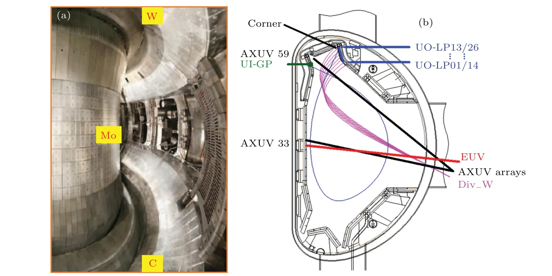
Fig. 1. (a) View into the EAST vacuum chamber and (b) geometry of viewing chords for the diagnostics used in this paper. Div-W (magenta):multichannel visible spectroscopy viewing the upper outer (UO) tungsten divertor; EUV (orange): extreme ultraviolet spectrometer; AXUV arrays(black): absolute extreme ultraviolet photodiode arrays with two bold lines indicating the 33th and 59th channels passing through the core and upper divertor region,respectively;UO-LP(blue): divertor Langmuir probes at the UO target,UO-LP01 to UO-LP13 at port D and UO-LP14 to UO-LP26 at port O;UI-GP(green): gas puff inlet at the upper inner(UI)target. A typical separatrix of main plasma is also shown with the blue line.
The multichannel visible spectroscopy system (Div-W)located in the equatorial port H[8]is used to monitor impurity line emissions especially the W I line at 400.88 nm in the upper divertor region. A schematic diagram of the lines of sight of the Div-W system is shown in Fig.1(b). The spatial resolution along the divertor targets is 13 mm and the temporal resolution is 5 ms in this work. Figure 2 shows a typical spectrum in the wavelength range of 396.2 nm to 427.nm with Ne seeding in the UI divertor. The line intensity of W I at 400.88 nm is used to quantify the W atom influxΓWby applying the inverse photon efficiency.[9]The W atom influx can be written as a function of the line intensity:[10]
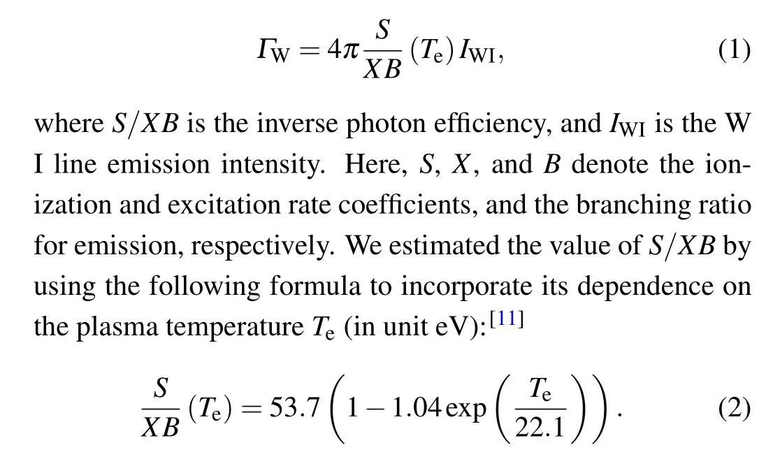
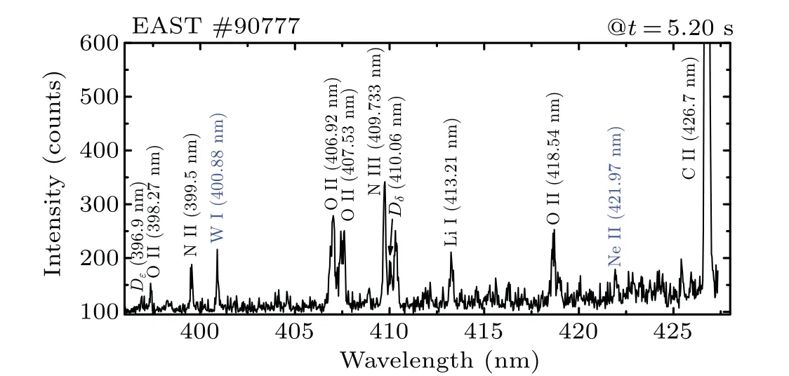
Fig. 2. A typical spectrum in wavelength ranges of 396.2 nm–427.6 nm obtained by the Div-W system in the USN H-mode plasma with Ne seeding.
In addition to the W I line at 400.88 nm,some lowZimpurity lines as well as neutral deuterium atom lines are also observed by the Div-W system as shown in Fig. 2, including O II (398.27 nm, 406.92 nm, 407.53 nm, 418.54 nm), N II (399.5 nm), N III (409.733 nm), Ne II (421.97 nm), Li I(413.21 nm),C II(426.7 nm),Dδ(410.06 nm),Dε(396.9 nm)etc.These emission lines are in good agreement with the NIST atomic spectra database. The high strength of the C II line in this spectral range can be attributed to the erosion of graphite plasma-facing components (PFCs) in the lower divertor and the guard limiter of antennae. Due to the lithium coating,the Li I line can be detected and used to evaluate wall coating conditions.[12]Line emissions from low-ionized oxygen and nitrogen ions may be due to the residual air absorbed in the PFCs and structural materials. The characteristic spectral line Ne II can be used as an indicator of Ne ion flux to the divertor target.[11]
Figure 1(b)illustrates the relevant diagnostics used in this work. In addition to the Div-W system, the absolute extreme ultraviolet(AXUV)photodiode arrays provide measurements of the radiated power in EAST plasma with fast temporal response (4 μs) and flat spectral sensitivity in the range from ultraviolet to x-ray.[13]Among 64 channels of the AXUV system,the 33th channel passes through the plasma core and the 59th channel views the upper divertor through the X-point region. The electron temperature(Tet)and ion saturation current(jsat) at the divertor target are measured by Langmuir probes embedded in the divertor target plate with a poloidal resolution of 12 mm–18 mm.[14]The line emissions of highly ionized impurities in the plasma core including W and Ne can be detected by the fast-time-response extreme ultraviolet (EUV)spectrometer in the wavelength range of 1 nm–50 nm.[15]An unresolved transition array (W-UTA) of tungsten ions in the core plasma,consisting of ionization stages in W27+–W45+,is clearly observed with strong intensity in the wavelength range of 4.5 nm–7.0 nm.[16]Thus the W-UTA signal provides an approximate estimation of the content of tungsten in the core plasma. The Ne X line intensity at 1.213 nm measured by the EUV system is used to monitor the Ne impurity content in the core plasma.
3. Effect of Ne seeding on divertor W sputtering
Ne impurity is normally seeded into the EAST W divertor to enhance the plasma radiation in order to achieve plasma detachment.[17]Figure 3 shows the time evolutions of the major plasma parameters in the USN H-mode discharge#90777 with Ne mixed gas seeding(volume ratio,Ne:D2=1:1).This discharge was operated in the favorable toroidal magnetic field direction withBt=2.5 T,plasma currentIp=400 kA,power injection of lower hybrid wavePLHW=2.5 MW (Fig. 3(a)),power injection of neutral beam injectionPNBI= 3.0 MW(Fig. 3(a)) and plasma stored energyWMHD= 150 kJ. Figure 3(a)shows that the voltage pulse of Ne seeding in the upper divertor starts at 4 s and lasts for about 500 ms. Most of the plasma parameters start to respond after a delay of about 400 ms. The time delay should be due to gas flowing in the pipe between the gas valve outside the machine and the gas inlet in the divertor. Afterwards the central lineaveraged electron densitynelincreases from 3.0×10¹⁹m-3to 3.5×10¹⁹m-3(Fig.3(b))and the peak ion saturation current density (jsat) at the upper outer divertor target increases slightly from 1.5 A/cm2to 2 A/cm2(Fig. 3(e)). The Ne II line emission in the divertor gradually increases until twice the value before seeding(Fig.3(c)).
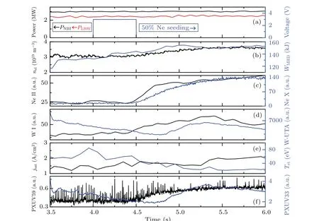
Fig.3. Time evolutions of the experimental parameters in discharge#90777 with Ne seeding. (a)Power source of NBI(black)and LHW(red)heating,and the voltage signal of the piezo valve for Ne seeding (blue); (b) the line-averaged electron density at the mid-plane nel (black) and plasma stored energy WMHD (blue); (c) Ne II line (black) emission measured by Div-W and Ne X line (blue) emission measured by EUV; (d) W I line emission measured by Div-W (black) and W-UTA measured by EUV (blue); (e) ion saturation current jsat (black) and peak electron temperature Tet (blue) at the UO target measured by divertor Langmuir probes; (f)AXUV 59th channel(black)measuring radiation across the upper divertor and AXUV 33th channel(blue)measuring radiation across the plasma core. The unit a.u. is short for arb. units.
Figure 3(f) shows the upper divertor radiation measured by the 59th channel of AXUV across the upper divertor has a similar trend as the Ne II line emission, indicating that Ne seeding could enhance the plasma radiation in the divertor.This could explain the decrease ofTetat the UO target from~50 eV to 20 eV due to the radiation cooling effect as shown in Fig.3(e). Despite the reduction of incident ion energy(proportional toTet),the W I line emission presents a rising trend until 5.3 s and then starts to drop(Fig.3(d)).
Figure 4 shows the distributions of W I line emission andTetalong the upper outer(UO)target.Thexaxis represents the distance along the UO target to the corner between the outer target and the dome as indicated in Fig. 1(b). The profile of W I line emission along the target is similar to that ofTet,indicating the strong dependence of the W sputtering rate on the incident ion energy in the spatial distribution. However, it is also seen that the W I line emissions around the peak keep increasing with time before reaching a maximum around 5.3 s,which is opposite to the temporal evolution of the correspondingTet.
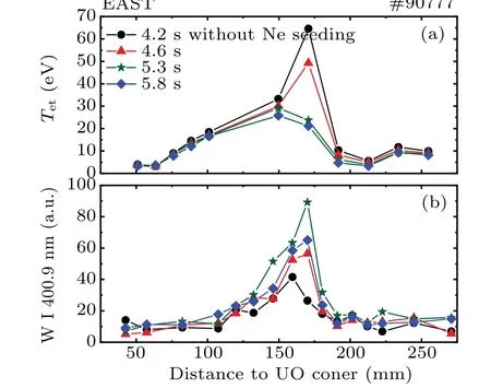
Fig. 4. Profiles at 4 different times of (a) W I line emission at 400.9 nm and (b) electron temperature Tet along the UO divertor target in discharge#90777 with Ne seeding.
To further understand the W sputtering behavior with Ne seeding,both the W atom flux(ΓW)and effective W sputtering yield (YW,phy=ΓW/jsat) are quantified based on the method as described in Section 2. Figures 5(b)and 5(c)plot the peakΓWandYW,phyagainst the peakTetand the Ne II line emission,respectively. Moreover,the dependences ofTetandjsaton the Ne II line emission are also illustrated in Fig. 5(a). It can be seen in Fig.5(a)that theTetdrops from 50 eV to 18 eV and thejsatrises slightly from 1.5 A/cm2to 2 A/cm2with the increase of the Ne II line emission. Especially when the relative Ne II line intensity exceeds 45,a rapid rise appears forjsatand thenTetdecreases to below 20 eV,which may indicate that the divertor plasma goes into a high recycling regime. These reveal that Ne seeding could change divertor plasma status and effectively reduceTetat the divertor target,thus causing a decrease of ion impact energy on W surface. However, the sputtered W atom flux does not present an immediate drop with the decrease ofTetas shown in Fig.5(b).
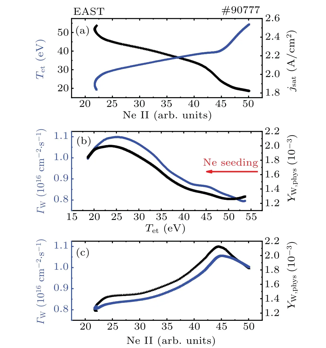
Fig.5. Effects of Ne seeding on the W sputtering at the UO divertor target.(a) Peak Tet and jsat at the UO target as a function of Ne II line emission intensity; (b) peak W atom flux ΓW and effective tungsten sputtering yield YW,phys(=ΓW/jsat)as a function of Tet;(c)peak ΓW and YW,phys as a function of Ne II line emission intensity.
On the contrary, the W atom fluxΓWinitially increases with the decrease ofTetuntil 25 eV. Then after a rollover,ΓWstarts to decrease withTet. The same trend is also observed for effective W sputtering yieldYW,phy, implying the dominant role ofYW,phyin the evolution ofΓW. Calculations by TRIM[18]in the binary-collision approximation predict that both the impact energy and the mass of incident particle have strong influences on the sputtering yield. The Monte Carlo simulation by Ouet al.also shows similar dependence of the W physical sputtering yield on the bombardment energy and different impurity ions.[19]Thus, it is considered that the Ne seeding decreases the divertor plasma temperature to reduce the impact energy of the incident particles on the one hand,but increases the Ne impurity concentration in the divertor plasma on the other hand. The dependence of W sputtering onTet,as shown in Fig.5(b), should result from the competition between the above two effects. The W sputtering increases gradually upon Ne seeding and theTetdecreases from 50 eV to 25 eV,where the Ne induced sputtering effect dominates. The W sputtering flux is observed to reach a maximum at 25 eV,nearly 50%increase relative to that before Ne seeding.The Ne seeding starts to have a net beneficial effect on the suppression of W sputtering whenTetdrops below 25 eV,where the cooling effect of Ne seeding dominates. A rollover for both sputtering atom flux(ΓW)and yield(YW,phy)similar to that in Fig.5(b)is also observed in Fig.5(c)when the relative Ne II line intensity exceeds 45 and the divertor plasma goes into a high recycling regime. These imply that the lower W sputtering rate due to the lowerTetin the high recycling regime could make compensation for the enhanced W sputtering by Ne impurity and the decreasing W redeposition rate,thus benefiting the control of core tungsten concentration as shown in Fig.3(d)that is to be discussed in the next section. This experimental observation is consistent with the simulation results in Refs.[20,21]. Due to the increase of particle flux onto the target with Ne seeding as shown in Fig. 5(a), the W sputtering rateΓWhas a faster rise before the rollover, but a slower drop after the rollover than the W sputtering yieldYW,phy. Therefore, small amount of Ne seeding enhances the W sputtering. Only when enough Ne particles are injected into the divertor plasma to reduce the plasma temperature sufficiently,can the W sputtering be effectively suppressed.
4. Influence of impurity on the ELM
Divertor impurities can partly transport into the core plasma due to the ion temperature gradient force,i.e.divertor impurity leakage.[22]It can be seen in Fig.3 that both the seeded Ne impurity and the sputtered W impurity in the UO divertor have strong influences on the main plasma. Figure 3(c)shows that the Ne X line emission at 1.213 nm starts to rise at 4.5 s after an~100 ms delay relative to the Ne II line emission in the divertor,indicating the penetration of Ne impurities seeded from the divertor into the core plasma.However,no obvious rise appears in the core XUV radiation signal(AXUV33 in Fig.3(f))at this time,although the divertor radiation channel AXUV59 presents a corresponding rise with the Ne II line emission. This indicates that the radiation contribution from Ne impurities in the core is moderate. Comparing the W-UTA spectral signal from the core W impurities and the AXUV33 signal as demonstrated in Figs.3(d)and 3(f),a good synchronization can be observed,indicating that the core plasma radiation is dominated by the W impurity. The rise of the W-UTA signal starting at 4.8 s should be related to inward transport of the W atoms sputtered in the divertor as discussed in Section 3. The W-UTA signal presents a good correlation with the W I signal in Fig. 3(d) since 4.8 s. The slow decrease of W-UTA intensity before 4.8 s is a recovery process after another W impurity event. In general,the plasma stored energy(WMHD)presents an opposite evolution with core tungsten radiation loss as shown in Fig.3. Moreover,the increasing density in the core should result from the injection of Ne mixture and partly contribute to the rise of plasma stored energy before 5 s,as shown in Fig.3(b). The subsequent decrease in plasma stored energy should be related to the increasing core W impurity radiation loss.It is also noticed that ELMs are evidently suppressed since 4.8 s,coincident with the rise of the W-UTA signal.
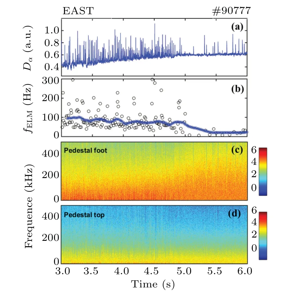
Fig. 6. Experimental results of ELM suppression during Ne seeding in#90777. (a) Dα signal in the upper divertor region; (b) ELM frequency;(c) and (d) the density fluctuation power spectra in the pedestal foot and pedestal top,respectively.

Fig. 7. (a) Density profiles reconstructed by the microwave reflectometry system at different times in the discharge #90777; (b) density gradient dne/dr corresponding to the curves in panel(a).
Figure 6 illustrates the temporal evolutions of the ELM frequency and the density fluctuation power spectra in the pedestal top and pedestal foot obtained by the microwave reflectometry.[23]The ELM frequency in Fig. 6(b) is calculated based on the divertorDαsignal in Fig. 6(a). The averaged ELM frequency (fELM) maintains at~100 Hz before 4.8 s. Most ELMs are suppressed since 4.8 s when the core W-UTA signal starts to rise.Simultaneously,figure 6(c)shows that the density fluctuation at the pedestal foot increases significantly with the rise of core plasma radiation,in which the fluctuations with higher frequency up to 400 kHz are excited after 4.8 s. This shows that the ELM suppression could be correlated to the enhanced transport induced by turbulence in the pedestal. The impurity transport across the pedestal may play an important role,which is similar to the observations in the HL-2A tokamak.[24]Figure 7 displays two density profiles measured by the microwave reflectometry before and during the ELM supersession.[25]The density gradient in the pedestal is softened during ELM suppression compared with that before,which could be attributed to the enhanced pedestal transport. These results indicate that ELMs can be suppressed due to the changed pedestal transport by impurities.
5. Summary
The influence of Ne seeding on the tungsten sputtering from the divertor target is investigated in the EAST experiment. The sputtered W atom influx at the divertor target has been quantified by using the spectroscopic observation on W I line emission at 400.88 nm. It is found that the W sputtering rate keeps an increasing trend with Ne seeding until the electron temperature at the target drops to below 25 eV where the W sputtering reaches the maximum.The competition between the drop of plasma temperature due to the radiation cooling effect of Ne impurities and the enhancement of W sputtering yield induced by the increased Ne impurity concentration in the divertor is the main reason. Enough plasma cooling is needed to obtain a beneficial W sputtering suppression for Ne impurity seeding.Moreover,the core plasma radiation is dominated by the W impurity content in the core and strongly correlated to the W source. The ELM suppression and enhanced turbulence transport in the pedestal are observed when the impurity radiation in main plasma exceeds a threshold, demonstrating the strong influences of divertor impurities on pedestal plasma behavior.
Acknowledgements
Project supported by the National Key Research and Development Program of China(Grant Nos.2017YFE0301300,2017YFA0402500,and 2018YFE0303103),the National Natural Science Foundation of China (Grant Nos. 12192283 and 12022511), the Users with Excellence Project of Hefei Science Center, CAS (Grant No. 2018HSC-UE008),the CASHIPS Director’s Fund (Grant No. BJPY2019B01),the JSPS-CAS Bilateral Joint Research Project (Grant No. GJHZ201984), and the Key Research Program of Frontier Sciences of CAS(Grant No.ZDBS-LY-SLH010).
- Chinese Physics B的其它文章
- Ergodic stationary distribution of a stochastic rumor propagation model with general incidence function
- Most probable transition paths in eutrophicated lake ecosystem under Gaussian white noise and periodic force
- Local sum uncertainty relations for angular momentum operators of bipartite permutation symmetric systems
- Quantum algorithm for neighborhood preserving embedding
- Vortex chains induced by anisotropic spin–orbit coupling and magnetic field in spin-2 Bose–Einstein condensates
- Short-wave infrared continuous-variable quantum key distribution over satellite-to-submarine channels