
Switchable and tunable triple-channel bandpass filter
2022-08-01 06:02MingEnTian田明恩ZhiHeLong龙之河LiJunFeng冯丽君LeiLeiHe贺磊磊andTianLiangZhang张天良
Chinese Physics B 2022年7期
Ming-En Tian(田明恩), Zhi-He Long(龙之河), Li-Jun Feng(冯丽君),Lei-Lei He(贺磊磊), and Tian-Liang Zhang(张天良),†
1School of Aeronautics and Astronautics,University of Electronic Science and Technology of China,Chengdu 611731,China
2Department of Mechanical Engineering,City University of Hong Kong,Kowloon,Hong Kong SAR,China
Keywords: independently adjustable,switchable,triple-channel
1. Introduction
Compared with the traditional fixed filter, a reconfigurable filter shows great advantages by supporting a variety of standards and operation modes in the system through its fast adjustment of center frequency and bandwidth. Besides,the reconfigurable filter can adapt to the high frequency band like the fixed filter.[1,2]Especially in recent years, with the development of wireless communication technology and remote sensing system, multiplexers and multichannel filters with reconfigurable performance have become a research hotspot. Taken into consideration in the multi-channel filter with fixed frequency is only the coupling between resonators and external feeding at several fixed frequency points,so it is easy to achieve.[3,4]For a dual-channel filter designed in Refs. [5,6], only the low-frequency channel has reconfigurable performance. Because the two modes constituting the high-frequency channel are not controlled by the varactor. In Ref. [7], a dual-channel filter is designed by using two pairs ofλ/4 uniform microstrip lines loaded with varactor diodes.The magnetic coupling is introduced by punching holes between the resonators, which not only saves the varactor used to control the interstage coupling but also forms a cascaded quadruplet model with the introduced cross electrical coupling to generate a pair of transmission zeros,thereby greatly improving the selectivity of the passband. In Ref.[8],a balanced feed is added into two tunable filters working at low frequency and high frequency respectively and thus obtaining a better inband reflection. In Ref.[9],the filter has the characteristics of dual-passband and dual-stopband by loading switching diodes on the main transmission line.
Although the filters in Refs. [7–9] have obvious advantages in passband selectivity, in-band reflection, and multifunction, they all use single-mode resonators to design two independent channels,which is not conducive to the miniaturization of devices. In Refs. [10–12], a compact dual-channel reconfigurable filter is designed by using a dual-mode resonator loaded with varactors. In Ref. [13], a dual-channel independently adjustable filter is designed using a ring multimode resonator,and a low-pass filter is cascaded to improve the high-end suppression. Although in Refs.[7–13]the dualchannel reconfigurable filters have been implemented,there is no channel selection function,and the two channels can work only at the same time. In Refs. [14,15], the extreme voltage is applied to the varactor to make a corresponding channel be in a serious impedance mismatch state, thereby realizing the channel selection function. In Refs.[16,17]the authors made the function of filter channel selection more stable and reliable by loading switching diodes.
In this paper, a switchable and tunable triple-channel bandpass filter is proposed. By loading switching diodes and varactor diodes on a cross resonator,the filter has four states:one single channel,two dual-channels,and one triple-channel,and each channel is reconfigurable in these four states.Finally,the varactor is also loaded at the external feed to make the external Q of the filter changeable and broaden the tunable range of the passband.
2. Design of reconfigurable filter
Figure 1(a) shows the layout of the switchable and tunable triple-channel bandpass filter presented in this paper. The core is a triple-mode cross resonator as shown in Fig. 1(b),which is the evolution of the cross resonator. Translating the lower branch to the leftd1enables channel 3 to obtain the appropriate coupling strength, which will be described in detail below.
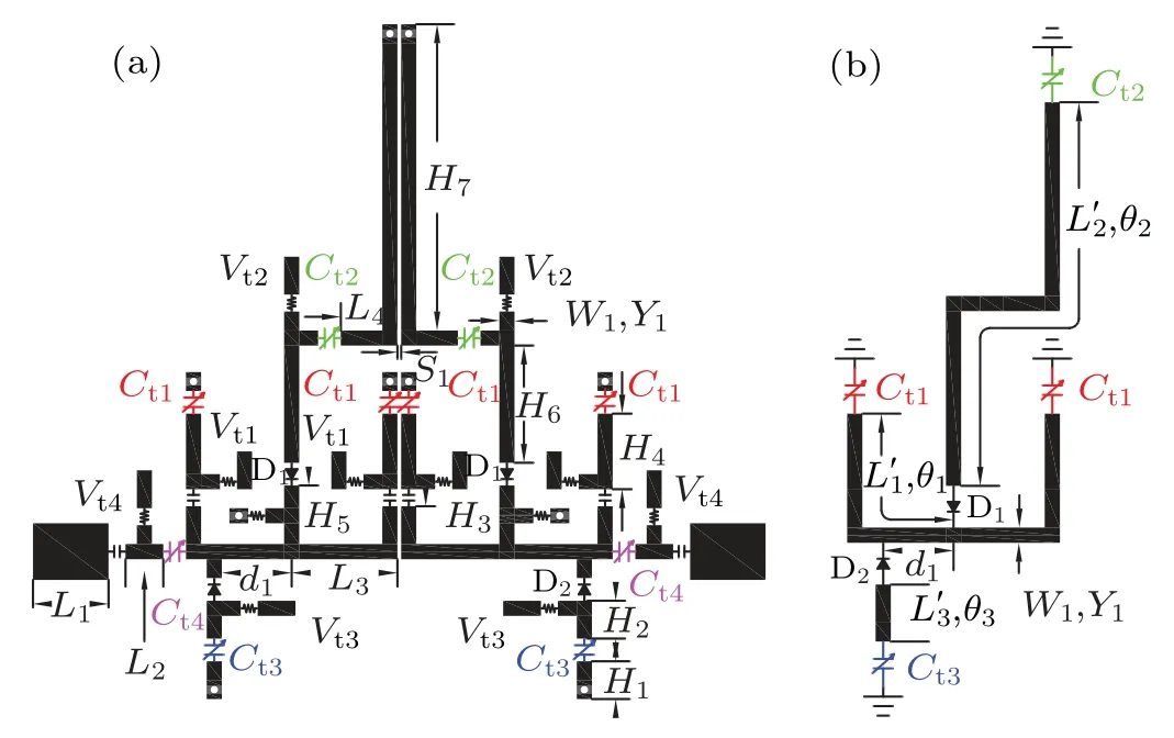
Fig.1. Layout of(a)filter and(b)resonator.
Because the offsetd1is small, the resonator can still be regarded as an approximately symmetrical structure, and the odd–even mode analysis method is still applicable to the resonator. The resonator is not only loaded with a varactor at the end of the microstrip line but also embedded with two switching diodes. When switching diodes D1and D2are off, the resonator is a single-modef1resonator,and the equivalent circuit is shown in Fig.2(a). When the switching diode D1is on and D2is off,the resonator is a T-shaped dual-mode resonator.According to the odd–even mode analysis method, the corresponding odd modefoequivalent circuit and even modefe1equivalent circuit can be obtained as shown in Figs. 2(b) and 2(c)respectively.When the switching diode D1is off and D2is on,the resonator is also a T-shaped dual-mode resonator. The corresponding odd modefoequivalent circuit and even modefe2equivalent circuit are shown in Figs.2(b)and 2(d)respectively. When the switch diode D1and D2are both on, the resonator is a triple-mode cross resonator,and the corresponding odd mode and even mode equivalent circuits are shown in Figs.2(b)–2(d).
Two resonators in Fig. 1(b) are arranged in parallel as shown in Fig.1(a),and the coupling between the same modes can form three channels. As the filter is schematically shown in Fig. 3, Channel 1 is formed at low frequencyfe1, channel 2 is generated at middle frequencyfoorf1, and channel 3 is created at high frequencyfe2. Therefore,when the switching diodes D1and D2are both off,only channel 2 works,which is a single channel state. When the switching diode D1is on and D2is off,both channel 1 and channel 2 work,which is in the dual-channel state.When the switching diode D1is off and D2is on,both channel 2 and channel 3 work,which is also a dualchannel state. When the switching diodes D1and D2are both on,channel 1,channel 2,and channel 3 work,which is in the triple-channel state. The corresponding relationship between switching mode and channel number is shown in Table 1.

Fig. 2. (a) Single mode f1 resonator, (b) odd mode fo resonator, (c) even mode fe1 resonator,and(d)even mode fe2 resonator.

Fig. 3. Schematic diagram of switchable and tunable triple-channel bandpass filter.
The center frequencies of the three channels of the filter designed in this paper are set to be 0.7 GHz, 1.5 GHz, and 2.5 GHz. The thickness of the substrate is 1 mm, the dielectric constant is 2.2,the microstrip linewidthW1is 0.8 mm and the admittanceY1is 0.01 S.According to the transmission line theory,the resonance conditions of the four equivalent circuits in Fig.2 can be obtained and expressed as Eqs.(1)–(4).
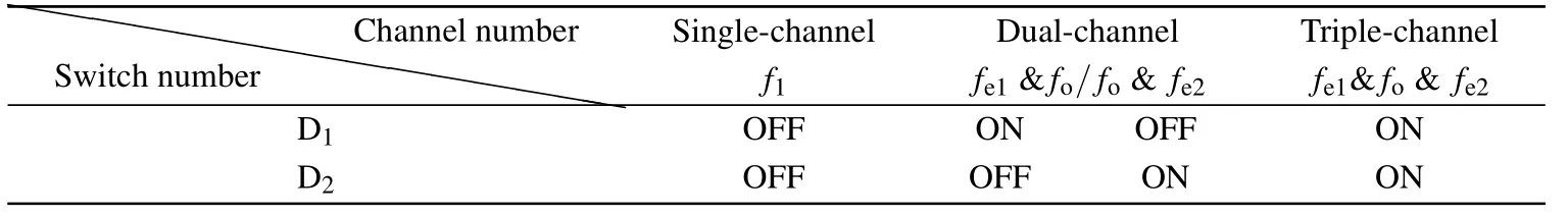
Table 1. Corresponding switch and channel number.
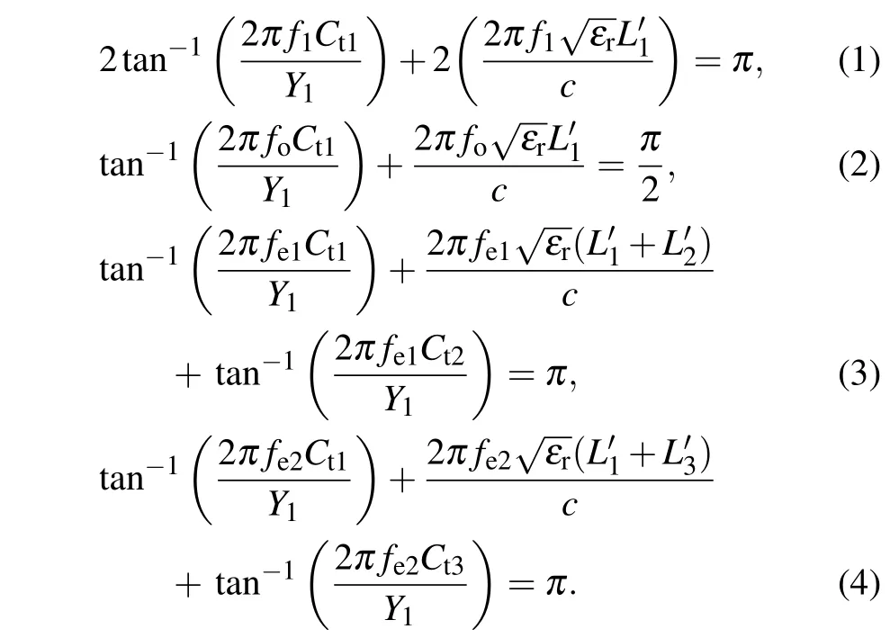
The transmission line theory used here involves mainly the resonance condition,input admittance and electrical length of the resonator. The electric length of the fundamental frequency of theλ/2 resonator and theλ/4 resonator areπandπ/2, respectively. Then, according to the forms of the four resonators in Figs. 2, figures 2(a), 2(c), and 2(d) can be classified asλ/2 resonator, figure 2(b) is classified asλ/4 resonator. Then, the capacitance is transformed into an equivalent microstrip line by means of the input admittance formula,so that the equivalent electrical length of the resonator can be acquired.
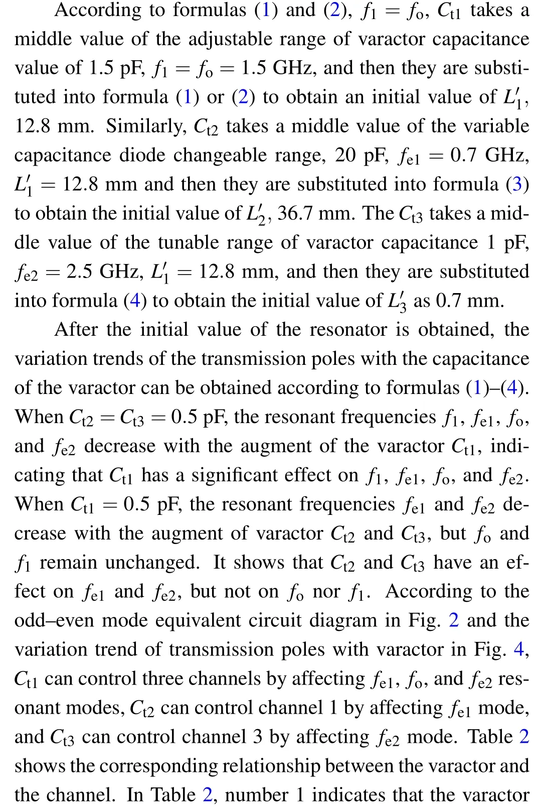
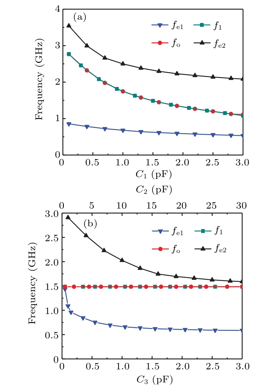
Fig. 4. Variation trend of transmission pole with capacitance of varactor,indicating (a) change trend of transmission pole with varactor Ct1 when Ct2 =Ct3 =0.5 pF,and(b)the change trend of transmission pole with varactor Ct2 and Ct3 when Ct1=0.5 pF.
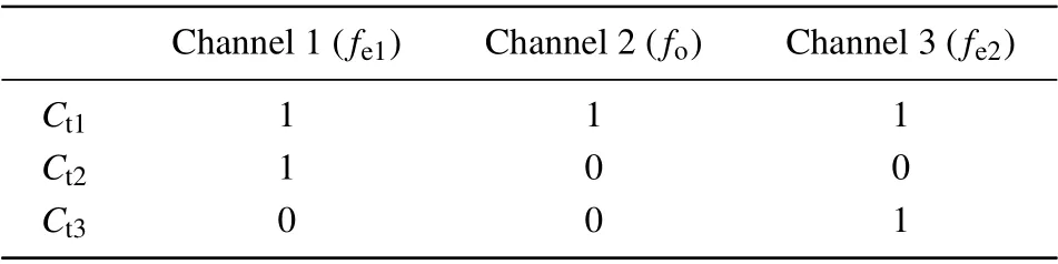
Table 2. Corresponding varactors and channels.

The channels of the single-channel filter,dual-channel filter,and triple-channel filter given in this paper each are independently adjustable,which are related to not only the number of varactor loaded but also the loading position. Usually, we first draw the odd-mode and even-mode equivalent circuit of the resonator, then observe the varactor controlling the mode constituting each channel,judge and infer whether each mode can be independently adjustable,and finally conclude whether each channel is independently tunable. However,the more the channels,the more complex the judgment is,here in this work a simple and rigorous judgment method named rank criterion is given.
Taking a triple-channel filter given in this paper for example, MatrixAcan be obtained from Table 2, and matrixBcan be obtained through row transformation. MatrixBis a third-order identity matrix with rank 3. Therefore, it can be concluded that if matrixAis a full rank matrix, each channel of the multichannel filter is independently adjustable. Thus,ifAis anm×nmatrix,wheremis the number of varactor diodes andnis the number of channels,the rank of matrixAisR(A).Ifm <norR(A)<n ≤m, the multichannel filter must not be independently adjustable for each channel,and the number of channels that can be independently adjustable isR(A). IfR(A)=n ≤m, the multichannel filter must be independently adjustable for each channel. Therefore,the necessary and sufficient condition for each channel of multichannel filter to be independently adjustable isR(A)=n ≤m.

Fig.5. Response curves according to EVCM.
Reference[15]gives a simple and effective method to design a reconfigurable bandpass filter. The response of the reconfigurable filter can be accurately characterized by the element variable coupling matrix. According to the presetting parameters of the filter(1.2 GHz–1.8 GHz,BW=150 MHz),the externalQvalue resonant frequency and coupling coefficient within the reconfigurable range can be obtained to accurately guide the design of the filter. The [MΔ]trepresents EVCM, the fixed component of matrix [MΔ]tis [MΔ],mkkis the self-coupling coefficient, [c]is the slope matrix,cQis the coefficient of external quality factorQe,fdis the calibration frequency,andftis the adjustable center frequency. Take the single channel in this paper for example, according to the element coupling matrix and the presetting tunable range, the frequency response curves can be obtained as shown in Fig.5.Now, the value ofmkkvaries in a range from-0.37 to 0.45,and the calibration frequencyfdis 1.5 GHz.

The lower branch of the resonator used in this work is shifted leftward byd1to regulate the coupling strength between thefe2of the two resonators. It is specified that the left offset of the branch from the midpoint is positive and the right offset is negative. As can be seen from Fig. 6, the coupling strengthkoffe2decreases with the increase of the offsetd1and the gapS1,indicating that after the gapS1is determined,the offsetd1can be adjusted to effectively control the coupling strengthk. After calculating the EVCM,kis obtained to be about 0.06,final gapS10.2 mm,and offsetd14 mm.

Fig.6. Variation trend of coupling strength k with offset d1 under different values of gap S1.

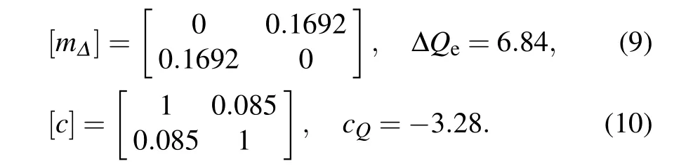
To meet the externalQvalue of the three channels, especially to broaden the reconfigurable ranges of the channels,the switchable and tunable triple-channel bandpass filter proposed in this paper adopts the varactorCt4feed at the port.Figure 7 shows the theoretical externalQvalues required in the tunable ranges of three channels and the actual externalQvalues extracted under differentCt4values from formula(11).WhenCt4becomes smaller or the frequency becomes larger,the externalQvalue of each channel becomes larger. Within the variation range ofCt4, the externalQvalues required by the three channels in their respective regulation range can be fully met. As shown in Fig.7,the line of theoretical externalQvalue required by each channel is sandwiched between the externalQvalue polyline whenCt4=2.5 pF and the externalQvalue polyline whenCt4=15 pF.The externalQvalue required by channel 2 within the adjustable range is analyzed by the EVCM method above. According to formulae (7)–(10),the externalQvalue is between 5.36 and 8.05. Considering the influence of in-band reflection, the calculation results are basically consistent with the scenarios in Fig.7(b),which also proves the reliability of the EVCM method.

Fig.7. External Q of(a)channel 1,(b)channel 2,and(c)channel 3.
3. Fabrication and measurements
Finally, the switchable and tunable triple-channel bandpass filter proposed in this paper is processed on the substrate with material F4BM-2, thickness of 1 mm and dielectric constant of 2.2. To prevent it from oxidizing, the circuit surface is plated with gold. The fabricated filter is shown in Fig. 8. According to the marks in Fig. 1(a), the specific dimensions are as follows:L1= 4 mm,L2= 2 mm,L3= 5.6 mm,L4= 4.4 mm,H1= 2 mm,H2= 2 mm,H3= 2 mm,H4= 3.2 mm,H5= 3.1 mm,H6= 6.2 mm,H7=16.2 mm,W1=0.8 mm,S1=0.2 mm,andd1=4.1 mm;the overall size of the circuit is 38.8 mm×35.7 mm (including DC bias circuit),i.e., 0.29λg×0.26λg. All varactor diodes are SMV1405-079LF(Cj=0.63 pF–2.67 pF)forCt1,SMV1273-079LF (Cj=2.15 pF–31.18 pF) forCt2andCt4,and SMV2020-079LF (Cj=0.35 pF–3.2 pF) forCt3. All resistors marked in the figure are 100 kΩ with package 0603,and the marked DC isolation capacitors are 39-pF Murata highQspecial capacitors with package 0603.

Fig.8. Fabricated switchable and tunable triple-channel bandpass filter.
Figure 9 displays the simulation and measurement results of the filter which shows that both switches D1and D2are both off. At this time,it is a single channel filter with a bandwidth of 150 MHz, an adjustment range from 1.27 GHz to 1.85 GHz, in-band reflection better than-15 dB, and there is a transmission zero point on the left and right side of the passband,which greatly improves the channel selectivity. Figure 9(b) shows that switches D1and D2are both on. At this time, it is a triple-channel filter. The low-frequency channel bandwidth is 200 MHz,the tunable range is between 0.46 GHz and 0.8 2GHz,the middle channel bandwidth is 200 MHz,the reconfigurable range is between 1.37 GHz and 1.71 GHz,the high-frequency channel bandwidth is 150 MHz, the changeable range is between 2.22 GHz and 2.70 GHz,and the reflection of the three channels is better than-13 dB.Figures 9(c)and 9(d)show the switch D1is on and D2is off. At this time,it is a dual-channel filter. When the high-frequency channel in Fig.9(c)is located at 1.62 GHz and the bandwidth is 150 MHz,the low-frequency channel bandwidth is 200 MHz,the tunable range is between 0.50 GHz and 0.86 GHz,and the in-band reflection of both channels is better than-13 dB.When the lowfrequency channel in Fig.9(d)is located at 0.65 GHz and the bandwidth is 200 MHz,the high-frequency channel bandwidth is 200 MHz, and the changeable range is between 1.41 GHz and 1.81 GHz. The in-band reflection of both channels is better than-13 dB.
Figures 9(e)and 9(f)show that switch D1is off and D2is on.At this time,it is also a dual-channel filter.When the highfrequency channel in Fig.9(e)is located at 2.37 GHz and the bandwidth is 150 MHz,the low-frequency channel bandwidth is 200 MHz and the adjustment range is between 1.32 GHz and 1.57 GHz. The in-band reflection of both channels is better than-18 dB,and the two transmission zeros greatly enhance the channel selectivity.The low-frequency channel in Fig.9(f)is located at 1.44 GHz, and the bandwidth is 150 MHz. The high-frequency channel bandwidth is 150 MHz, and the adjustment range is 2.21 GHz to 2.57 GHz. The in-band reflection of both channels is better than-16 dB, and the channel selectivity is improved obviously because of the two transmission zeros around the passband.
Table 3 shows the comparison in performance between the switchable and tunable triple-channel bandpass filter proposed in this paper and the multi-channel filters reported in the published literature. It can be seen from Table 3 that the filter proposed in this work is outstanding in terms of whether the channels are switchable and tunable, especially whether the three channels are independently adjustable.
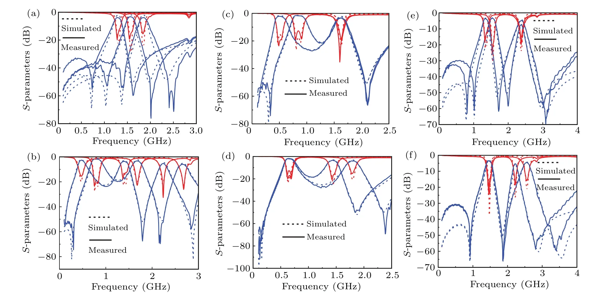
Fig.9. Simulated and measured results for(a)D1: OFF,D2: OFF,single-channel;(b)D1: ON,D2: ON,triple-channel;(c)D1: ON,D2: OFF,dual-channel,channel 1 tunable;(d)D1: ON,D2: OFF,dual-channel,channel 2 tunable;(e)D1: OFF,D2:ON,dual-channel,channel 2 tunable;and(f)D1: OFF,D2:ON,dual-channel,channel 3 tunable.

Table 3. Comparison between our filter and reported reconfigurable filters.
4. Conclusions
The switchable and tunable triple-channel bandpass filter proposed in this paper realizes the free switching among single-channel, dual-channel, and triple-channel by loading varactors and switching diodes on the resonator, and each channel is independently adjustable. In addition, a rigorous rank criterion is proposed.
Acknowledgements
Project supported by the National Natural Science Foundation of China (Grant No. 61471094) and the Science and Technology Support Program of Sichuan Province, China(Grant Nos.2019YFG0499 and 2020YFG0231).

- Chinese Physics B的其它文章
- Real non-Hermitian energy spectra without any symmetry
- Propagation and modulational instability of Rossby waves in stratified fluids
- Effect of observation time on source identification of diffusion in complex networks
- Topological phase transition in cavity optomechanical system with periodical modulation
- Practical security analysis of continuous-variable quantum key distribution with an unbalanced heterodyne detector
- Photon blockade in a cavity–atom optomechanical system