
Study of a 105 GHz short-pulse dummy load for the electron cyclotron resonance heating system with the quasi-optical method
2022-09-06 13:04ShouqiXIONG熊寿齐DonghuiXIA夏冬辉MeiHUANG黄梅GangyuCHEN陈罡宇WentingWENG翁文婷GuoyaoFAN范国垚andYuanPAN潘垣
Plasma Science and Technology 2022年10期
关键词:黄梅
Shouqi XIONG (熊寿齐),Donghui XIA (夏冬辉),Mei HUANG (黄梅),Gangyu CHEN (陈罡宇),Wenting WENG (翁文婷),Guoyao FAN (范国垚) and Yuan PAN (潘垣)
1 International Joint Research Laboratory of Magnetic Confinement Fusion and Plasma Physics,State Key Laboratory of Advanced Electromagnetic Engineering and Technology,School of Electrical and Electronic Engineering,Huazhong University of Science and Technology,Wuhan 430074,People’s Republic of China
2 Southwestern Institute of Physics,Chengdu 610041,People’s Republic of China
Abstract The accurate power measurement is important for an ECRH system in tokamak.The dummy load is designed and developed for the measurement of the millimeter wave power.This work analyzes the dummy load based on the quasi-optical method and the ray tracing method.The reflectivity and thermal deposition of the dummy load have been considered to ensure the safety of the entire system.High-power tests have been carried out at a 105 GHz/500 kW ECRH system.The results of the tests indicate that the designed dummy load is stable and valid.
Keywords: dummy load,power measurement,quasi-optical method,ray tracing,ECRH
1.Introduction
The high power gyrotron testing is one of the necessary steps in the development of millimeter wave systems for fusion research [1].Dummy loads are used to absorb the power generated by gyrotrons,and it is used to test the performance of high-power gyrotrons and measure the microwave power of high-power short-pulses.
For the continuous wave (CW) dummy load,the continuous heating of the incident wave power may cause cooling water to boil.Therefore,the CW dummy load needs greater heat dissipation capacity.The flow rate of the CW dummy load is higher.The heat capacity of the dummy load is also larger.Compared to the CW dummy load,short-pulse dummy loads are usually designed to be smaller with a lower water flow rate.
Most of the dummy loads consist of a shell,an aperture on the one side of the dummy load and a mirror opposite the aperture.There are two kinds of common dummy loads in the worldwide,namely spherical dummy loads and cylindrical dummy loads [2,3],and the section views of the above two dummy loads are shown in figure 1.
The concept of integrating sphere is the starting point for the first designing matched dummy load.A spherical dummy load can be used to measure the microwave power for Gaussian beam or HE11mode [2,4,5].The inner surface of the spherical dummy load is plated with a high reflectivity coating to absorb the incident wave power,and the microwave is reflected in the spherical dummy load back and forth.The coating of the dummy load will be peeled from the shell if thermal fatigue appears.The mirror is used to spread the incident wave power and reduce the energy density of the wave power.
Another kind of dummy load is the cylindrical dummy load [6-8].The length of this kind of dummy load is bigger than the spherical dummy load.The inner surface of the dummy load is encircled by cooling pipes.Cooling pipes are fabricated by metal material or wave-transparent material.The inner surface of the dummy load can be coated or directly covered by the cooling pipe.The effect of the mirror is similar to the mirror of the spherical dummy load.
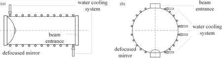
Figure 1.Section view of the cylindrical dummy load (a) and spherical dummy load (b).
There is an aperture as the entrance of the incident wave for both the sphere dummy load and the cylindrical dummy load [2-4,6].The incident wave power is always wanted to be fully absorbed.However,some of the incident wave power cannot be absorbed by the dummy load and will escape from the entrance.Those rays will not heat the cooling water.This phenomenon will influence the accuracy of the measurement results.Because the dummy load calculates the power of the incident wave by measuring the temperature change of the cooling water.Moreover,this part of the rays will damage the wave source and threaten the security of the entire system when the reflected wave power returns to the gyrotron along the transmission line.Although the mirror can help to reduce the reflectivity of the dummy load,damage caused by the reflected wave power can still exceed the affordability of the ECRH system.
The reflectivity of the dummy load is difficult to be measured in experiments because the reflected wave power coexists with the incident wave power,and the energy of the reflected wave is quite lower than the incident wave power.Generally,it is necessary to construct a model to analyze the reflectivity of dummy loads.Considering that the size of the dummy load can reach a few meters,which is much longer than the wavelength,a quasi-optical model has been constructed.In this quasi-optical model,the incident wave is considered as a Gaussian beam [4,9].The analytical process of the dummy load is based on the quasi-optical formulas introduced in section 2.We have also constructed a ray tracing model of the dummy load to verify the accuracy of the quasi-optical model.The dummy load matched for J-TEXT ECRH system has been analyzed by these two methods.The analytical results and corresponding tests have proved the security and the reliability of the dummy load.
This work investigated the analyzing process of the dummy load and focused on the reflectivity and power density of a dummy load.Section 2 introduces the principle and analytical method of the cylindrical dummy load.Section 3 introduces the calculation result of the dummy load matched for J-TEXT ECRH system.Section 4 analyzes the effect of the mirror.Some related high-power tests are introduced in section 5.Finally,a summary has been given in section 6.
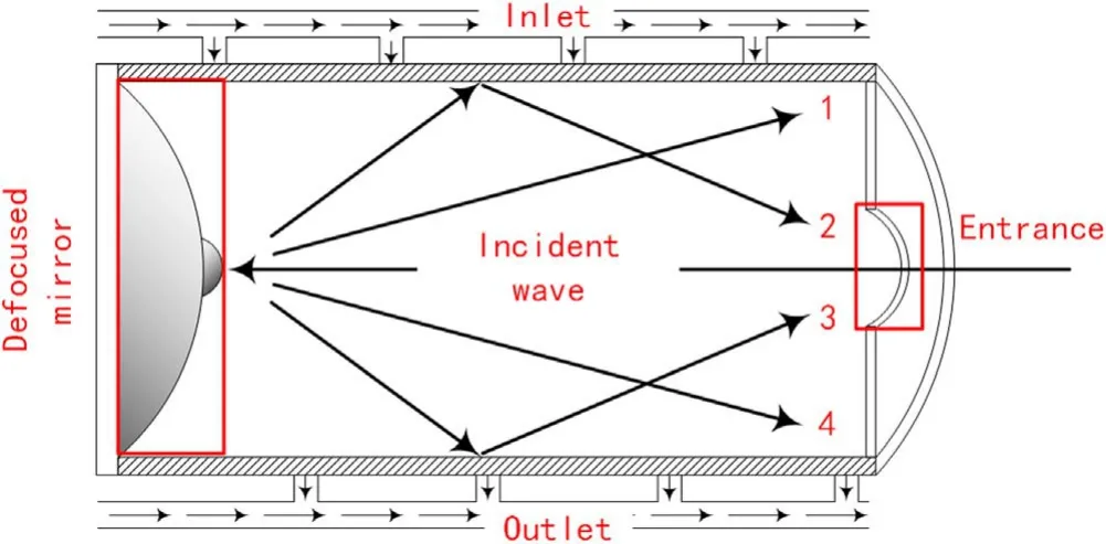
Figure 2.The structure of the cylindrical dummy load and the propagation process of the microwave power in the dummy load.
2.Analytical method of cylindrical dummy loads
2.1.Basic structure of the cylindrical dummy load
The structure of the cylindrical dummy load and the propagation process of the microwave is shown in figure 2.The energy of the incident wave is concentrated in the central area as HE11mode is the propagation mode of microwaves [2].The energy density of the incident wave power is too high,and it cannot be absorbed by the dummy load directly.Therefore,a mirror is designed to reduce the energy density of the incident wave power.The divergence of the reflected wave will increase,and the energy density will decrease after the mirror acts on the incident wave power.Those reflected waves will be dispersed to two kinds of rays.Most rays(ray 1 and ray 4 in figure 2) are absorbed by the dummy load after repeated reflection occurred at the inner surface.A small fraction of rays(ray 2 and ray 3 in figure 2)will return to the waveguide from the entrance [10].The energy of the absorbed rays will be converted to thermal energy,warming the cooling water.
2.2.Quasi-optical method
The dummy load containing a double spherical reflector can be analyzed with quasi-optical formulas as the incident beam of the dummy load is the Gaussian beam.The study of the propagation mechanism of the Gaussian beam is the first step of the quasi-optical method.
When a spherical mirror acts on the incident Gaussian beam,the parameters of the reflected Gaussian beam can be calculated by a series of quasi-Gaussian formulas.The relationship between the incident wave parameters and the reflected wave parameters is shown in formula 3,where z0,ω(zr0)and zr0,ωr(zr0)are the waist position and waist radius of the incident Gaussian beam and reflected Gaussian beam respectively
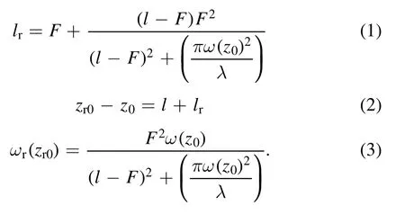
Here,l is the distance between the beam entrance to the diverging mirror of dummy loads.lris the distance between the waist of the reflected Gaussian beam to the diverging mirror of dummy loads.The focal length F of the diverging mirror could be simplified as F = −R/2,where R is the radius of diverging mirror.
The energy density of the Gaussian beam can be calculated by the parameters spot radius ω(z)[11].Spot radius ω(z)can be determined by the wavelength λ and the beam waist radius ω(z0).
When the reflection coefficient T of the inner surface of the dummy load remains at a relatively low level,and it is a fixed value,we can derive the following equations from formulas (1)-(3):
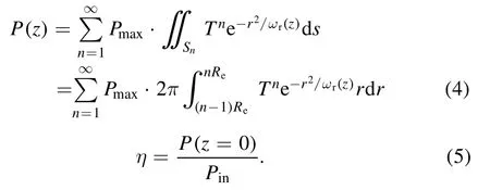
Here,Reis the cavity radius,and η is the reflectivity of the dummy load.Pmaxis the maximum value of the energy flow of the reflected Gaussian beams,and sign n is the number of times that the rays are reflected in the cavity of the dummy load.
For the dummy load that the mirror consists of two spherical mirrors,we can split it into two individual dummy loads,and each dummy load has only one spherical mirror.The section views of two individual dummy loads are shown in figure 3.
The incident microwave power of the dummy load can be derived into two parts.One part is reflected by the main body of the mirror,and the other is reflected by the small spherical mirror.The reflected wave of each individual system is Gaussian beam,and it can be can be calculated by the formulas (4).
The defocused mirror in figure 3(a) with a bigger radius is used to diverge the incident wave power.Furthermore,the defocused mirror in figure 3(b)with a smaller radius is used to reduce the reflectivity of the dummy load.
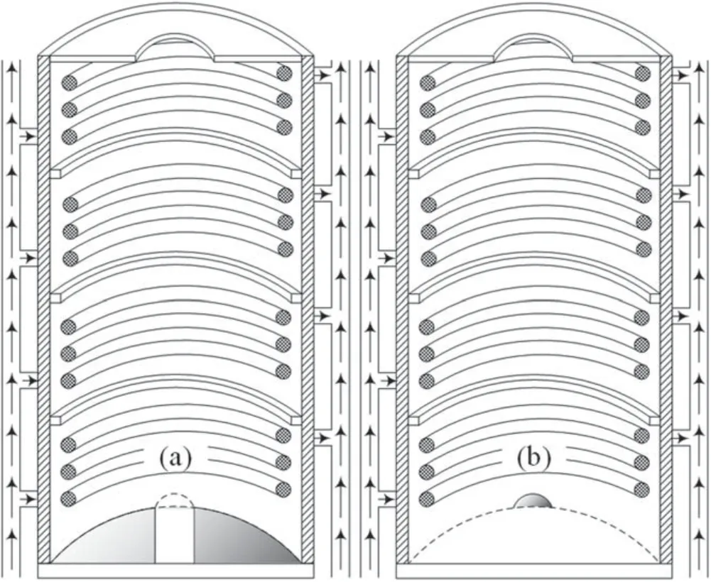
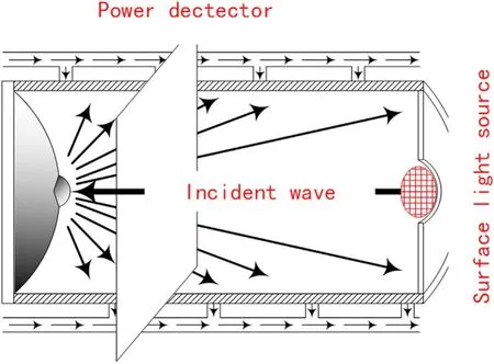
Figure 4.Schematic diagram of the ray tracing simulation of the dummy load.
The energy flow of these two parts is respectively denoted as P1(z) and P2(z).The energy flow P(z) of the dummy load is equal to the sum of P1(z) and P2(z).
2.3.Ray tracing simulation
We can also use ray tracing simulation to analyze the reflectivity and other parameters of the dummy load.When the ray tracing simulation is performed,the incident wave power of the dummy load is set as a surface light source which emits numerous of rays (as shown in figure 4).The power of each ray is distributed by the software automatically according to Gaussian distribution.The inner surface of the dummy load is simplified to be flat during the simulation.
All the rays will reflect back-and-forth in the dummy load.The trajectory of each ray is calculated independently and will be detected by a detector we set up.The detector will record the numbers,the energy and the position of the rays passing through.Then the data can be used to analyze the power density distribution of arbitrary cross section and the reflectivity of the dummy load.
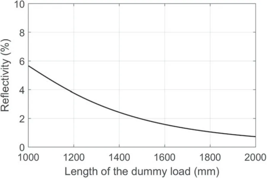
Figure 5.Relationship between the length of the dummy load and the reflectivity calculated by quasi-optical method.
Ray tracing method has been used in the analytical process of the dummy loads for the ECRH system on W7-X[9],FTU[12],etc.By comparing the analytical results of the quasi-optical method and the results of ray tracing method,we can confirm the accuracy and applicability of the quasioptical method.
3.Analytical results of the dummy load
J-TEXT tokamak has been equipped with an ECRH system and a well-matched dummy load.The dummy load can deal with 500 kW/1 s incident wave power generated by the gyrotron.The diameter of the dummy load is decided by the spot radius of the incident wave power.The spot radius of the incident wave at the position of the mirror is around 65 mm.A dummy load with a diameter twice the spot of Gaussian beam (about 250 mm for the dummy load of the J-TEXT ECRH system) is appropriate.The flow rate of the dummy load for 500 kW for 1 s duration is about 0.7 l s−1,and the maximum temperature rise is about 10°C-20 °C.
We have also researched the influence of the length on the reflectivity.A dummy load with a length of 1500 mm is designed from the curve in figure 5.The reflectivity of the dummy load is about 2%,which is a low level for an ECRH system.
3.1.The reflection coefficient of the cooling pipe
The dummy load absorbs microwave power through the cooling water pipes laid on the inner wall of the cylindrical shell.For different materials,their ability to absorb microwave power differs from each other.Cooling pipes made of low reflection coefficient T material can absorb microwaves better.The reflection coefficient T of the dielectric material can be calculated by the Fresnel formula.The electric field vector of the incident wave is decomposed into two components: the components perpendicular to the incident plane respectively (S-component) and the components parallel to the incident plane (P-component).
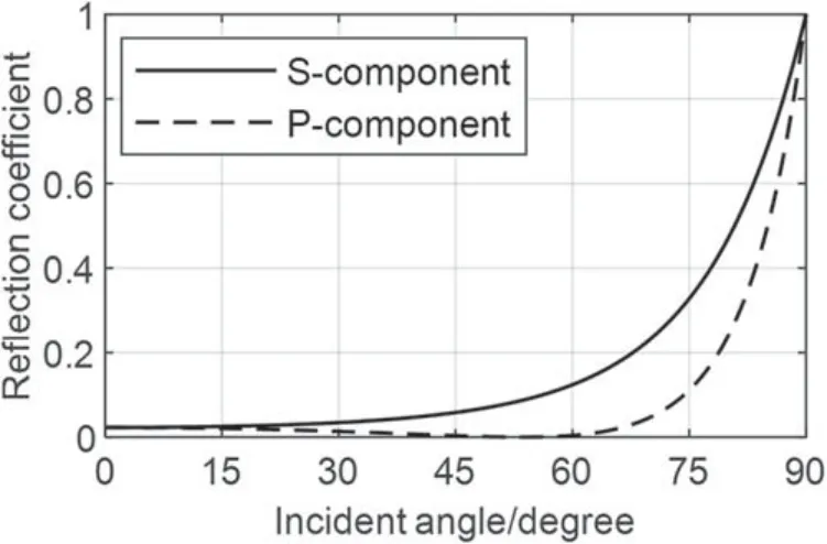
Figure 6.Reflection coefficient T of the material Polytetrafluoroethylene(PTFE),the ratio of the S-component and P-component is determined by the polarization direction of the microwave.

Table 1.Physics properties of PETE.
The reflection coefficient T is shown in figure 6 and the physical properties of PETE are shown in table 1.The reflection coefficient T of PTFE is quite low.While the cooling pipes act on the reflected wave power,most of the microwave power is absorbed by cooling water.For this reason,PTFE is selected to be used as the material of the cooling pipe.
Fresnel formula indicates that reflection coefficient T is not a constant,and it varies with the incident angle.However,it is not easy to get the exact values of the incidence angle of each ray.An alternative method is to replace the varying reflection coefficient T(θ) with a fixed equivalent reflection coefficient Tr.The equivalent reflection coefficient Trcan be regarded as the average of the reflection coefficients of all the rays.It depends on the ratio of each polarization component and the incident angle distribution of all the rays.As shown in figure 6,the reflection coefficient of PTFE is smaller than 0.2 when the incident angle is smaller than 60° (the incident angles of the most of rays in the dummy load are smaller than 60° for the dummy load of J-TEXT ECRH system).Therefore,the equivalent reflection coefficient Trin the dummy load is selected as an approximation (for PTFE reflection coefficient Tris about 0.1-0.2).We select several different reflection coefficients Trto confirm that the dummy load has enough low reflectivity and is reliable.
3.2.The reflection coefficient of the cooling pipe
The energy flow density in the cross section of the dummy load at z=300 mm is shown in figure 7.The left one was calculated by the quasi-optical method,and the right one was calculated by ray tracing.The two images in figure 7 are very close to each other.As shown in figure 7,the energy density at the center of the images is much lower compared with the surrounding energy density,which can help to reduce the reflectivity of the dummy load.
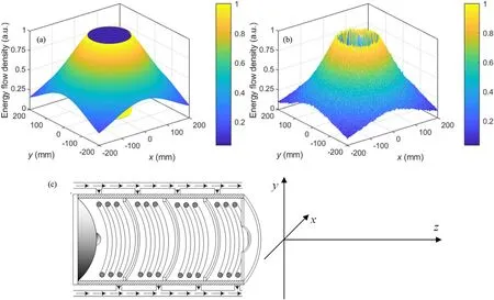
Figure 7.(a)The energy flow density calculated by quasi-optical formulas(z=300 mm).(b)The energy flow density analyzed by ray tracing simulation at the same position.(c) The coordinate diagram of the dummy load.
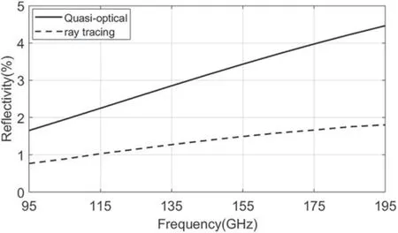
Figure 8.Frequency characteristics of the dummy load.
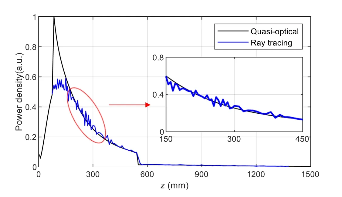
Figure 9.Power density distribution along the z-axis,f=105 GHz.Blue curve:simulation result calculated by ray tracing.Black curve:result calculated by the quasi-optical method.
The frequency response of the dummy load is shown in figure 8.A positive linear relationship between reflectivity and frequency is observed.The collimation of the beam increases as the frequency increases.Meanwhile,there will be higher reflected wave power returning to waveguides from the entrance,which could cause the reflectivity of the dummy load to increase.We can also observe that the reflectivity of the dummy load changes slowly while frequency changes from figure 8.This means the frequency band of dummy load could be quite wide typically.
When the frequency of the incident wave is 105 GHz,the reflectivity of the dummy load is about 1%-2%.The result shows that the reflected wave power will cause little damage to the waveguide and gyrotron because the energy of the reflected wave power is quite low.
Another factor concerned a lot is the power density distribution of the dummy load [11,13-15].To avoid the appearance of thermal fatigue cracks,the power density distribution of the dummy load is always required to be uniform.
The results of power density distribution are shown in figure 9.There are some differences between the curves of the quasi-optical model and the ray tracing model,especially in the section of z=0-150 mm.On the contrary,the two curves are closer in the section z=150-1500 mm (as shown on the right of figure 9).
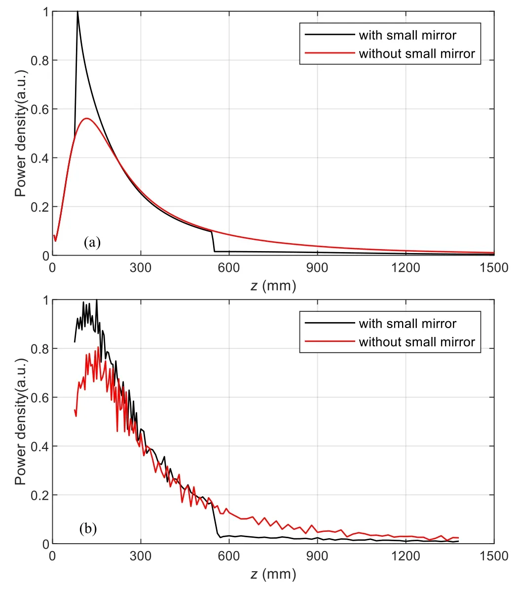
Figure 10.(a) Power density distribution of the dummy load calculated by the quasi-optical method.The reflectivity of the dummy load is 1.96% (with the small mirror) and 4.59% (without the small mirror),respectively.(b) Power density distribution of the dummy load in ray tracing.The reflectivity of the dummy load is 0.90% and 4.78%,respectively.
In figure 9,the maximum value of the energy density distribution calculated by the quasi-optical method (black curve) is much higher than the blue curve.There might have been two main reasons.One reason is that far-field approximation and paraxial approximation have been used in the quasi-optical method.Another reason is the use of the equivalent focal length F = −R/2 when we use the quasioptical method.Those two reasons bring much deviation to the two kinds of analytical methods,especially when the coordinate z is small.
The maximum power density of the dummy load is 0.094 kW cm−2(raytracing method)/0.178 kW cm−2(quasioptical method)for a 500 kW short-pulse test.Referring to the previous research,the maximum power density of the dummy load is within a safe range [12,15].The analytical result proves that the dummy load of the J-TEXT ECRH system can afford the megawatt-level short-pulse test.
4.Discussion of the dummy load
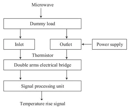
Figure 11.Schematic diagram of the temperature measurement system.
As we have mentioned in section 2,the mirror of the dummy load contains a small spherical mirror to reduce the reflectivity.Microwave power reflected by the small spherical mirror is more likely to be absorbed by the dummy load rather than escape from the entrance.However,the small spherical mirror could also cause an increase of the maximum power density,which is always required to be avoided(as shown in figure 10).
Using equivalent focal length F = −R/2 will also bring deviation to the analytical result of the reflectivity.For the cylindrical dummy load with the small mirror (which has a small radius),the analytical result of the quasi-optical method(1.96%)is quite different from the analytical result of the ray tracing (0.90%).For the cylindrical dummy load without the small mirror(the main body of the mirror has a bigger radius),the values (4.59% and 4.78%) of the reflectivity of the two methods are quite close.
The dummy load with a small mirror has a worse uniformity and a lower reflectivity.Therefore,the size of the small spherical mirror needs to be selected carefully.If the radius of the small spherical mirror is too big,it will cause a more serious problem with the uniformity of power distribution.If the radius of the small spherical mirror is too small,the reflectivity of the dummy load can reach a high level and will threaten the entire system.
5.High power test of the dummy load
Utilizing the 105 GHz ECRH system on J-TEXT tokamak,high-power tests of the dummy load have been carried out.The gyrotron generates high-power millimeter wave power,guided by the transmission line and finally injected into the dummy load.The thermal energy deposited in the load is absorbed by cooling water,so we can calculate the millimeter wave power by measuring the temperature rise of the cooling water.The calorimetric measurement schematic diagram is shown in figure 11,and the high-power test platform is shown in figure 12.
A power supply is used as a controlled heat source to simplify the calculation process.The ratio of the temperature signal integration to the input wave power is denoted as Cload.Furthermore,the ratio Cloadcan be measured by an individual test with the known power supply.Then the ratio Cloadcan be applied to the high-power test and help to calculate the exact power of the incident wave [2,16].The ratio Cloadwill be influenced by the environmental factors such as temperature and flow rate [2].
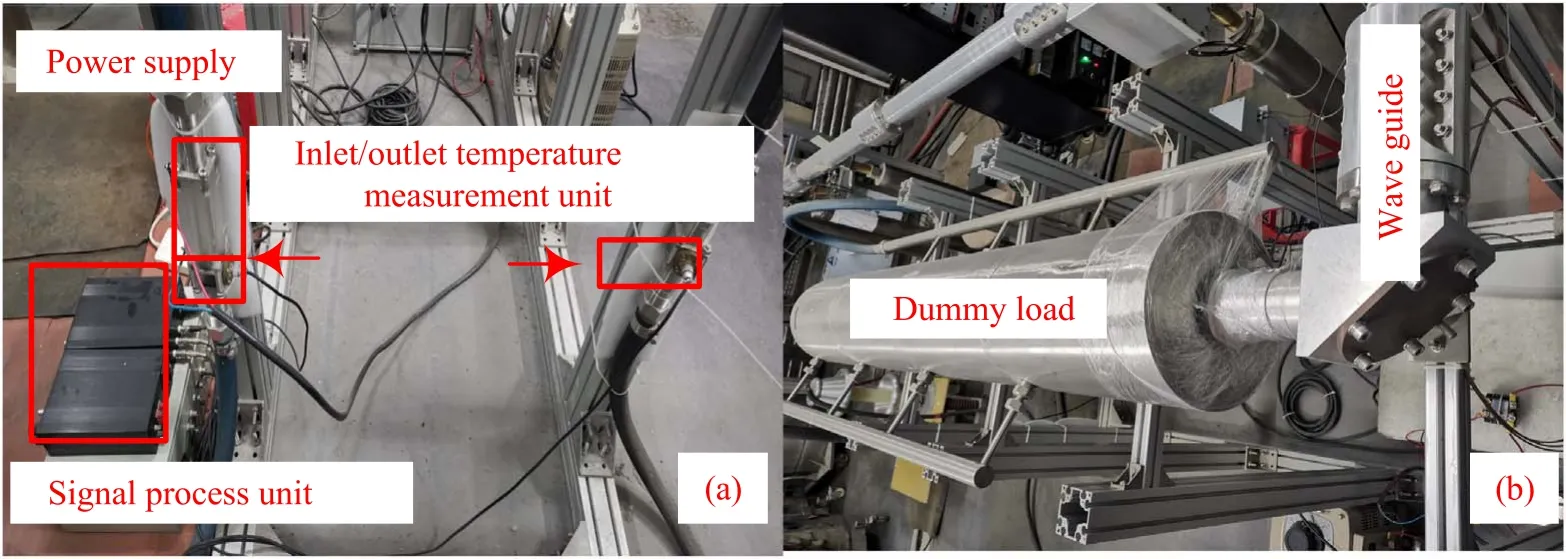
Figure 12.High-power test platform of J-TEXT ECRH system.
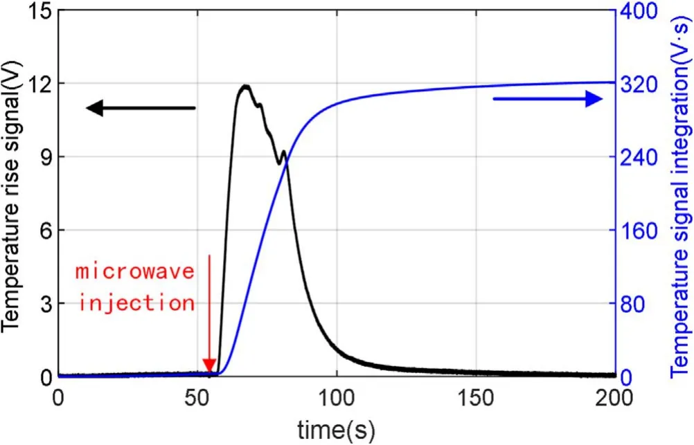
Figure 13.Temperature rise diagram of the cooling water.Pulse width of the incident wave power is t = 500 ms.The water flow rate of the dummy load is around 0.7 l s−1.The absorbed energy of the dummy load is approximately equal to the energy of the incident wave.
The high-power tests have been carried out on the platform of the J-TEXT ECRH system.The result of one experiment is shown in figure 13.The temperature signal integration of the test is 321 V·s,Cloadequals 2.6 J/(V·s),and the calculated millimeter wave power is 417 kW/0.5 s.During the equipment acceptance test,the gyrotron is operated under the same parameters,and the measured power is 400 kW.The difference between the two measured results is about 5%.The repeated tests of the same power and pulse widths have verified the stability and reliability of the results.
Until now,more than 1200 experimental shots have been successfully carried out,and the dummy load keeps safe and stable all the time.
6.Conclusion
We researched the propagation mechanism of the Gaussian beam in cylindrical dummy loads and developed a quasioptical method.A corresponding quasi-optical model has been constructed to analyze the dummy loads characteristics used for high-power gyrotrons.Ray tracing has been used to verify the results of this quasi-optical model.
The two analytical methods have been applied to the dummy load of the 105 GHz ECRH system for J-TEXT tokamak.Characteristics of the dummy load have been researched,especially the reflectivity and the power density.Results show that the reflectivity is less than 2.5% under routine operation,and the power density distribution is within allowable limits.The analytical results were further compared,and we concluded some useful advice for the design of the dummy load’s structure.
Finally,high power tests have been implemented on the 105 GHz dummy load to testify its stability and reliability.
Acknowledgments
The authors would like to thank the ECRH group with valuable discussions about the dummy load,the wave heating groups of the auxiliary heating department at SWIP as well as other members of the J-TEXT laboratory for their assistance.This work is supported by the National Key Research and Development Program of China(Nos.2017YFE0300200 and 2017YFE0300204) and part by National Natural Science Foundation of China (No.51821005).
猜你喜欢
上海文学(2022年7期)2022-07-09
健康体检与管理(2022年4期)2022-05-13
黄梅戏艺术(2022年1期)2022-05-07
黄梅戏艺术(2021年2期)2021-08-19
——丁俊美
黄梅戏艺术(2021年4期)2021-02-25
理科考试研究·高中(2017年7期)2017-11-04
美与时代·美术学刊(2016年7期)2016-05-14
妇女(2015年10期)2015-10-13
小小说月刊(2015年9期)2015-05-14
传奇故事(破茧成蝶)(2015年8期)2015-02-28
 Plasma Science and Technology2022年10期
- Plasma Science and Technology的其它文章
- Cross-focusing of two chirped Gaussian laser beams and THz wave generation in plasmas of multi-ion species under a weakly relativistic and ponderomotive regime
- Simulations of energetic alpha particle loss in the presence of toroidal field ripple in the CFETR tokamak
- Impact of core electron temperature on current profile broadening with radiofrequency wave heating and current drive in EAST
- Study on divertor heat flux under n=3 and n=4 resonant magnetic perturbations using infrared thermography diagnostic in EAST
- CBETor:a hybrid-kinetic particle-in-cell code for cross-beam energy transfer simulation
- Ionization process and distinctive characteristic of atmospheric pressure cold plasma jet driven resonantly by microwave pulses